 FREE 1 to 3-Day Delivery on Orders $149+ Details
How to Install Steeda Chromoly Steel Lower Control Arms on Your 2005-2012 Mustang
Installation Time
2 hours
Tools Required
- (2) Wheels Chocks (Not necessary if using a lift)
- Jack (Not necessary if using a lift)
- Jack Stands (Not necessary if using a lift)
- 18mm Socket (1/2")
- 1/2" Ratchet (longer is better)
- 1/2" Torque Wrench (must be capable of torqueing to 129 ft/lbs.)
- Dead Blow Hammer (non-marking type)
- Can Penetrating Oil
- Tire iron
- Several pair of rubber gloves for applying grease - it’s super sticky and hard to clean off
Installation
NOTE: The following installation was performed on a 2007 Mustang GT/California Special. The control arms were previously sold in a blue color, but now they are sold from Steeda in a powdercoated silver color.
Parts Included in Box:
- (2) Lower Control Arms
- (2) Washers – Steel
- (2) Tubes Grease
- (2) Wire Ties
- Instruction Sheet (Steeda)
Parts Recommended:
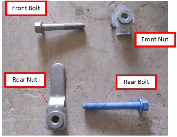
- (2) Ford Front Bolts (Rear Lower Control Arm) - Ford Part# W711504-S439
- (2) Ford Front Nuts (Rear Lower Control Arm) - Ford Part# W710089-S440
- (2) Ford Rear Bolts (Rear Lower Control Arm) - Ford Part# W704888-S900
- (2) Ford Rear Nuts (Rear Lower Control Arm) - Ford Part# W704991-S900
*Ford recommends replacing the bolts and nuts when changing lower control arms.
Installation Instructions:
1. Place wheel chocks in front of the front tires in order to secure the vehicle from movement during installation. Break loose rear wheel lugs – do not remove.
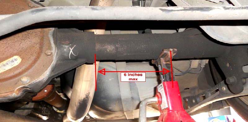
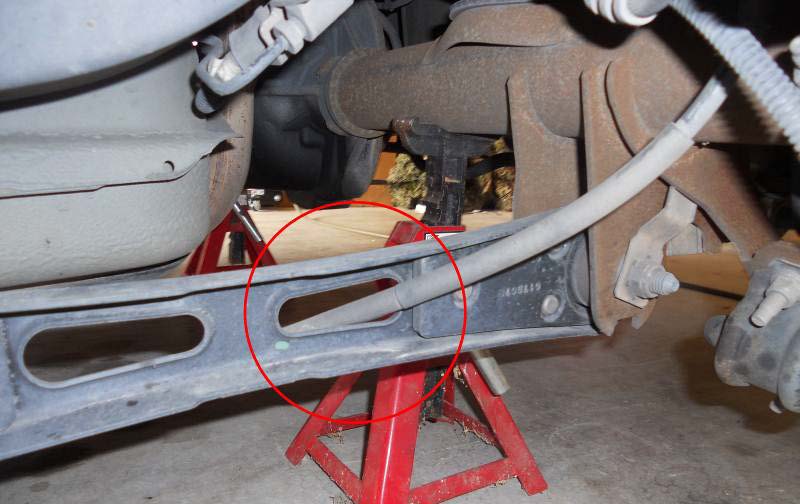
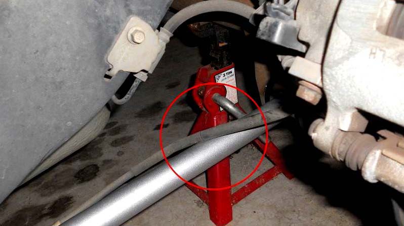
2. Place jack under rear end and jack up vehicle high enough for the axle to rest on jack stands and rear wheels off of the ground. The rear end suspensions must be loaded. Place the jack stands on either side of the rear end supporting the axle. Place the stands an equal distance from where the rear end meets the axle tube. Equal spacing will provide equal loading of the axle and make it easier to line up the bolt holes on the new arms. Do not place the stands more than about 6” on center from the lip where the axle tube meets the rear end (see Figure 1) or else you won’t be able to slide the rear bolt out of the arms. Lower the vehicle onto the jack stands and check for stability and safety. (Never work on a vehicle that is only supported by a jack, always use jacks stands).
3. Remove the rear wheels from the vehicle and place in a secure area. Disengage the parking brake inside the vehicle.
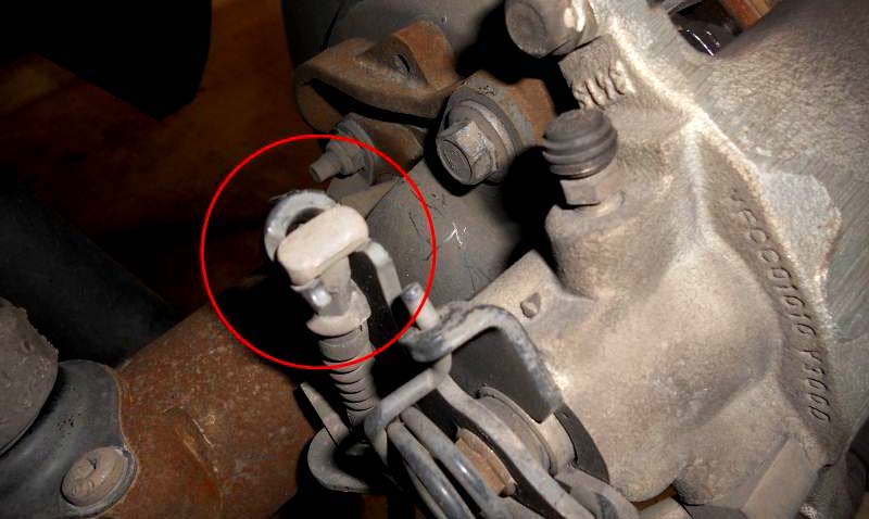
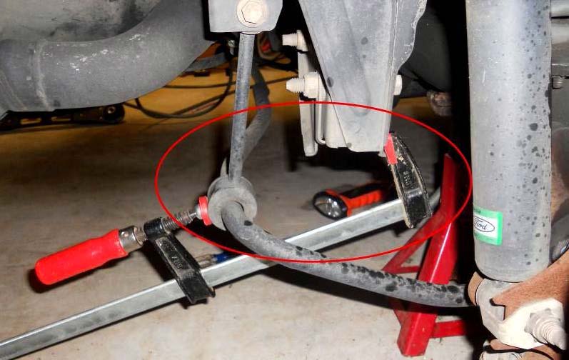
4. Locate the parking brake cable behind the rotor (See Figure 2). Remove the metal clip from the parking brake cable and slide cable from slot (save clip for later).
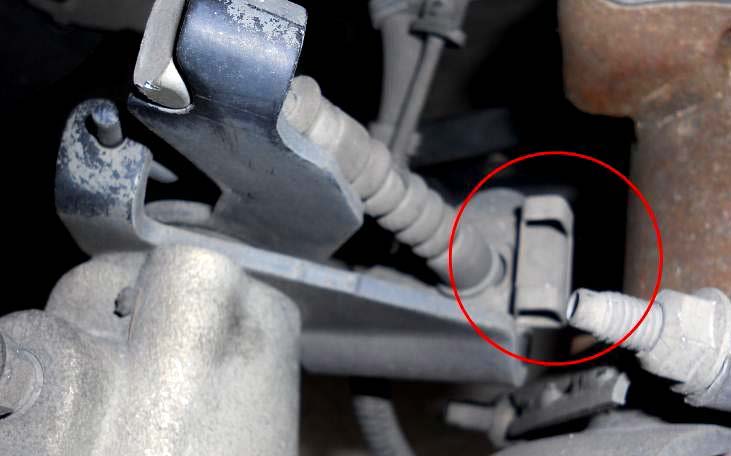
5. Remove cable end from parking cable arm by lifting cable end and twisting out of slot (See Figure 3).
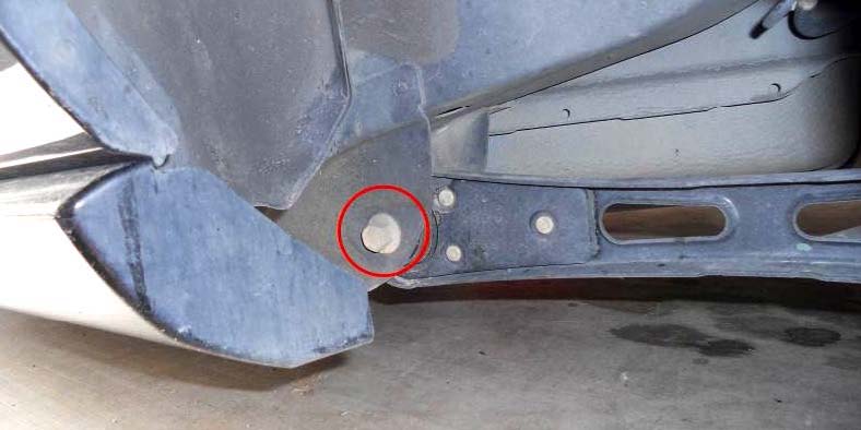
6. Pull the cable through the lower control arm (See Figure 4).
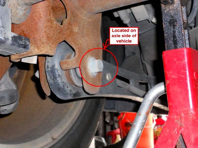
7. Remove the front (Figure 5) and rear (Figure 6) bolts for one of the control arms. Apply Penetrating oil to nuts to assist with removal. Do NOT remove both arms at the same time, the arms provide a horizontal fixed point for the rear axle and can cause the axle to shift and make it more difficult to install the new lower control arms.
8. Remove the old control arm and maintain the proper front to rear orientation. Insert old nuts and bolts into old control arm as they were removed front to front etc. Set this assembly aside and maintain the front to the front in case you need it as a reference for where the bolts and nuts were originally.
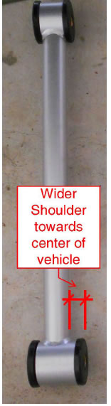
9. Set a new control arm alongside the car. The wide bushing goes in the rear. The rear bushing assembly is not symmetrical: one shoulder is wider than the other one. The wider shoulder points toward the center of the vehicle (See Figure 7). If you’re concerned about getting this wrong, then measure with a tape measure and place a rubber band around the wider side to go toward the center of the vehicle (cut rubber band off later).
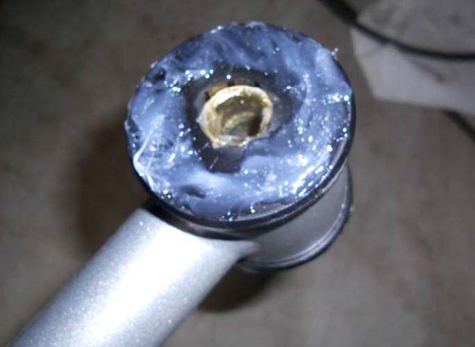
10. Apply one entire tube of provided grease in equal parts to each of the (4) sides of the bushings and spread for an even coat; this will help prevent squeaking (See Figure 8).
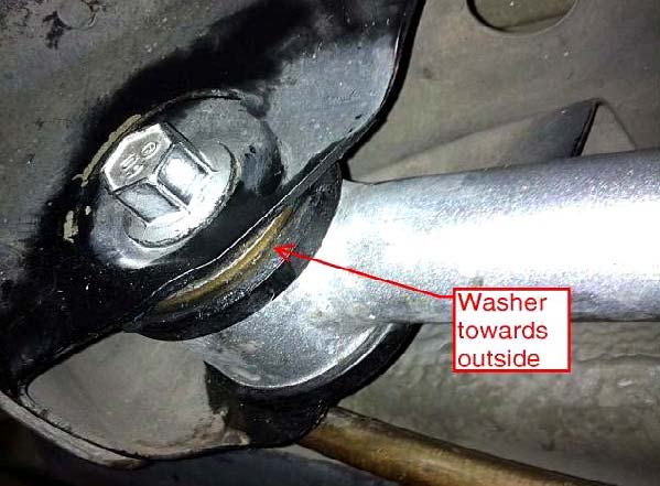
11. Now, rubber gloves will come in handy, as this grease is extremely sticky. Paper towels are also helpful after installation. Install (1) of the provided washers on the control arm, placing it to the outside of the control arm bushing (See Figure 9).
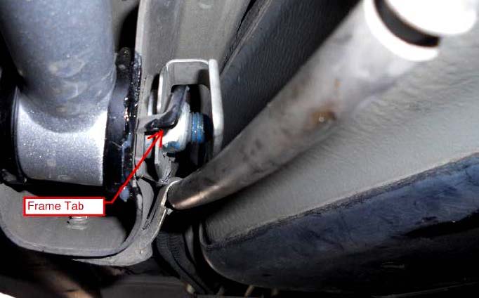
12. Double check orientation and install front of arm into bracket with a new bolt and new nut. Place the nut into the tab on the frame to prevent it from spinning (See Figure 9A). Tighten until threads begin engaging the nut, using the 18mm socket wrench.
13. Slide rear arm bushing into axle bracket. This was a tight fit for my installation. Use the dead blow hammer to persuade it into place. Be careful not to tap arm above the bolt hole. Install new bolt and new nut and secure (See Figure 10).
14. Tighten bolts to the specified torque of 129 ft/lbs. This can be tough when using jack stands (limited space), but it is very important to reach the full torque specification.
15. Route the parking brake cable from the inside of the control arm, then over to the brake assembly. This will keep the cable away from the wheels (See Figure 11). You can use the wire tie to further secure the cable to the control arm.
16. Re-install the cable end of the parking brake cable onto the brake assembly. Pull the cable down into the slot and re-install the metal clip, securing the parking brake cable. From inside the vehicle, test the parking brake to make sure the cable is activating the brake. Completed assembly (See Figure 12).
17. Repeat the entire process for the opposite side of the vehicle.
18. Re-install wheels, hand tighten lug nuts; remove jack stands and lower vehicle. Next, tighten wheel lugs to factory torque settings. Don’t forget to remove tire chocks from front wheels. Test drive your Mustang. Since the new lower control arms are stiffer and have polyurethane bushings instead of rubber, you may experience a small amount of additional road noise and a stiffer ride.
Troubleshooting:
1. If you have difficulty getting the control arm to line up with the rear bolt hole and the dead blow hammer won’t get it done, use the jack to push it up. You must ease the control arm up with the jack; if you push it up past the bolt hole, it will be difficult to move it back down.
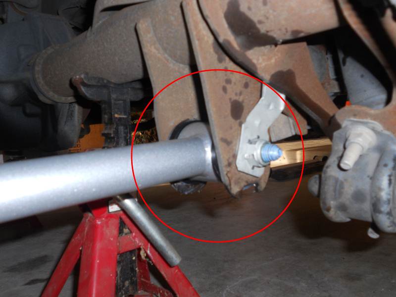
2. When installing the rear bolt, the bolt hole may be lined up vertically, but horizontally it’s off a little bit. One solution is to use a clamp between the rear sway bar and the axle frame bracket to push the axle enough to line up the hole (See Figure 13).
Installation Instructions written by AmericanMuscle customer Emile Newchurch 4.16.12
