FREE 1 to 3-Day Delivery on Orders $149+ Details
How to install Steeda Billet Charge Motion Control Plates on your 2005-2008 Mustang
Installation
Note: Once removed, the Charge Motion Control Plates can not be reinstalled. The Ford Charge Motion Control Plates require precision alignment for proper function.
PREPARING THE CAR FOR THIS PROCEDURE
1. It is important that the engine be at room temperature before beginning this procedure. Fuel may be spilled when removing the fuel line and could lead to a fire. Failure to follow this procedure could result in serious injury and property damage.
2. Disconnect the positive battery terminal from the battery. Using compressed air blow out any dirt or debris that may fall in the engine once the intake manifold is removed.
REMOVING INTAKE MANIFOLD
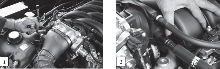
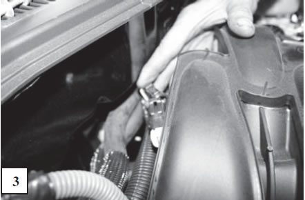
1. Remove vacuum lines from the front of the intake next to the throttle body. The upper vacuum line for the fuel system (with the white clip) should be removed by holding the connector and pulling the hose off. Figure 1 & 2
2. Remove all wiring harnesses connected to the intake manifold by pressing the release and pulling the wire from the connection. There are two connectors on the throttlebody, one on the right side for the fuel injection harnesses and one connection behind the intake manifold, next to the fire wall for the actuator motor.
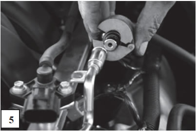
3. Unscrew the clamp and remove the flexable intake-to-filter box intake tube from the throttle body. (flat blade screwdriver or a 8mm socket). Figure 4
4. Remove the wiring harness from the drivers side fuel rail by pressing the red release and pulling the wire away.
5. Next remove the wiring harnesses from all 8 fuel injectors pressing the gray release button and carefully pulling each connector away.
6. Place a shop towel or absorbent cloth beneath the main fuel line connector. Using a spring-lok release tool, disconnect the main fuel line from the drivers side fuel rail. Figure 5
7. Remove the wiring looms from the intake manifold.
8. Remove the four stud bolts that attach the fuel rails. Disconnect the rubber hose above the drivers side fuel rail.
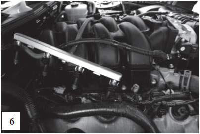
9. When the fuel rail studs are removed, carefully remove the fuel rails with injectors as a unit. (both sides) Figure 6
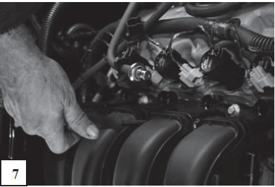
10. Remove the 10 intake manifold bolts. Two bolts are located between the intake runners as shown below. Figure 7
11. Once the bolts are removed, carefully lift the intake manifold from the engine and place on a workbench away from the engine. It is a good practice to cover the intake ports with shop towels until you are ready to reinstall the intake. This will help prevent debris from falling into the engine.
INSTALLING CHARGE MOTION DELETE PLATES
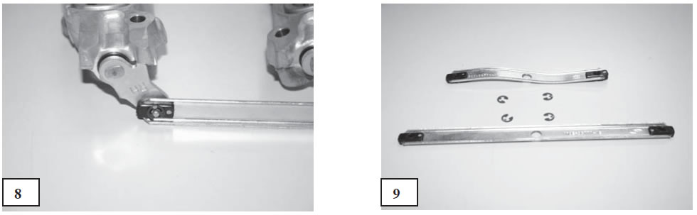
12. Remove the factory Charge Motion Control Plate actuation arms from the actuator drive motor at the rear of the intake manifold by removing the four (4) C-clips. The Actuator should remain attached to the manifold and should be reconnected to the wiring harness unless your computer upgrade has been calibrated for the removal. Figure 8 & 9
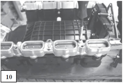
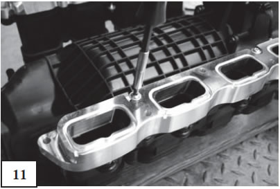
13. Remove the Charge Motion Control Plates, by unscrewing the four (4) Torx screws that attach them to the intake ports (two per side). Figure 10
14. Install the new Charge Motion Delete Plates with the four Torx screws removed in Step 14. Note that there are left and right sides, with the left side marked “LH” and the right side marked “RH”. The gasket groove in the new Steeda Charge Motion Delete Plates should be visible with the spot-face/nitrous ports facing each other. Take care to align the new plates so they fit the O-rings around the intake ports as well as match the injector ports. Figure 11
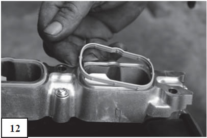
15. Remove the green O-rings from the factory Charge Motion Control Plates and fit them to the new Steeda Charge Motion Delete Plates. Carefully examine the green O-rings prior to installation. Replace them if they are cracked or brittle. Figure 12
16. Re-install the intake by working backwards from Steps 12 thru 2.
17. Once the installation is complete carefully recheck all connections, particularly the fuel line. Start the engine and check the fuel line coupler for leaks. If there is a leak turn the engine off immediately and service the connection.
Note: The addition of a nitrous oxide system requires careful planning and installation. If you are not installing a pre-package kit or you are not an experienced technican with a background in this type of installation, do not attempt it. Have a qualified installer do the work.