FREE 1 to 3-Day Delivery on Orders $149+ Details
How to Install AEM Electronics 96 in. AQ1 OBDII Data Logger Wiring Harness (96-17 All) on your Ford Mustang

Shop Parts in this Guide
STOP! - READ THIS BEFORE INSTALL OR USE!
WARNING:
THIS INSTALLATIONMAY REQUIREWELDING OR INTEGRATION INTO A VEHICLE'S ELECTRICAL SYSTEM. DAMAGE TO SENSITIVEELECTRONICS, FIRE, OR EXPLOSIONMAY OCCUR IF PROPER PRECAUTION IS NOT TAKEN. IF THERE IS ANY DOUBT, DO NOT ATTEMPT THEINSTALLATION AND CONSULT A PROFESSIONAL.
NOTE: IT IS THERESPONSIBILITY OF THEENGINETUNER TO ULTIMATELY CONFIRMTHECALIBRATION USEFOR ANY PARTICULAR ENGINEIS SAFEFOR ITS INTENDED USE. AEMHOLDS NO RESPONSIBILITY FOR ANY ENGINE DAMAGETHAT RESULTS FROMTHEMISUSEOF THIS PRODUCT.
The AEM P/N 30-2907-96 AQ-1 Data Logger Harness has been designed to ensure easy installation, signal integrity, and proper logger operation. The 96" flying leads allow for easy integration into your vehicle for sensor inputs along with preterminated USB, Serial, AEMnet, and OBD-II connectors.
Features
· 96" Flying Leads
· Permanent Power, Switched Power, and Ground
· 4 Analog
· 4 Analog/Frequency
· 3 Digital
· DB9 Serial
· 4 Pin Deutsch AEMnet
· Bulkhead Mount USB w/ dust cap
· 28 Spare Pins
· OBD-II Connector

Overview
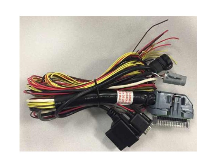
The AEM P/N 30-2907-96 AQ-1 Data Logger Harness has been designed to ensure easy installation, signal integrity, and proper logger operation.
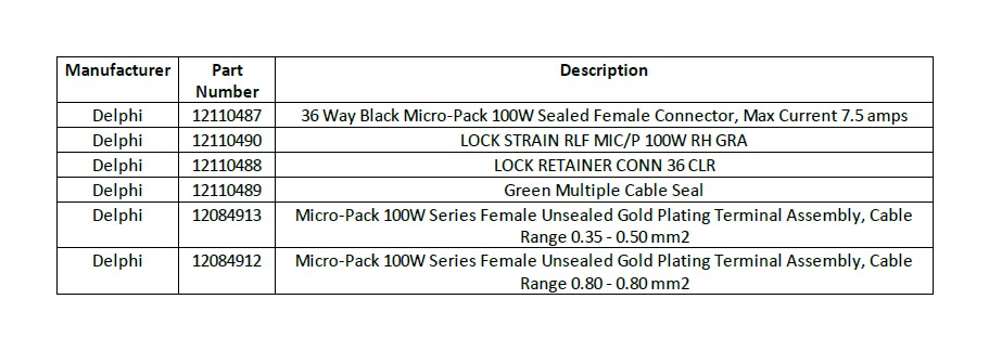
Only skilled, experienced installers should attempt to source and design their own harness. The connector part numbers (AEM does not supply these parts separately outside the 30-2906-96 or 30-2907-96) are provided below for this purpose.
Important Wiring Tips
· Permanent 12V (Pin 6) must be connected to a constant 12V battery source that is not disconnected via a cut-off switch or similar.
· Switched/Ignition 12V (Pin1) must be connected to a switched ignition source that energizes when the vehicle is in use and is off when the vehicle is not in use.
· Frequency inputs (Pins 12-15) must only be connected to clean DC square wave signals. Connections to ignition coils or magnetic/VR sensors will damage the logger.
· CAN wiring (Pins 27-28, 33-34) must utilize twisted pairs with greater than one twist per inch.
· USB wiring (Pins 31-32, 35-36) is only required if users wish to mount a USB port remotely; the integrated USB port functions exactly the same. USB wiring requires special care; please contact the USB consortium (usb.org) for proper wiring conventions.
· Proper crimping, shielding, and harness routing practices should always be implemented.
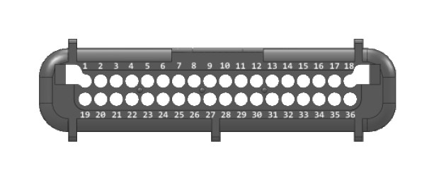
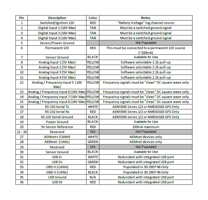
Pinout