FREE 1 to 3-Day Delivery on Orders $149+ Details
How to Install AEM Electronics Water/Methanol Failsafe Device (79-17 All) on your Ford Mustang

Shop Parts in this Guide
WARNING:
Completely read this instruction manual before attempting to install or use this product! This installation is not for the electrically or mechanically challenged! Use this system with EXTREME caution! Misuse of this system can damage your engine!
If you are uncomfortable with anything about this, please refer the installation to an AEM trained tuning shop or call 800-423-0046 for technical assistance. You should also visit the AEM Performance Electronics Forum at http://www.aemelectronics.com.
NOTE: AEM holds no responsibility for any engine damage that results from the misuse of this product!
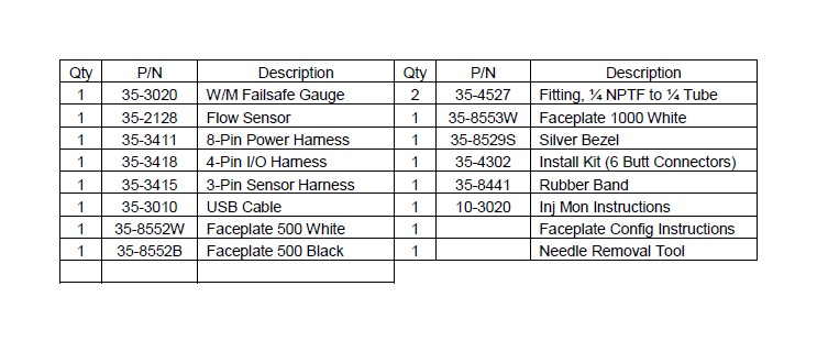
WATER/METHANOL FAILSAFE PARTS LIST
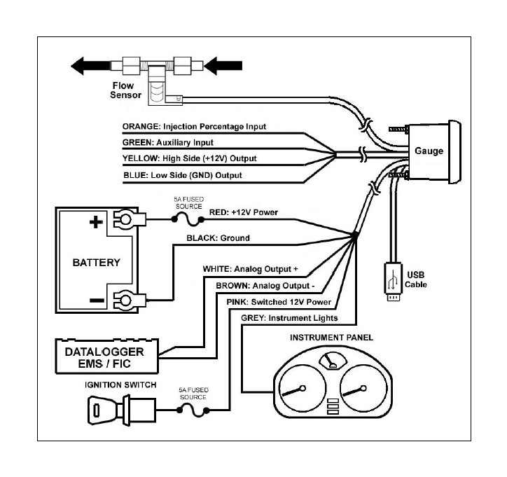
INSTALLATION DIAGRAM
OVERVIEW
Water/methanol injection is used to lower air charge temps and reduce detonation which allows for aggressive tuning to be utilized while using a low octane base fuel. When relying heavily on water/methanol injection a safety device is strongly recommended in order to prevent detonation and possible engine damage in the event of a leak or clog. Progressive injection systems have a dynamic flow output and monitoring both the injection flow rate and the injection percentage means a high level of engine protection can be achieved.
The AEM Water/Methanol Failsafe is an advanced safety device that allows the end user to closely monitor the performance of their water/methanol injection system. Water/Methanol Failsafe collects flow versus injection percentage data points and plots them in a graph to create an injection flow curve using PC configuration software. “Injection percentage” is a calculated value that is indicative of injection pump or injection valve duty cycle and is based on a scale of 0-100 percent.
Once a baseline flow curve is established, the end user can then assign high and low flow threshold lines that can be contoured to closely follow the baseline flow curve. If injection data points occur outside of the high and low flow threshold lines, an alarm condition will be triggered. Injection data points that occur in the area between the high and low flow threshold lines are considered acceptable and an alarm condition will not be triggered.
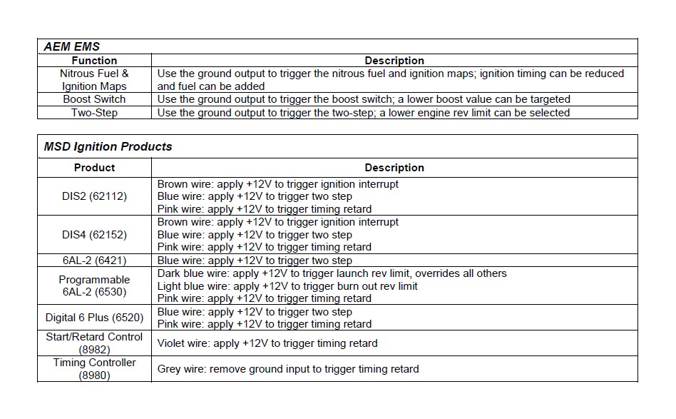
Once an alarm condition is triggered, two outputs will activate along with a visual alarm alert. The Water/Methanol Failsafe has one high side or 12 volt output and one low side or ground output. Both outputs can be configured to turn on or off when an alarm condition is triggered. These outputs can be used to turn off a boost controller, retard ignition timing, switch fuel and timing maps, activate a warning light or buzzer, or deactivate another external system (nitrous, etc.). The gauge backlighting and needle can also be set to flash to notify the vehicle operator of an alarm condition.
The Water/Methanol Failsafe also has an auxiliary input that can be used to trigger an alarm condition. Users with the AEM Water/Methanol Injection System (PN 30-3000 & 30-3001) can use the “Boost Safe” ground output to trigger the auxiliary input if any of the internal fault conditions are detected by the AEM progressive controller.
NOTE: It is HIGHLY recommended that the Water/Methanol Failsafe be used in conjunction with the AEM Water/Methanol Injection Filter (AEM part# 30-3003). Using a filter will maximize the performance and longevity of your flow sensor as well as your entire injection system.
INSTALLATION
1. Disconnect the negative battery cable.
2. Temporarily install gauge without bracket into desired mounting location. Gauge mounts into a 2 1/16” (52MM) hole. The supplied rubber band can be used as a spacer around the gauge if it fits loosely in mounting hole.
3. Splice into injection line and install flow sensor as close as practically possible to final injection point. Flow sensor can be installed before or after check valves or flow control solenoids. A filter is highly recommended and should be installed ahead of the sensor. Ensure arrow on flow sensor points in the direction of flow. Avoid exposing flow sensor to high heat sources (exhaust, turbo, etc.). Route flow sensor cable to gauge mounting location.
4. Install USB cable so the PC end of the cable is easily accessible and route the gauge end of cable to the gauge mounting location. USB cable is meant to be permanently installed to gauge and left in vehicle. Stow PC end of cable in location such as glove box or center console, etc.
5. Install the 4 & 8 pin harnesses and connect wires as described below:
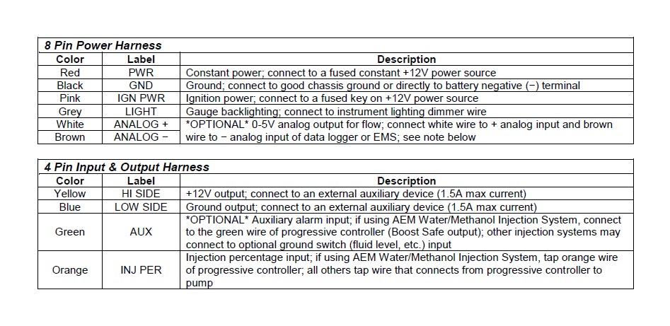
6. NOTE: The analog output is a differential output so the brown wire should be connected to an analog ground input for best results. If the EMS, logger or similar device does not have an analog ground input, the brown wire should be connected to a sensor ground. If no sensor ground is available, the brown wire should be connected to a power ground. The brown wire must be connected in order to obtain correct flow readings from the analog output.
7. Connect all cables and wiring harnesses to gauge. Fully install gauge into hole using mounting bracket and nuts.
PC SOFTWARE
Download and install the Water/Methanol Failsafe configuration software from the AEM Performance Electronics forum at http://forum.aempower.com/forum/. Open the configuration software and connect the USB cable to the PC. If permanent power is present the Water/Methanol Failsafe will turn on with ignition key-on power. Alternatively, the Water/Methanol Failsafe can be bench-programmed outside of the vehicle without powering it by connecting just the USB cable, however, the backlighting, needle and warning lights will not activate.
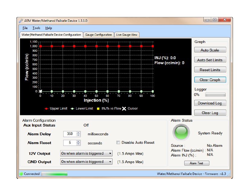
Water/Methanol Failsafe Configuration Tab
This is the section where the flow monitoring and alarm output functionality of the Water/Methanol Failsafe is configured.
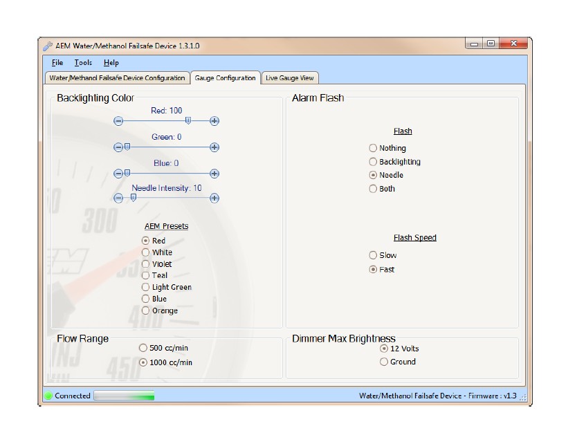
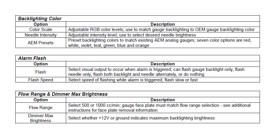
Gauge Configuration Tab
This is the section where the gauge backlighting is configured.
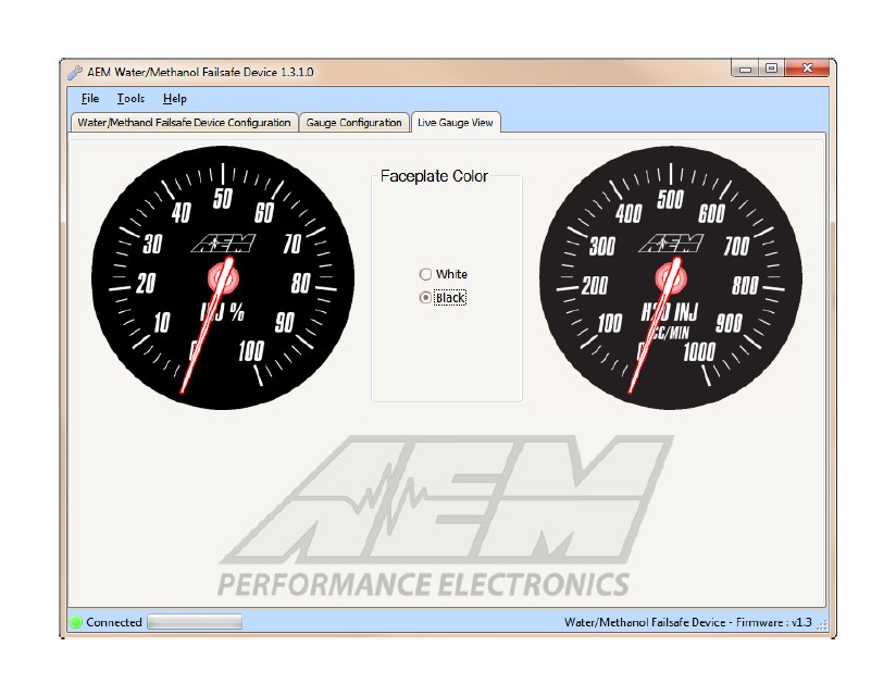
The Water/Methanol Failsafe PC software has a live gauge display. Injection Percentage is shown on the left from 0-100% and flow, in cc/min, is shown on the right. The flow range shown in the live gauge will match the flow range selected in the Gauge Configuration tab. Faceplate color can be black or white.
WATER/METHANOL FAILSAFE CONFIGURATION
The following is a basic guideline strategy for configuring the Water/Methanol Failsafe for the first time. The ideal time to configure the Water/Methanol Failsafe is while the vehicle is being dyno tuned for water/methanol injection. Ensure your injection system is fully functional with no leaks or clogs or other issues before starting to configure the Water/Methanol Failsafe!
1. In the Water/Methanol Failsafe Configuration tab, click on Clear Graph and Reset Limits to zero out all settings.
2. Complete a series of long sweeping high load 3rd and 4th gear pulls going from zero to full injection each time to populate the graph with flow data. Avoid making quick hard pulls as this may skew the flow data points. Repeat this procedure until a baseline flow curve is established. Alternatively, if using the AEM Water/Methanol Injection System, simply press and hold the test button on the progressive controller a number of times while the injection nozzle is removed from the intake and pointed into a container.

NOTE: You may notice that a few random flow data points are plotted well outside of the normal flow curve when the system goes from being commanded full on to full off very quickly. This occurs when the signal driving the pump is shut off and returns to 0% injection very quickly while there is still a slight amount of measureable flow. The electrical signal driving the pump can drop back to zero faster than the physical movement of the fluid flowing can be stopped. This is normal behavior which should not create a false trigger and can be ignored in virtually all cases.
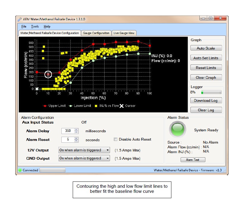
3. With a baseline flow curve now established, click on Auto Set Limits and the software will produce its best suggested high and low flow limit lines based on the populated flow data shown on the graph.

4. Review and adjust the high and low flow limit lines as needed to contour the lines around the baseline flow curve by clicking and dragging on a break point. Once a break point is selected you can also move left and right using the arrow keys and then move the break point up or down. Pressing the Tab key will toggle back and forth between the high and low limit lines.
5. Test the configuration using your anticipated normal operating conditions with varying injection progression rates to account for starting, stopping, accelerating, high boost, low boost, tip in, fast shifts, slow shifts, etc. If false triggers occur either adjust the high or low flow curve up or down at the injection percentage where the alarm occurred or adjust the Alarm Delay setting.
There are two general configuration strategies to follow when using the Water/Methanol Failsafe. The high and low flow limit lines can be set very tightly to the baseline flow curve and a longer Alarm Delay can be used. Conversely, the high and low flow limit lines can be set further way from the baseline flow curve and a shorter Alarm Delay can be used. All injection systems are different and only thorough configuration testing will reveal which strategy is best for your application.
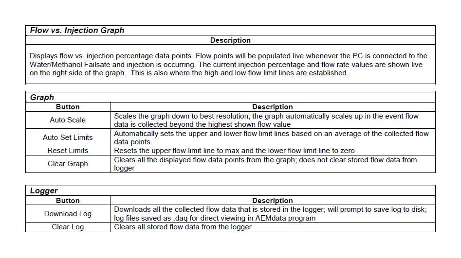
DATA LOGGER
The Water/Methanol Failsafe has an internal logger that can store approximately 2.5 minutes of injection data. The logger maintains two levels of data logs. First, all flow data points are stored and downloadable for viewing on the Flow vs. Injection Graph in the Water/Methanol Failsafe Configuration tab. Second, all injection events, inputs, outputs, and alarm triggers are logged in special log file format for viewing with the AEMdata software that comes as part of the Water/Methanol Failsafe download package. Once the logger memory has filled up, the logger will begin to loop log and the oldest data will be discarded as new data is collected.
Logging will start when Injection Percentage is more than 5% and stop when Injection Percentage is less than 5%. Each individual injection event is indicated by a marker.
The following is a basic guideline on how to use the internal data logger.
1. Connect USB cable to PC. In the Water/Methanol Failsafe Configuration tab under Logger, click Download Log. All logged flow data points will now be displayed in the Flow vs. Injection Graph.
2. To download the log to the PC click Yes when prompted to save data to disc and then save log in desired location.
3. Click Yes when prompted to open file in AEMdata.
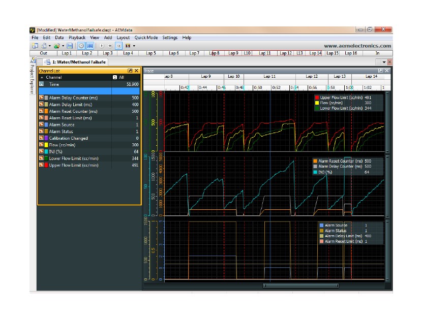
4. The saved data log is now shown in a special log viewing template that is pre-loaded into AEMdata.
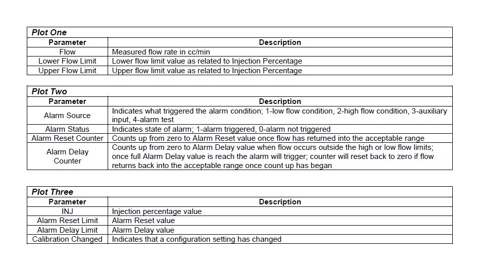
The data log will now open and be displayed in three separate plots as described on page 12.
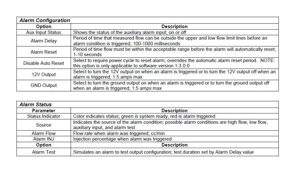
OUTPUT CONFIGURATION
The Water/Methanol Failsafe has two outputs that are triggered when an alarm condition exists; one 12 volt (high side) output and one ground (low side) output. These outputs can be used in a multitude of ways to reduce boost, pull timing, or otherwise protect an engine in the event there is a problem with the water/methanol injection system. The following is an index of possible auxiliary devices that can be triggered by the alarm outputs:
NC/NO Relay
The following are examples of how a NC/NO relay (Bosch PN 0-332-019-203 or similar) can be configured for use with the Water/Methanol Failsafe.
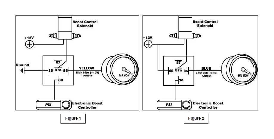
Signal Interrupt − The high side (12 volt) output from the Water/Methanol Failsafe can be used to turn on a NC (normally closed) relay and interrupt the output signal from a boost controller to its boost control solenoid – see Figure 1. Conversely, the low side (ground) output can also be used to trigger the relay − see Figure 2.
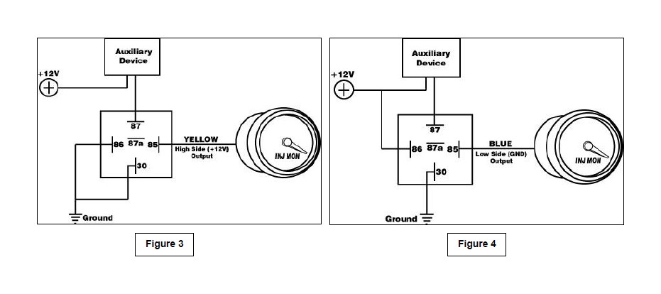
Auxiliary Device − The high side (12 volt) output from the Water/Methanol Failsafe can be used to turn on a NO (normally open) relay and activate or deactivate an auxiliary device that can be used to reduce timing or boost or control some other function when the current requirement is greater than 1.5 amps – see Figure 3. Conversely, the low side (ground) output can also be use to trigger the relay − see Figure 4.
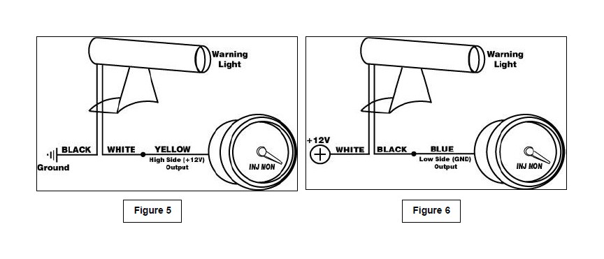
Warning Light
The Water/Methanol Failsafe can also be used to directly activate a warning light (Autometer PN 3239 or similar). Connect the warning light black wire to ground and power the light with the high side output – see Figure 5. Alternatively, the low side output can also be used to turn the light on if the white wire is connected to 12V – see Figure 6.
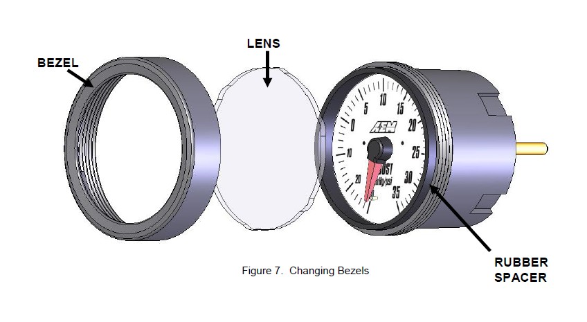
WATER/METHANOL FAILSAFE GAUGE
The Water/Methanol Failsafe gauge comes with the black bezel installed however, a silver bezel is also included. To change the bezel, orient the gauge so you are looking at the faceplate. Rotate the bezel counter-clockwise to unscrew it from the gauge cup. The bezel, lens, and rubber spacer are all removable. Reassemble the gauge as shown below in Figure 7. Note: When reassembling the gauge, it may be necessary to apply a light amount of pressure on the lens and spacer to keep the faceplate from rotating when reinstalling the bezel. Do not over tighten the bezel when reassembling the gauge.
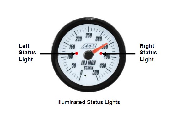
Status Lights
The Water/Methanol Failsafe gauge has two status lights (see below) that indicate when an alarm has been triggered. The left status light will turn on if there is a low flow alarm. The right status light will turn on if there is a high flow alarm. Both status lights will turn on if the auxiliary input is triggered.
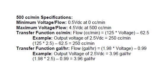
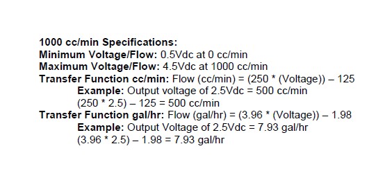
Analog Output
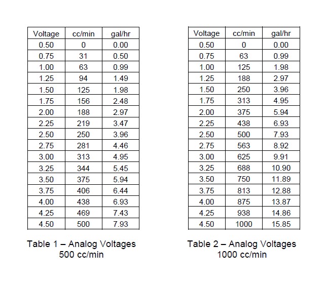
The analog output from the Water/Methanol Failsafe is a linear dc voltage signal that varies with flow. The signal is used for sending information to a data logger or an engine management system like the AEM EMS or F/IC. The output range is automatically scaled when either the 500 cc/min or 1000 cc/min flow range is selected in the Gauge Configuration tab. The transfer functions for the analog output of each flow range are listed below in cc/min and gal/hr.
A list of output voltages and corresponding flow rates is shown on Page 17 - Table 1.
A list of output voltages and corresponding flow rates is shown on Page 17 - Table 2.
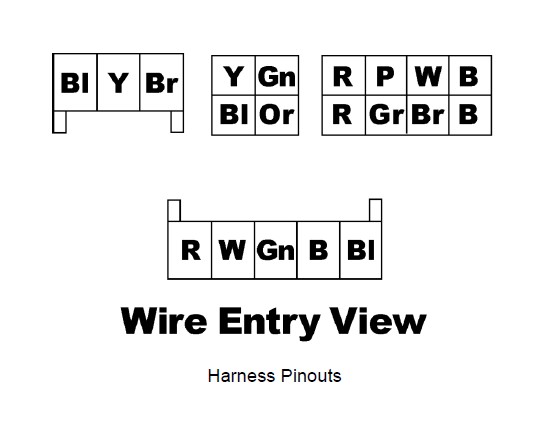
Connector Pinouts
The pinouts for the 3-pin sensor harness, 4 pin I/O harness, 8-pin power harness, and 5 pin USB harness are provided below.