FREE 1 to 3-Day Delivery on Orders $149+ Details
How to Install AEM Electronics Infinity Plug & Play Engine Harness Adapter (11-14 GT, BOSS) on your Ford Mustang

Shop Parts in this Guide
WARNING: This installation is not for the tuning novice! Use this system with EXTREME caution! The AEM Infinity Programmable EMS allows for total flexibility in engine tuning. Misuse or improper tuning of this product can destroy your engine! If you are not well versed in engine dynamics and the tuning of engine management systems DO NOT attempt the installation. Refer the installation to an AEM-trained tuning shop or call 800-423-0046 for technical assistance.
NOTE: All supplied AEM calibrations, Wizards and other tuning information are offered as potential starting points only. IT IS THE RESPONSIBILITY OF THE ENGINE TUNER TO ULTIMATELY CONFIRM IF THE CALIBRATION IS SAFE FOR ITS INTENDED USE. AEM holds no responsibility for any engine damage that results from the misuse or mistuning of this product!
OVERVIEW
The 30-3813 AEM Infinity Coyote Engine Harness Adapter was designed to run the 2011-2014 Ford 5.0L 4V Ti- VCT Coyote engines and Ford Racing Crate Engines part numbers M-6007-M50 and M-6007-A50NA; all with manual transmissions. This is a true standalone system that eliminates the use of the Ford ECU and mass airflow sensor. The use of this harness makes the kit “plug and play” so no cutting or splicing wires is necessary (when used with optional 30-3510-00 AUX harness, sold separately). The base configuration files available for the Infinity EMS are starting points only and will need to be modified for every specific application.
The available Infinity EMS part numbers for this adapter kit are:
· 30-7101 INFINITY-8
· 30-7100 INFINITY-10
Please read this document in its entirety before attempting to start or run an engine.
GETTING STARTED
Refer to the 10-7100 for EMS 30-7100 Infinity Quick Start Guide for additional information on getting the engine started with the Infinity EMS. The Ford Coyote V8 base session is located in C:\Documents\AEM \Infinity Tuner\Sessions\Base Sessions.
DOWNLOADABLE FILES
Files can be downloaded from www.aeminfinity.com. An experienced tuner must be available to configure and manipulate the data before driving can commence. The Quick Start Guide and Full Manual describe the steps for logging in and registering at www.aeminfinity.com. These documents are available for download here: http://www.aemelectronics.com/products/support
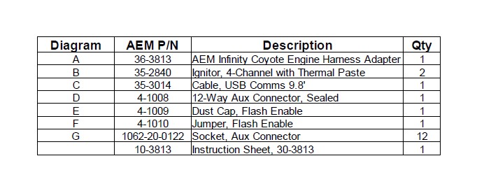
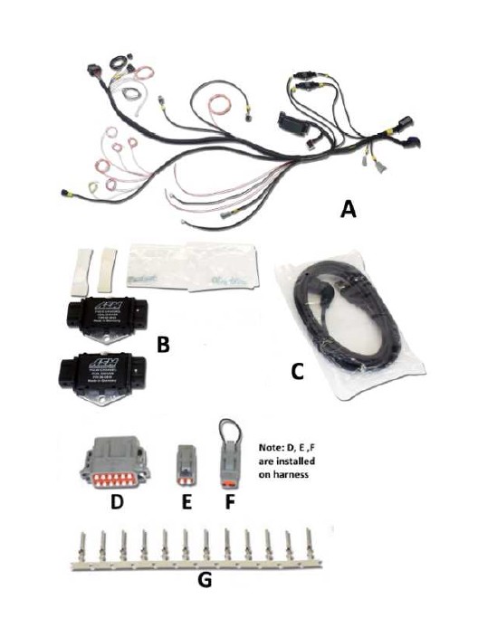
Kit Contents
Important Application Notes
The 30-3813 AEM Infinity Coyote Engine Harness Adapter allows for a "plug and play" installation of either an AEM Infinity-8 or Infinity-10 ECU to a 2011-2014 Ford 5.0L 4V Ti-VCT Coyote Engine with a manual transmission. These engines are available as crate engines from Ford Racing by the following part numbers:
5.0L 4V Ti-VCT Mustang Crate Engine - Ford Racing P/N M-6007-M50
5.0L Coyote Aluminator NA Crate Engine - Ford Racing P/N M-6007-A50NA
5.0L Coyote Aluminator SC Crate Engine - Ford Racing P/N M-6007-A50SC
5.0L Aluminator XS Crate Engine - Ford Racing P/N M-6007-A50XS
Both of these crate engines come with an engine wiring harness that plugs directly into the AEM wire harness. The AEM Infinity Coyote Engine Harness Adapter includes a fused power distribution module with relays for radiator fan, coils, injectors, ECU, starter solenoid, and fuel pump.
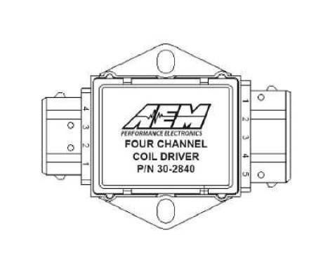
The OEM Ford two-wire ignition coils (Motorcraft P/N BR3Z-12029-A) are controlled by the AEM Infinity ECU, but they are not driven directly. This kit includes the two AEM 4 Channel Coil Drivers (AEM P/N 30-2840) required to drive these coils.
The AEM Infinity ECU will run the engine with a speed density fueling calculation, eliminating the need for an OEM airbox and mass airflow sensor (MAF). Required are an intake air temperature (IAT) sensor and manifold absolute pressure (MAP) sensor. AEM also offers an auxiliary sub-harness to make adding these sensors a plug and play installation.
30-2010 Air Temp Sensor Kit, 3/8" NPT
30-2130-50 3.5bar (50PSIa) Stainless Steel MAP Sensor Kit
30-3510-00 Auxiliary Harness for AEM MAP and IAT Sensors
The AEM Infinity ECU includes on board control for two UEGO wideband oxygen sensors. These sensors (sold separately, 2 required) plug in directly to the AEM Infinity Coyote Engine Harness Adapter.
30-2001 Bosch LSU 4.2 Wideband UEGO Replacement Sensor
The AEM Infinity ECU includes Electronic Throttle Control (ETC) that will control the electronic throttle body included with the above crate engines. A suitable ETC accelerator pedal is required. The base session file for the Ford Coyote application is configured to use the Ford Mustang accelerator pedal (sold separately) and the AEM Infinity Coyote Engine Harness Adapter is designed to plug directly into this accelerator pedal.
Ford P/N BR3Z-95836-D Accelerator Pedal
The base
file provided for the Ford Coyote application was created with the use of the Ford Racing Mustang Boss 302 Alternator Kit. The calibration has Lowside 0 duty and frequency tables setup to charge at ~14.7 volts. See "Alternator Control" section for more information on controlling the charging system. The AEM Infinity Coyote Engine Harness Adapter is designed to plug directly into this alternator.
Ford Racing P/N M-8600-M50BALT Mustang Boss 302 Alternator Kit
The base calibration utilizes the Clutch Position (Neutral Switch) flying lead as an input into the Infinity ECU. Once grounded, the Infinity ECU provides the ground for the Starter Relay control circuit. If the user wishes not to provide a ground to this flying lead, follow the steps provided in the "Clutch Position Switch" section to modify the LS8_Duty [%] table values to allow the starter to be engaged without a clutch signal.
The factory Cylinder Head Temperature sensor and fuel injectors have been fully characterized and their calibrations are utilized in the base calibration.
INFINITY ADAPTER HARNESS
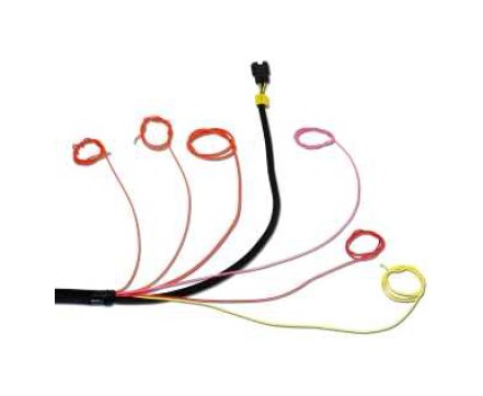
The core of the AEM Infinity Coyote Engine Harness Adapter is the main harness that connects between the Ford engine harness and the AEM Infinity ECU. This harness features a power distribution module that includes fuses and relays to properly power the engine and related accessories. The harness connections for the various power, ground, switches, and sensors are described here. The harness may be broken up into several "branches" as described in the following diagram to simplify installation.
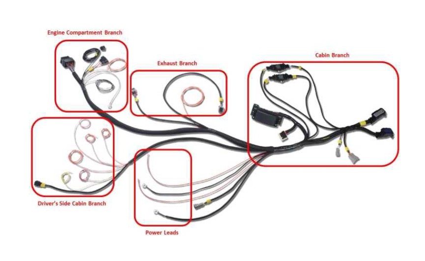
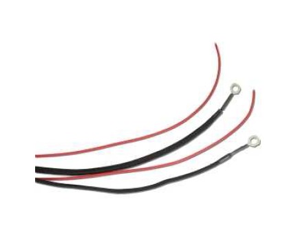
Power Leads
12V BATT - Two red 10ga main power flying leads should be connected to the battery positive terminal.
Ground - Two ring terminals should be securely attached to chassis ground. Remove paint or plating at the attachment point of these ring terminals. Verify that you have a good reliable ground path from the battery negative post to the location being used for these ring terminals. In general, the the resistance from the battery ground to this chassis location should be less than 0.1 Ohm.
Driver's Side Cabin Branch
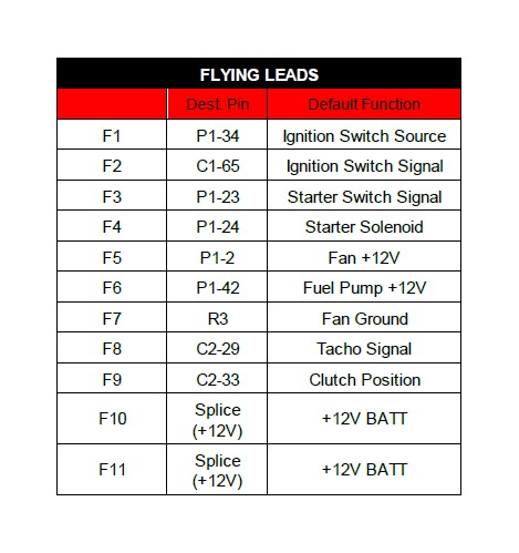
IGN SW SOURCE - Red 18ga flying lead should be connected to the "B" or "BATT" battery source terminal of the ignition switch.
IGN SW SIGNAL - Orange 18ga flying lead should be connected to the "IGN" terminal of the ignition switch. This must be a single terminal on the ignition switch that provides 12V when the key is in both the 'Start' (cranking) and 'Run' position.
START SW SIGNAL - Orange 18ga flying lead should be connected to the "START" terminal of the ignition switch. This must be a single terminal on the ignition switch that provides 12V when the key is in the 'Start' (cranking) position only.
FUEL PUMP 12V - Orange 12ga flying lead should connect to fuel pump positive terminal. Separate ground for fuel pump must be provided. This provides for ECU control of the fuel pump- running when Engine RPM > 0 and two second prime at key-on.
CLUTCH POS - Yellow 18ga flying lead should be grounded through a customer-supplied clutch position switch when the clutch pedal is depressed. The starter solenoid safety lockout function may be bypassed via Infinity Tuner software if the user chooses not to use a clutch switch. The lead should be insulated and tied up out of the way if unused. See 'Clutch Position Switch' section for details.
TACHO - Pink 18ga flying lead may be used to drive a standard tachometer with a 12V square wave signal. This is not a mandatory function, the lead should be insulated and tied up out of the way if unused.
APP - The Accelerator Pedal Position sensor branch terminates with a connector that plugs directly into a customer-supplied accelerator pedal assembly, Ford P/N BR3Z-95836-D.
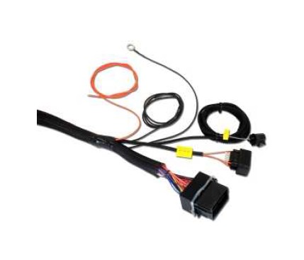
Engine Compartment Branch
PCM 70-WAY - This 70-way terminated connector plugs into the engine wire harness supplied with the Ford Racing crate engine. The engine harness side of this connection includes a white plastic latch that swings over and locks into position when the connection is fully seated.
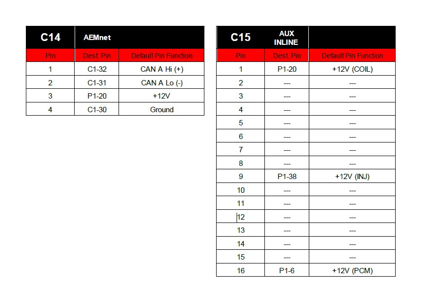
AUX INLINE to ENGINE - This 16-way terminated connector plugs into the engine wire harness supplied with the Ford Racing crate engine. It is normal for this connector to have only three wires in it. The remainder of the unused positions are sealed with blanking plugs.
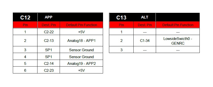
ALT - This 3-way terminated connector plugs directly into a customer-supplied alternator, Ford Racing P/N M-8600- M50BALT. The AEM Infinity ECU controls the voltage set point of the alternator, see 'Alternator Control' section for details.
FAN 12V - Orange 12ga flying lead should connect to radiator fan positive terminal. This provides for ECU control of the electric radiator fan, adjustable on/off temperature configurable via Infinity Tuner Setup Wizard.
FAN -GND - Black 12ga flying lead should connect to radiator fan negative terminal. This wire terminates at the adjacent ring terminal.
Ring Terminal - Black 12ga lead provides ground to the electric radiator fan. Remove paint or plating at the attachment point of this ring terminal. Verify that you have a good reliable ground path from the battery negative post to the location being used for this ring terminal. In general, the the resistance from the battery ground to this chassis location should be less than 0.1 Ohm.
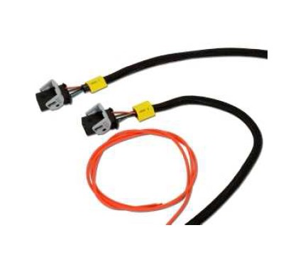
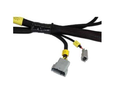
Exhaust Branch
UEGO 1 - This 6-way terminated connector plugs directly into a customer-supplied wideband oxygen "UEGO" sensor, AEM P/N 30-2001. This sensor should be mounted in the exhaust collector of Bank 1 (cylinders 1-2-3-4), typically passenger side of the vehicle. Proper cylinder sampling is critical for closed loop air fuel ratio control.
UEGO 2 - This 6-way terminated connector plugs directly into a customer-supplied wideband oxygen "UEGO" sensor, AEM P/N 30-2001. This sensor should be mounted in the exhaust collector of Bank 2 (cylinders 5-6-7-8), typically driver side of the vehicle. Proper cylinder sampling is critical for closed loop air fuel ratio control.
STARTER SOL - Orange 12ga flying lead should be connected to the starter solenoid. The use of a clutch position switch allows for the use of ECU-controlled starter solenoid safety lockout function. This function may be bypassed via Infinity Tuner software if the user chooses not to use a clutch switch. See 'Clutch Position Switch' section for details.
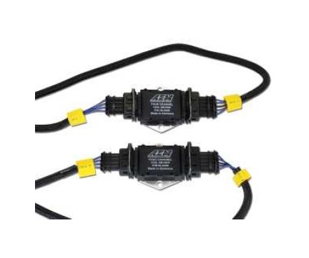
Cabin Branch
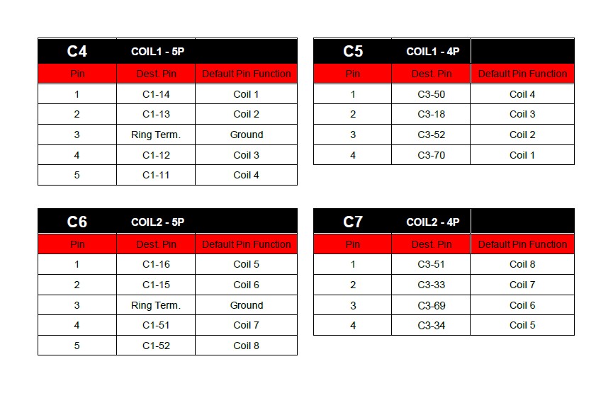
Coil 1 - There is a pair of terminated branches marked 'Coil 1'- one 4-way and one 5-way connector. These connectors should be plugged into opposite ends of the same 4-Channel Ignitor, provided in this kit. See '4-Channel Ignitors' section for mounting requirements.
Coil 2 - There is a pair of terminated branches marked 'Coil 2'- one 4-way and one 5-way connector. These connectors should be plugged into opposite ends of the same 4-Channel Ignitor, provided in this kit. See '4-Channel Ignitors' section for mounting requirements.
Flash - This 2-way connector is used for secondary hardware flashing. This connector is normally protected with a dust cap. The included shunt connector jumps the two wires together when required. Once initially flashed, the EMS is normally upgraded in the software, not requiring this connector.
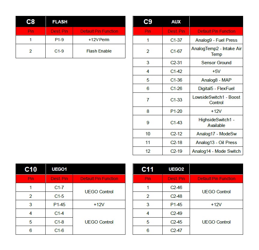
AUX - This 12-way connector is used to adapt many common ancillary inputs and outputs easily. Included in this kit are a 12-way mating connector, 12 terminals, and a connector wedgelock. These components will need to be terminated by the installer with 16-22ga wire. For a plug & play installation of the MAP and IAT sensors required to run this engine, use the Auxiliary Harness AEM P/N 30-3510-00 (sold separately). This will allow the installer to plug in the required sensors with out any custom wiring or termination. Note: the pin numbering is molded into the wire side of the connector. See 'Pinouts' section for details of this connector's pins.
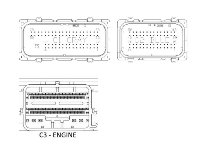
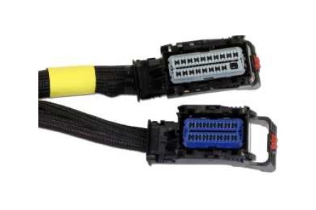
ECU C1 - This 73-way connector should be plugged directly into the AEM Infinity ECU. This ECU is identified by the gray terminal position lock, and mates to the gray connector on the ECU.
ECU C2 - This 56-way connector should be plugged directly into the AEM Infinity ECU. This ECU is identified by the blue terminal position lock, and mates to the blue connector on the ECU.
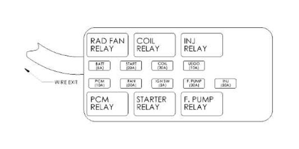
Power Distribution Module - The PDM contains the fuses and relays required for operation of the engine, fuel pump, starter solenoid, and electric radiator fan. Always replace fuses and relays with components of an identical rating. Refer to the diagram at right for fuse values and component locations.
4-Channel Ignitors
It is critical that this driver module be mounted to a flat metallic surface and that the supplied thermally conductive grease is applied between the module and its mounting surface. This is required to allow the heat generated to be conducted away. Failure to mount the driver in this manner will cause a premature failure and will void the warranty.
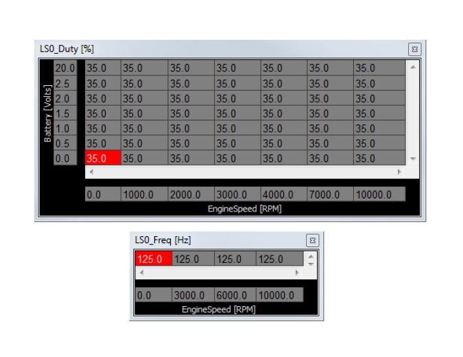
Alternator Control
The Ford Mustang Boss 302 Alternator is controlled by a fixed frequency and a variable duty cycle that controls the charge voltage set point. The base session sets LS0_Duty to 35 % which correlates to ~14.7v charge. Decreasing the LS0_Duty percentage will increase the battery set point (higher voltage), and increasing the duty percentage will decrease the battery set point (lower voltage).
Clutch Position Switch
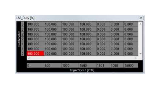
The base session will not provide a ground for the Starter Solenoid relay unless a ground is provided to the CLUTCH POS flying lead on the Ford Racing wiring harness. This requirement can be modified through setting the LS8_Duty [%] table to 100% at all ClutchSwitch positions. See example below:
The base session sets the input for the ‘ClutchSwitch’ 1D table channel to Analog20, which is pulled up to 5 volts. When a ground is provided this drops Analog20’s voltage from 5 volts to 0 volts, this transition in voltage sets the ClutchSwitch channel to 0 (OFF) or 1 (ON).
Drive By Wire
The base calibration will set most of the Drive-By-Wire (DBW) channels for the stock 5.0L Coyote throttle body. If a different throttle body is used, for example Cobra Jet, then further adjustments to the DBW channels will be required. To complete the DBW setup the Drive By Wire Wizard must be ran.
Select Calibrate sensor data only and follow the DBW Setup steps.
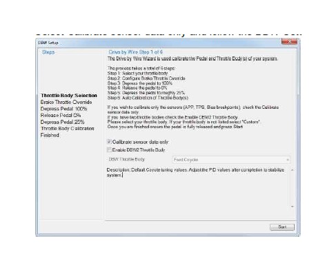
Note: There are a few integrated DBW fail safes incorporated into the Infinity system. For instance, if the accelerator pedal and throttle position sensors do not track each other, or if the maximum DBW current is exceeded, there will be a fatal error which will kill the engine for safety purposes. This error will reset when the ignition key is turned off momentarily, and then turned back on.
Variable Valve Control (VVC)
The AEM Infinity system supports Fords Coyote’s Ti-VCT Variable Valve Control. The base calibration is configured with base VVC settings that should work for most stock engines.
To ensure proper Ti-VCT function, the user must sync the cam timing by following the instructions listed in Setup Wizard: Wizards>Setup Wizard>VVC>VVC Cam Sync. Failure to properly sync the cam timing may result in an improperly functioning Ti-VCT system.
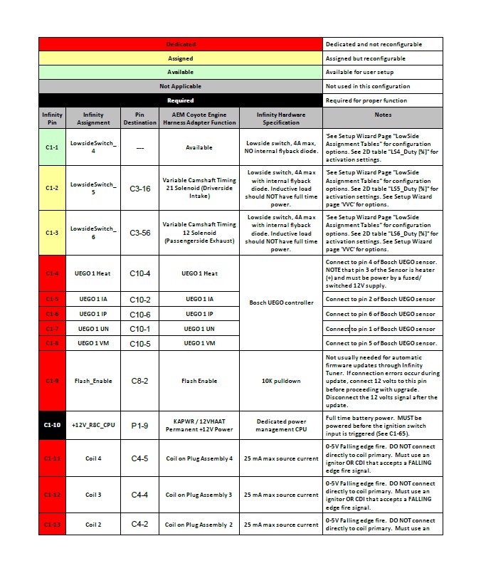
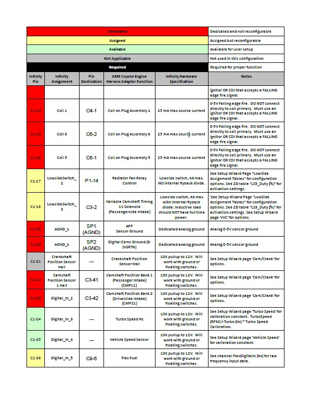
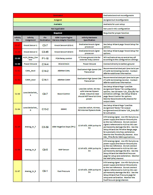
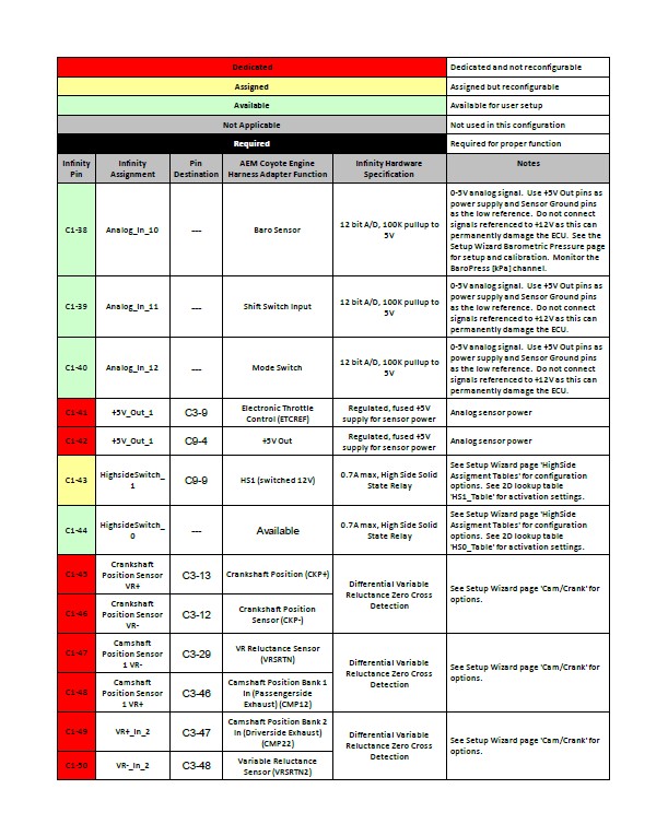
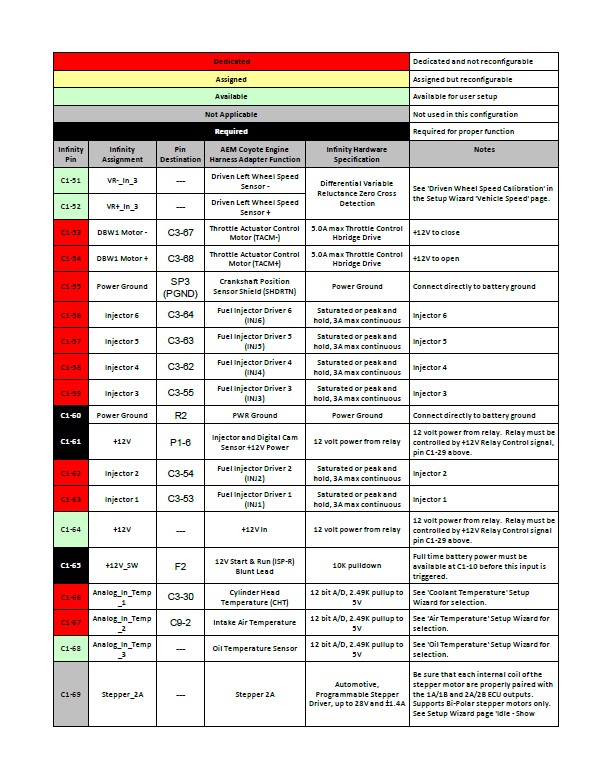
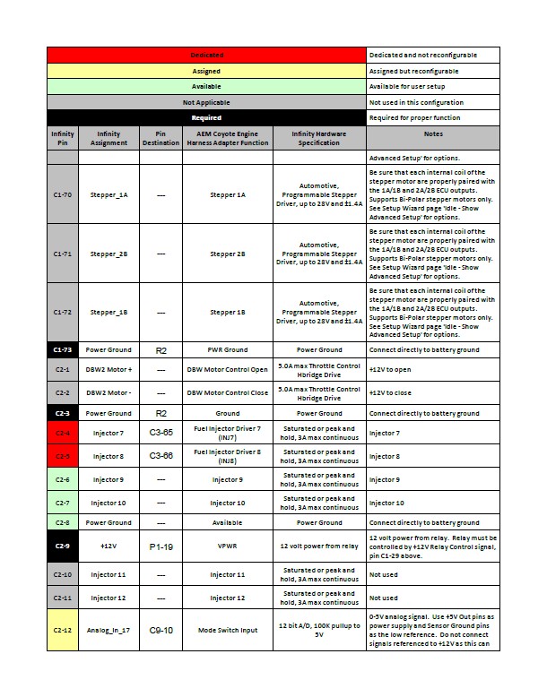
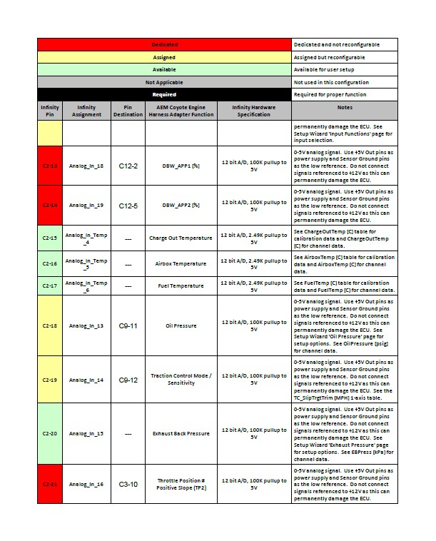
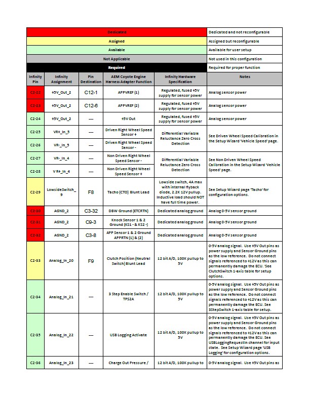
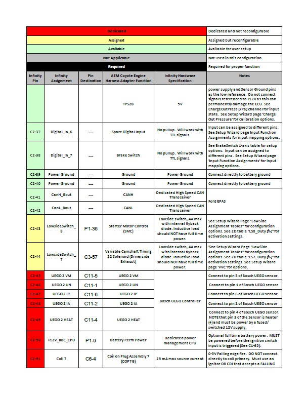
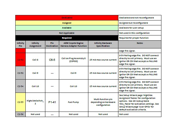
PINOUTS