FREE 1 to 3-Day Delivery on Orders $149+ Details
How to Install Aeromotive High Flow Fuel Rail Kit (86-95 GT, Cobra) on your Ford Mustang
Installation Time
3 hours
Tools Required
- Fuel supply line quick disconnect tool
- Fuel return line quick disconnect tool
Shop Parts in this Guide
CAUTION:
Installation of this product requires detailed knowledge of automotive systems and repair procedures. We recommend that this installation be carried out by a qualified automotive technician.
Installation of this product requires handling of gasoline. Ensure you are working in a well ventilated area with an approved fire extinguisher nearby. Extinguish all open flames, prohibit smoking and eliminate all sources of ignition in the area of the vehicle before proceeding with the installation.
When installing this product, wear eye goggles and other safety apparel as needed to protect yourself from debris and sprayed gasoline.
WARNING!
The fuel system is under pressure. Do not open the fuel system until the pressure has been relieved. Refer to the appropriate vehicle service manual for the procedure and precautions for relieving the fuel system pressure.
The enclosed Aeromotive fuel rails are intended to be installed on an unmodified OEM intake manifold of the identified application. Aeromotive cannot guarantee the proper fitment on aftermarket intake manifolds and the end user is responsible for verifying proper fitment and assumes all liability.
Aeromotive system components are not legal for sale or use on emission controlled motor vehicles.
Supplies needed:
Vehicle service manual
Upper intake gasket
Fuel injector replacement O-rings
Light oil
Solvent parts cleaner
Clean shop towels
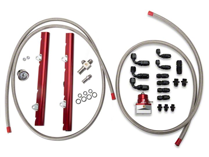
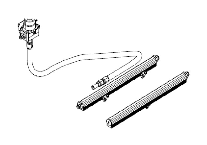
This kit contains the following parts:
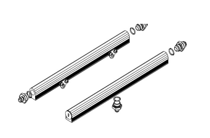
1ea p/n 14101 Ford 5.0L Fuel Rails
1ea p/n 13109 EFI Regulator
1ea p/n 15101 AN-06 Return Line Adapter Fitting
1ea p/n 15102 AN-08 Supply Adapter Tee Fitting
3ea p/n 15606 ORB-06 to AN-06 Port Fitting
2ea p/n 15607 ORB-08 to AN-08 Port Fitting
2ea p/n 15605 ORB-08 to AN-6 Port Reducer
3ea p/n 15621 –6 O-Ring
4ea p/n 15622 –8 O-Ring
4ea p/n 15650 –6 Straight Hose End
2ea p/n 15652 –6 90-Degree Hose End
1ea p/n 15653 –8 Straight Hose End
3ea p/n 15655 –8 90-Degree Hose End
8ft –6 Stainless Steel Braided Fuel Line
6ft –8 Stainless Steel Braided Fuel Line
The following steps are typical of most installations:
1. Once the engine has been allowed to cool, disconnect the negative battery cable and relieve fuel system pressure, referring to the appropriate vehicle service manual for the procedure on doing so.
2. Remove the air intake ducting from the throttle body and position it out of the way.
3. Note the location of and remove any vacuum lines connected to the upper intake manifold and position them out of the way.
4. Remove the throttle cable from the throttle body; referring to the appropriate vehicle service manual for the procedure for doing so.
5. Unplug the TPS sensor, which is typically located on top of the throttle body.
6. Remove the nameplate on the top of the upper intake manifold by removing 4 screws.
7. Remove the upper intake manifold bolts (Typically there are 6 of them).
8. Gently remove the upper intake from the engine. Place clean shop towels into or tape up the lower intake ports to prevent any material from entering the intake.
9. Carefully clean the old gasket material from both manifolds, while preventing any debris from entering the intake manifold ports.
10. Check for any dirt or debris around the fuel injectors. If any is evident, wash it off with some solvent parts cleaner or wipe it off with a clean shop towel.
11. Disconnect the electrical connector at each injector, making note of the location of each.
12. Disconnect both the supply and return fuel lines from the OEM fuel rails. These lines are attached by a special quick disconnect fitting which requires a special tool for removal. Place clean shop towels around the open fuel lines to catch any gasoline that may drip out and to prevent any dirt from entering the fuel lines.
13. Remove the vacuum line from the fuel pressure regulator.
14. Remove the bolts that attach the fuel rail to the lower intake (Typically there are 4 of them).
15. Place clean shop towels around the injectors to catch any gasoline that may be spilled during their removal. Remove the injectors from the manifold by gently pulling upward on the fuel rail / injector assembly. Keep all injectors connected to the fuel rails. If an injector does pull out of the fuel rail, it may spill a large amount of fuel.
Failure to satisfy all safety considerations will result in fire, explosion, injury and/or loss of life to yourself and/or others.
16. Carefully remove the fuel injectors from the OEM fuel rail.
17. Remove the old o-rings from the fuel injectors, inspect the injectors for any dirt or debris and clean if needed. It is suggested that the old o-rings be replaced, contact your local parts store or dealer to purchase the correct replacement o-rings.
18. Carefully install the new fuel injector o-rings on the injectors
When installing o-rings it is important to place a small amount of light oil on both the o-ring and the mating surface to ease installation and prevent damaging the o-ring.
19. Place a thin coat of light oil in the fuel rail fuel injector bores and in the lower intake manifold injector bores to help prevent cutting the o-rings during installation.
20. Carefully place the fuel injectors in the fuel rails. Position the electrical connector on each fuel injector to the opposite side of the fuel rail as the mounting bracket.
21. Install the fuel rail that has an ORB-08 port plug in one end on the driver side, with the port plug facing the front of the vehicle. This kit comes with 2 aluminum spacers which get installed between the lower intake manifold and the fuel rail brackets. In some instances it will be required to install additional flat washers to space the rail out further from the distributor. After insuring that the injectors are properly seated in the intake manifold injector bores, install the driver side fuel rail mounting bolts, insuring that the fuel rail spacers are captured between the fuel rail bracket and the lower intake manifold.
22. Install the passenger side fuel rail, being careful not to cut any of the o-rings during installation (This fuel rail does not require any spacers between the fuel rail bracket and the lower intake).
23. With the Aeromotive fuel rail properly secured to the intake manifold, Move the fuel injector vertically downward until it bottoms out on the intake manifold, In this downward position, inspect the upper fuel injector o-ring (on the fuel rail side) and insure it is fully covered by the fuel rail injector bore. If any of the o-ring is exposed, loosen the fuel rail bracket screws and adjust the installation height until the oring is no longer exposed and retighten the bracket screws. In the situation where the fuel injector has no vertical travel, either the fuel rail brackets can be adjusted or the brackets shimmed until the fuel injector fits freely. Do not pressurize the fuel rail until the proper fuel rail installation height is achieved.
24. Find suitable place in the vehicle’s engine compartment to mount the Aeromotive regulator, typically on the passenger side inner fender or shock tower. Using the supplied mounting bracket as a template, mark the bracket mounting holes and drill to accept a #10 screw.
25. With the bracket attached to the regulator, mount the bracket and regulator to the vehicle using two #10 screws, nuts and lock washers.
26. Install one ORB-06 o-ring on the cut-off side of each of the three 15606 ORB-06 to AN-06 port fittings.
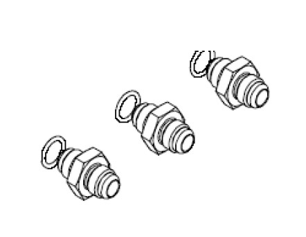
27. Thread the port (o-ring) side of the 15606 port fittings into each of the three ORB-06 ports on the regulator.
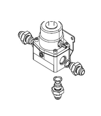
28. Install one ORB-08 o-ring on the port side of each of the two 15607, ORB-08 to AN-08 port fittings.
29. Install on AN-08 o-ring on the AN-08 cutoff side of each of the two AN-08/AN-6 reducer unions.
30. Thread the o-ring side of each two 15607, ORB-08 to AN-08 port fittings into the back of each fuel rail.
31. Thread the o-ring side of one of the ORB-08 to AN-06 reducer fittings into the front of the passenger’s side fuel rail. Thread the remaining fitting into the bottom center of the driver’s side fuel rail.
32. Inspect the o-rings on the OEM quick disconnect fitting and replace if necessary. Coat o-rings and the adapter fitting with a light oil and install the 15101 AN-06 Ford quick disconnect adapter fitting on the OEM return fuel line.
Please note if installing a high performance fuel pump, (Similar to Aeromotive P/N 111-01-BF) the OEM return line will be too restrictive to handle the volume of fuel that these pumps are capable of pumping. To prevent loosing lower pressure adjustablity of your regulator it will be necessary to replace the OEM return line with a 3/8” ID (AN-06) return line in these cases.
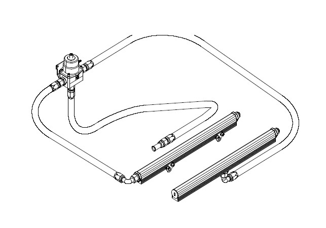
33. This kit contains one AN-06 straight hose end which will connect to the OEM fuel line adapter fitting and one AN-06 90 degree hose end, to connect to the AN-06 port fitting in the bottom of the fuel pressure regulator. With these fittings in place, measure the length of fuel line needed. See section titled Hose and Fitting Assembly for fuel line assembly instructions. Once the hose is assembled, ensure there is no debris in the hose and install it.
34. A typical application looks similar to the picture shown below.
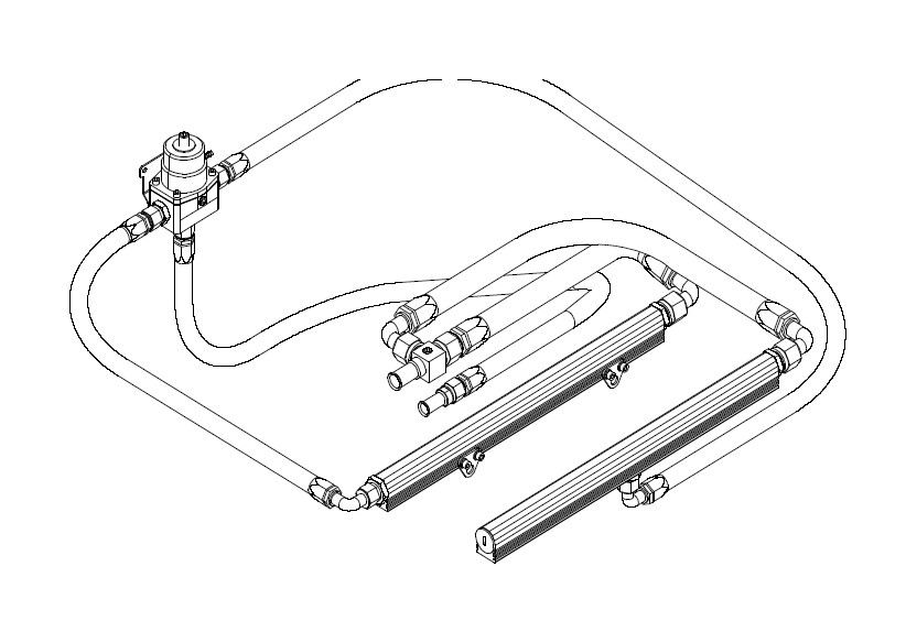
35. Connect one AN-06 straight hose end to each of the two ports on the fuel pressure regulator. Connect one AN-06 90-degree hose end to each of the ORB-08 to AN-06 reducer fittings in the fuel rails. Plan a route for each of the two lines between the fuel pressure regulator and the fuel rails, measure the two lengths of fuel line needed. See section titled Hose and Fitting Assembly for fuel line assembly instructions. Once the hoses are assembled, ensure there is no debris in the hose and install them.
36. Inspect the OEM fuel supply line o-rings and replace if necessary. Place a light coat of oil on the fuel supply line o-rings and the supply line adapter fitting to ease installation. Connect the 15103 AN-08 tee adapter fitting to the OEM quick connect on the fuel supply line.
37. Using the remaining AN-08 hose end fittings as a guide, measure the required fuel line lengths needed and make up the last two required AN-08 fuel supply lines (See section titled Hose and Fitting Assembly). A typical configuration is pictured below.
38. Reassemble the vehicle using the reverse of the foregoing removal procedure.
Please note, due to the wide range of applications and varying OEM and after market component tolerances it has been found in a few isolated cases it is necessary to install a 3/8” thick spacer between the upper and lower intake manifolds. This will allow you to gain clearance between the top of the fuel rails and the bottom of the upper intake manifold. These spacers are readily available from your local speed shop or mail order warehouse.
39. Remove the 1/8 NPT pipe plug from the either the fuel pressure regulator or fuel supply adapter tee fitting and attach a suitable fuel pressure gauge. Ensure that any spilled gasoline and any gasoline soaked shop towels are cleaned up and removed from the vicinity of the vehicle!
40. Reconnect the battery and turn the ignition to the ON position WITHOUT starting the car. After several seconds, check the fuel pressure. If there is no fuel pressure, turn the ignition key to the OFF position, wait one minute, return the ignition to the ON position, and recheck the fuel pressure. Repeat this ignition OFF and ON procedure until the fuel pressure gauge registers fuel pressure.
41. With the fuel pressure gauge registering fuel system pressure, check for fuel leaks from and around the Aeromotive regulator, fuel rails, all fuel lines and connections! If any fuel leaks are found, turn the ignition key to the OFF position, remove any spilled fuel and repair the leak before proceeding!
42. Once the fuel pressure gauge registers fuel system pressure and there are no fuel leaks, start the engine and adjust the regulator to the desired fuel pressure. Turning the adjustment screw clockwise will increase fuel pressure. OEM Ford regulators are typically set at approximately 38-40 psi, without the vacuum line attached. The fuel pressure adjustment range for this regulator is 35-75 psi. and we recommend setting the static pressure (no vacuum) at
43 psi as a starting point. 43. Detailed information on tuning EFI engines with fuel pressure is available on Aeromotive’s website, in the Tech Help Section, under Tech Bulletins. Please See Tech Bulletin TB-902, titled: Advanced Tips for EFI Tuning with Fuel Pressure TB-902. Due to the confined nature of modern OEM vehicles Aeromotive realizes that the fuel pressure regulator may be inconvenient to adjust in some applications. We feel that this small inconvenience is worth it in providing you with an optimal fuel system.
44. Once the desired fuel pressure is achieved, tighten the regulator adjustment jam nut and attach the vacuum line.
45. Turn off the engine and allow it to cool. If you do not want to keep the fuel pressure gauge on the vehicle, relieve the fuel system pressure as instructed in the appropriate vehicle service manual. Remove the fuel pressure gauge and reinstall the 1/8 NPT pipe plug, using thread sealant.
46. Test drive the car to insure proper operation and re-check the fuel system for leaks. If any leaks are found, immediately shutoff the engine and repair the leak(s)!
Hose and Fitting Assembly
CAUTION: When assembling this product, wear eye goggles and other safety apparel as needed to protect yourself from debris and sharp edges.
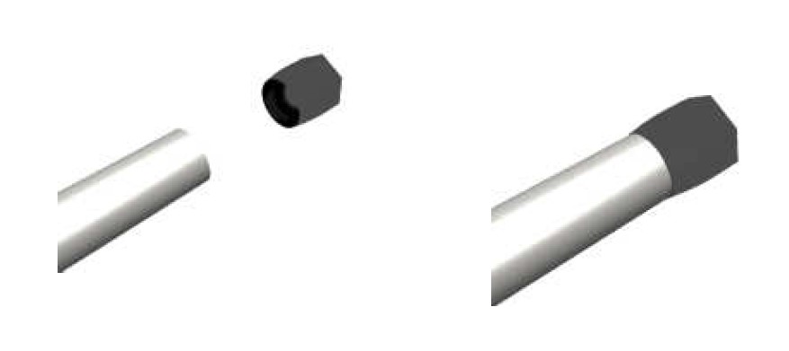
A. Wrap hose with masking tape at desired cutoff length. Cut hose through masking tape squarely to desired length using a cut-off machine or a fine tooth hacksaw. Remove the masking tape.
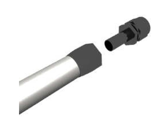
B. Unthread the hose socket from the rest of the hose end fitting.
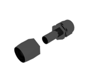
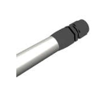
C. Insert hose in the socket with a twisting and pushing motion until the hose is fully seated in the socket.
D. Using a grease pencil, marker or tape, mark the location of the hose in relation to the hose socket which you just installed.
E. Using a light oil lubricate the inside of the hose and the hose end mating parts.
F. Carefully thread the hose end onto the hose socket, making sure that the hose does not push out of socket, by observing the mark you placed on the hose in step D.
G. Using a properly sized wrench, complete threading the two components together (The maximum allowable gap between the two fitting components is .030 inches).
H. Inspect the hose for push out by comparing the mark you made on the hose in step D to the hose end socket location.
I. Clean all debris from exterior and interior of hose.
J. All lines should be tested to twice their operation pressure prior to use.