FREE 1 to 3-Day Delivery on Orders $149+ Details
How to Install AFE Control Series Front Sway Bar on your Mustang
Installation Time
2 hours
Tools Required
- 18mm box end wrench
- 13mm socket
- 19mm socket
- 3/8" drive ratchet
- 3/8" drive extensions
- 6mm Allen wrench
- 3/8" drive Torque Wrench
- 2 Post Lift and Screw Jack (preferred)
- Floor jack
- Jack stands
Product:
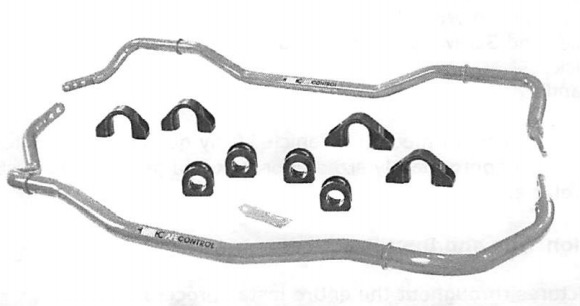
aFe Control Sway Bars
Part Numbers:
440-301001-N, 440-301001FN, 440-301001RN
Applications:
2015 Ford Mustang GT, Ecoboost
Reason: This installation requires minimal removal of major components other than those being replaced.
This procedure is best performed on a vehicle lift by qualified mechanics. If a lift is not available, use an appropriately sized floor jack and jack stands to support the weight of the vehicle.
Pre-Installation Tips and Best Practices:
• Take pictures throughout the entire install process
• Regular nut and bolt checks are crucial in maintaining safe vehicle operation, especially in racing applications.
• Re-torque end link bolts and sway bar brackets after every racing/track event. Also re-torque during regularly scheduled maintenance if installed on a frequently driven street vehicle.
• Mark bolts that have been torqued to spec with a paint pen so fasteners that have been torqued can quickly be identified.
• Thread locking compound is highly recommended on any stressed suspension components.
• The supplied grease can be cleaned from non-porous surfaces using a rag or cloth dampened with a spray of WD-40®. Keep in mind that WD-40® is solvent based and can potentially damage some paints and finishes.
Front OEM Sway Bar Removal
1. Use a multi-post lift or floor jack to lift the vehicle via the proper jacking points to a comfortable working height.
2. Using a 19mm socket remove the front wheels.
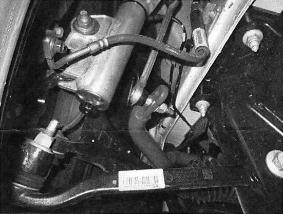
3. Unbolt the sway bar end links from the OEM sway bar using an 18mm wrench and 6mm Allen key.
4. Using an 18mm socket, remove the four bolts that attach the sway bar bushing brackets to the chassis.
5. Turn the steering wheel all the way clockwise as if making a right hand turn (this can also usually be accomplished by grabbing the sides of the rotor with both hands while simultaneously pushing with one arm and pulling with the other, depending on which side of the car you are on).
6. Take note of the orientation of the stock bar and remove by pulling through the passenger side wheel well.
Front aFe Control Sway Bar Installation
7. Install the new aFe Control sway bar in the reverse order that the OEM bar was removed by pushing the bar through the passenger side wheel well. Ecoboost equipped models have more room to move the bar within the engine bay than GT, but turbo/radiator hoses may need to be pushed aside.
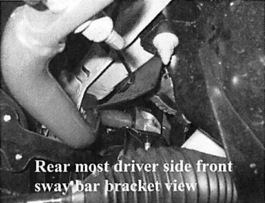
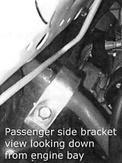
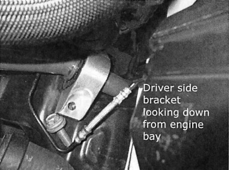
8. Apply a generous amount of supplied grease on the bushing and install on the bar. Install the CNC machined aluminum bushing bracket using the OEM bolts and an 18mm socket. Multiple extensions will be necessary on the passenger side. The bolts closest to the front of the vehicle can be accessed from the engine bay between the radiator and front of the engine. The rear bracket bolts are most easily accessible from inside the fender well with the wheel off. On GT models, the alternator makes the use a ratchet and socket difficult on the rear of the driver side bracket so it is recommended to use a ratcheting box end wrench. Ecoboost models do not have this clearance issue.
9. Using a floor jack, or a screw jack, apply lift either of the lower control arms until the end link can be attached to sway bar.
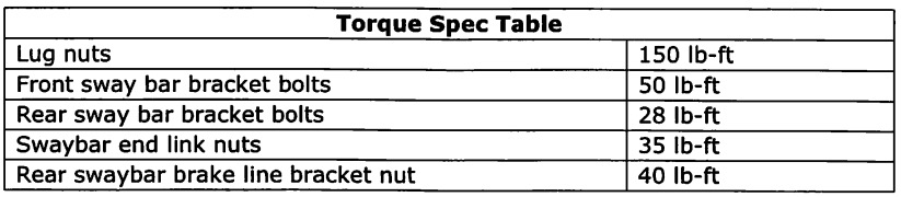
10. Reattach the sway bar end links to the sway bar using an 18mm wrench and 6mm Allen key. Torque nuts to 35 lb-ft.
11. Reinstall the front wheels using a 19mm socket and torque to 150 lb-ft
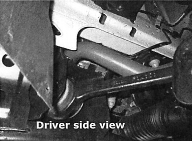
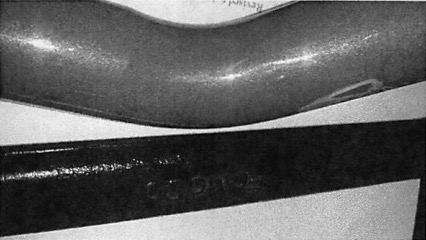
12. INSTALLER NOTE: When the aFe Control front sway bar has been installed, the lower trailing arm will appear as if it will come into contact with the sway bar as shown in the picture below. The amount of clearance will increase (bar will move away from the trailing arm) as the car is lowered back to standard or Lowered ride height.
Rear OEM Sway Bar Removal
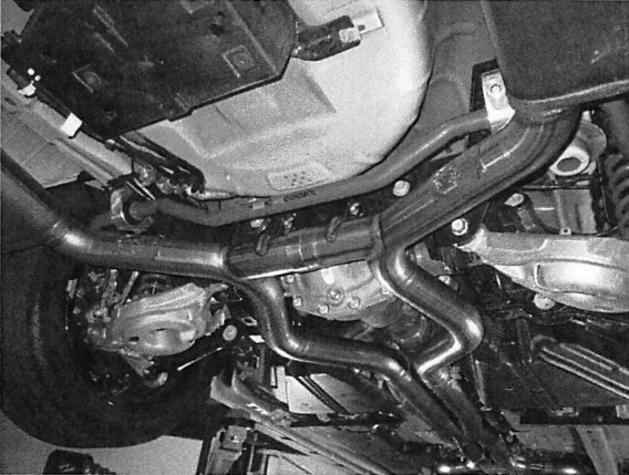
1. Using proper jacking points, lift and support the rear of the car on jack stands or use a lift.
2. The rear sway bar on the S550 Mustang can typically be installed without removing the wheels and most street exhaust systems.
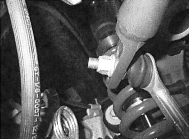
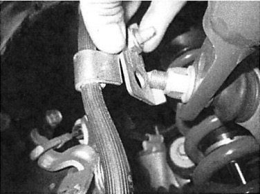
3. Use an 18mm socket or wrench and a 6mm hex key to loosen and remove the sway bar end links and brake line bracket from the sway bar.
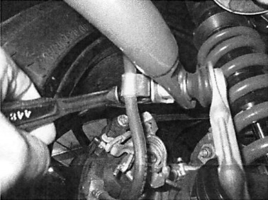
4. Use a 13mm socket or wrench to remove the four sway bar bracket bolts. It is recommended to leave bolts installed but loose until all four can be removed by hand at once with the sway bar to minimize the risk of the bar dropping.
Rear aFe Control Sway Bar Installation
1. Apply a generous amount of supplied grease onto the bushing before installing the bushing onto the bar.
2. Slide the machined aluminum brackets provided in the kit onto the bushings and move the bar into position.
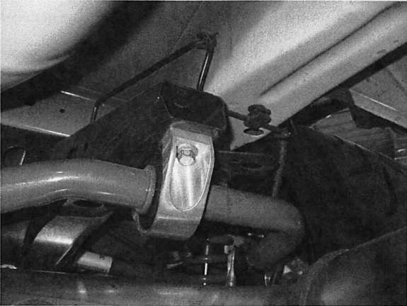
3. While supporting the bar in position, bolt the brackets into the mounting holes using the stock hardware. Start the threads by hand first until all four bolts have threads started and the bar is able to safely hang on its own. *Do not torque the bolts to spec at this time. The urethane compresses when the bracket is fully installed and makes bar more difficult to rotate. Leaving these bolts loose will allow for easier installation of the end links.
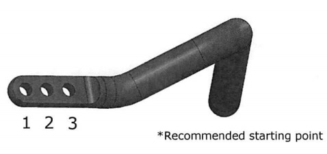
4. Push the end link studs into the holes corresponding to the desired stiffness. It is advisable to start at the intermediate setting first (refer to page 6). *It is not uncommon that the second end link is more difficult to install than the first.
5. Once both studs are in their respective positions, the four frame mounting bolts that were left loose in step 3 may now be fully torqued down to 28 lb-ft.
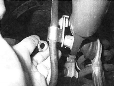
6. The kit includes a thin hex nut to secure the brake line bracket to the end of the end link stud. Use a 19mm wrench or socket and torque this nut to 40 lb-ft.
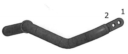
Front swaybar settings:
Hole I — Soft*
Hole 2 — Stiff
Rear swaybar settings: Hole 1 — Soft
Hole 2 — Intermediate* Hole 3 — Stiff