FREE 1 to 3-Day Delivery on Orders $149+ Details
How to Install AFE Control Featherlight Single Adjustable Coilover Kit (15-18 w/o MagneRide) on your Ford Mustang
Installation Time
4 hours
Tools Required
- 18mm box end wrench
- 23mm box end wrench
- 8mm socket
- 10mm socket
- 13mm socket
- 18mm socket
- 19mm socket
- 21mm socket
- 21mm deep socket
- 3/8"drive rachet
- 3/8" drive ratchet
- 6mm allen wrench
- 3/8" drive torque wrench
- Spring Compressor
- 2 post lift and Screw Jack (preferred)
- floor jack
- jack stands
- pry bar
Front Installation
1. Use a multi-post lift of floor jack to the lift vehicle via the proper jacking points to a comfortable working height.
2. Using a 19mm socket, remove the front wheels.
3 Unblot the sway bar end links from the OEM stru using an 18mm wrench and 8mm socket.
4 Using a 10mm socket, remove the clip holding the brake lines to the body.
5. Using a 23mm wrench, and a 21 socket and impact wrench remove the 2 bolts holding the strut housing to sppindleupright. Make sure you use a floor or screw jack to hold the spindel in place while removing the strut.
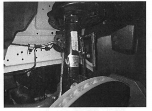
Note: On models equipped with the performance brake upgrade, it may be necessary to remove the brake caliper from the spindle in order to access the spindle nuts. Do not remove the brake lines, you can use a strao or safety wire to hold the caliper in place.
6. Using a 15mm socket, remove the 3 bolts holding the sprut mount into the vehicle. Remove the strut from the vehicle.
7. Using a proper string compressor, remove the strut center bolt with a 21mm deep socket.
8. Install the upper strut mount onto the coilover and torque the center nut to 40 lb-ft. Re-use the stock nut.
9. Install the coilover into the vehicle and torque the 3 upper mount bolts to 28 lb-ft.
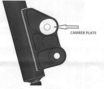
10. Select the correct Camber Plate for the uuper bolt and install it in the strut.
It is recommended to start with the plate with the centered hole. The offset plate can be installed for either more or less camber during alignment during alignment. This can also e used to gain the clearance.
11. Using a 23mm wrench, and a 21mm socket and an impact rench re attach the 2 bolts holding the strut housing to spindle upright. If brake calipers were removed during the installation, re-attach now.
12. Using a 10mm socket, re-attach the clip holding the brake lines to the body.
13. Re attach the sway bar end links to the strut using an 18mm wrench and 8mm socket. Torque nuts to 35 lb-ft.
14. Set the spring perch so that 1.5" of thread is showing under the perch to start.
15. Reinstall the front wheel using a 19mm socket and torque to 150 lb-ft.
16. Continue to other side, repeat steps 3-15.
Rear Installation
1. Using proper jacking points, lift and support the rear of the car on jack stands or use a lift.
2. Using a 19mm socket, remove the rear wheels.
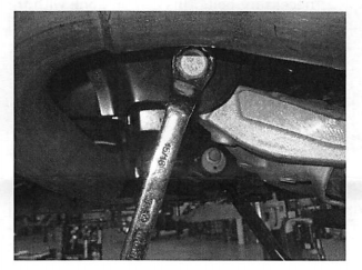
3. Remove the OE rear shock fromt the vehicle by unbolting the two large bolts holding the ujpper aluminum bracket to inner fender.
4. In the next step, you may need to raise the exhaust system to gain access to necessary bolt. This can be done with the use of a floor jack, or a screw jack.
5. Remove the exhaust hanger bolts and lift the exhaust enough to access the inner lower a-arm bolts.
6. Use an 18mm socket or wrench and a 6mm hex key to loosen and remove the sway bar end links where they attach to lower control arm.
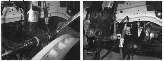
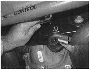
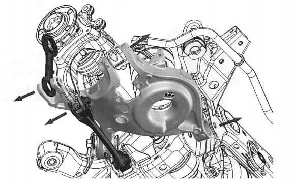
7. Using 18 & 21mm sockets, remove the spindle bolts as shown by red arrows. Support the spindle with a jack, and position the toe links out of the way.
8. Using a 23mm wrench, remove the inner low a-arm bolt. Make sure you are using a jack to secure the lower arm from falling.
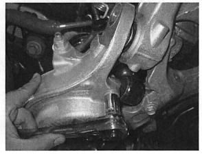
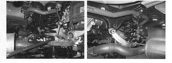
9. Use a pry bar to remove the spring from the lower cntrol arm.
10. Use a floor, or a screw jack to raise the lower a-arm back into place. Using a 23mm wrench, re-install the inner lower a-arm bolt. Torque to 60 lb-ft,
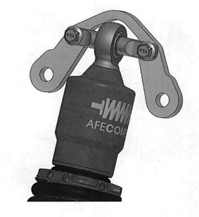
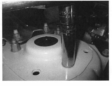
11. Install the rear coilvoer to the inner fender area with the supplied M12 x 30 bolts. Torque bolts to 40 lb-ft.
12. To set a starting point for ride height, set the spring perch .5" below the orange head.
13. Using 18 & 21mm sockets, reinstall the spindle bolts to the lower control arms. Torque bolts to 40 lb-ft.
14. Uing a 15mm socket and original hardware, attach the lower shock mount t-bar to the lower control arm. Orient the t-bar to maximize clearance between the spring and the drive axle.
15. Re-attach the sway bar end links to lower a-arm using an 18mm wrench and 6mm allen wrench. Torque nuts to 35 lb-ft.
16. Continue to other side, and repeat 4-16.
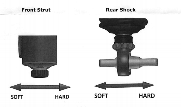
17. Set all 4 dampers to the recommended settings.
18. Reattach all the exhaust hangers and brackets as removed in Step 3.
19. Doubke check all your work, and make sure all bolts have been properly torqued and reinstalled.
20. Reinstall the rear wheels using a 19mm socket and torque to 150 lb-ft.
Recommended Damping Starting Points
Each shock has 24 clicks of adjustment. Setting are listed in number of clicks down from full stiff. To adjust turn until stiff and count clicks as you back off.