 FREE 1 to 3-Day Delivery on Orders $149+ Details
How to Install an Air Lift Performance 3H Height and Pressure Adjustable Air Suspension System
Shop Parts in this Guide
Introduction
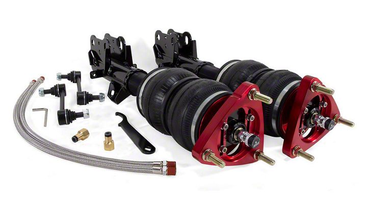
Air Lift Performance thanks you for purchasing the most complete, fully engineered highperformance air suspension made for the Ford Mustang S550. Read these installation instructions to correctly and safely set up the vehicle for a #lifeonair.
Air Lift assumes that the installer has the mechanical knowledge and ability to work on vehicle suspension systems and has basic tools necessary to complete the project. Special tools needed to complete the installation are noted on the Installation Diagram page.
Air Lift reserves the right to make changes and improvements to its products and publications at any time. For the latest version of this manual, contact Air Lift Performance at (800) 248-0892 or visit www.airliftperformance.com.
An Air Lift Performance air management system is highly recommended for this product. Learn more at air-lift.co/productlines.
NOTATION EXPLANATION
Hazard notations appear in various locations in this publication. Information which is highlighted by one of these notations must be observed to help minimize risk of personal injury or possible improper installation which may render the vehicle unsafe. Notes are used to help emphasize areas of procedural importance and provide helpful suggestions. The following definitions explain the use of these notations as they appear throughout this guide.
DANGER - INDICATES IMMEDIATE HAZARDS WHICH WILL RESULT IN SEVERE PERSONAL INJURY OR DEATH.
WARNING - INDICATES HAZARDS OR UNSAFE PRACTICES WHICH COULD RESULT IN SEVERE PERSONAL INJURY OR DEATH.
CAUTION - INDICATES HAZARDS OR UNSAFE PRACTICES WHICH COULD RESULT IN DAMAGE TO THE MACHINE OR MINOR PERSONAL INJURY.
NOTE - Indicates a procedure, practice or hint which is important to highlight
Important Safety Notices
WARNING - DO NOT INFLATE AIR SPRINGS WHILE OFF OF THE VEHICLE. DAMAGE TO ASSEMBLY MAY RESULT AND VOID WARRANTY.
CAUTION - DO NOT WELD TO OR MODIFY PERFORMANCE STRUTS/SHOCKS IN ANY WAY. DAMAGE TO UNIT MAY OCCUR AND WILL VOID WARRANTY.
Installation Diagram
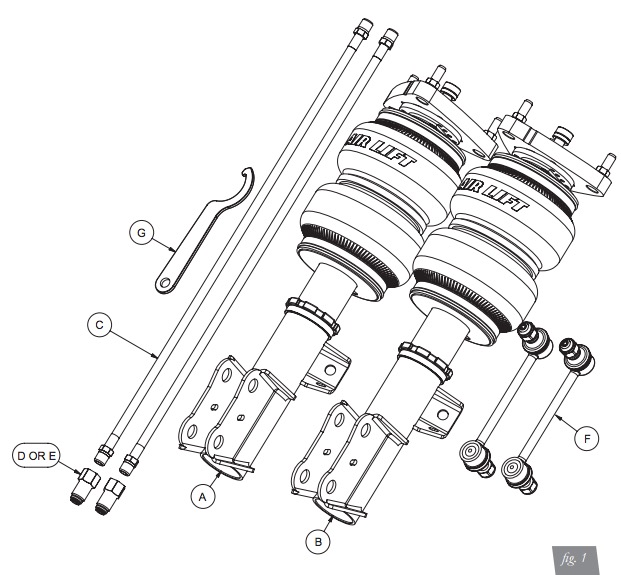
HARDWARE LIST
| Item | Part # | Description | Qty |
|---|---|---|---|
| A | 35308 | ASM, Strut, S550 Mustang Right Front | 1 |
| B | 35307 | ASM, Strut, S550 Mustang Left Front | 1 |
| C | 20997 | Leader Hose, 1/4” ID | 2 |
| D | 21810 | Union, 1/4”FNPT X 1/4” PTC, DOT | 2 |
| E | 21987 | Union, 1/4”FNPT X 3/8” PTC, DOT | 2 |
| F | End Link - 215mm | 2 | |
| G | Spanner Wrench | 1 |
Missing or damaged parts? Call Air Lift customer service at (800) 248-0892 for a replacement part
Installing the Air Suspension
PREPARING THE VEHICLE
1. Elevate and support the vehicle using its approved lifting points.
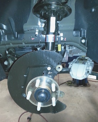
2. Remove the front wheel and support the hub assembly (Fig. 2).
Fig 2
REMOVAL OF STOCK SUSPENSION
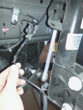
1. Unclip the sensor wire from the two attaching points on the strut (Figs. 3 and 4).
Fig 3
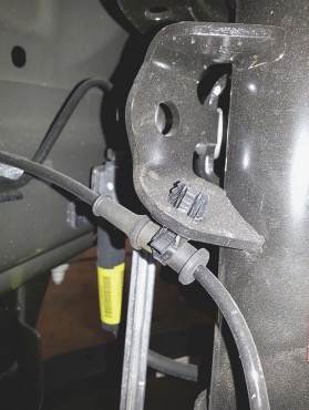
Fig 4
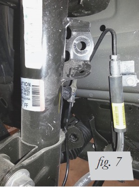
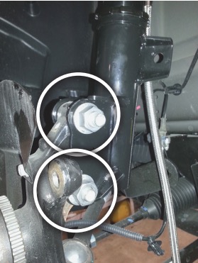
2. Unthread the stabilizer bar end link nuts from the strut and bar. Remove the end link (Figs. 5-7).
Fig 5
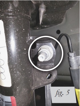
Fig 6
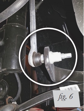
Fig 7
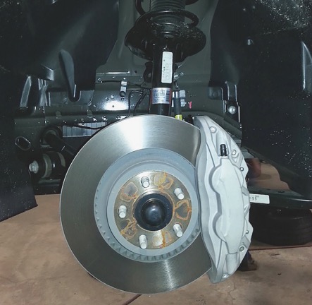
3. Unbolt the brake caliper. Remove the brake caliper and brake rotor. Secure the brake caliper out of the way while preventing strain on the brake line (Figs. 8 and 9).
NOTE: The lower strut attaching bolts have a splined section that bites into the knuckle. Because of this, the brake caliper and rotor will need to be removed in order to push the bolts out.
Fig 8
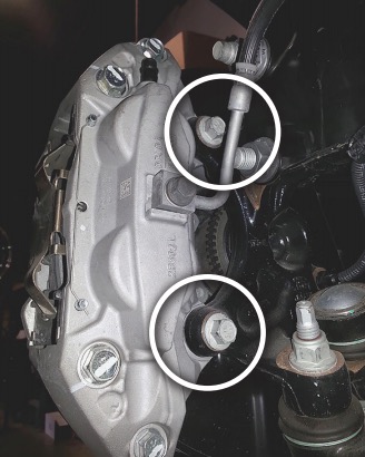
Fig 9
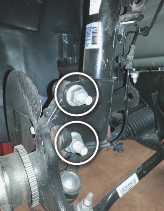
4. Remove the two lower strut nuts and use a hammer to remove the bolts, while taking care not to damage the threads (Fig. 10). Support the knuckle to prevent damage to the lower ball joint.
Fig 10
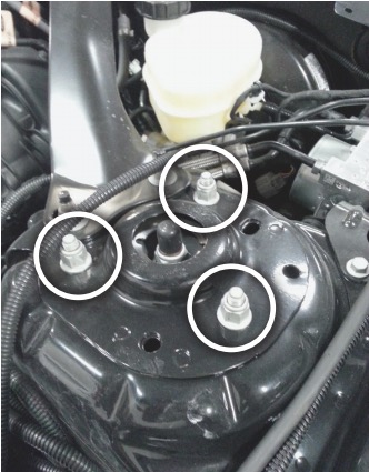
5. Within the engine compartment, unthread the three upper mount nuts and remove the strut from the vehicle (Fig. 11)
Fig 11
INSTALLING THE KIT COMPONENTS
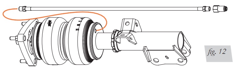
1. Begin by installing the leader hose into the air spring. Apply thread sealant to the threads of the leader hose. Tighten the appropriate fitting to the air line (1 3/4 turns beyond handtight). Tighten the leader hose into the air spring 1 3/4 turns beyond hand-tight (Fig. 12).
Fig 12
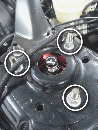
2. Attach the camber plate to the strut tower and torque nuts to 41 Nm (30 lb.-ft.) (Fig. 13).
3. Reinstall the lower mount bolts through the knuckle with the bolt heads toward the front of the vehicle (Figs. 14 and 15). A hammer may be required to push the bolts through the knuckle. Torque to 250 Nm (184 lb.-ft.).
Fig 13
4. Reinstall the brake rotor and brake caliper. Torque fixed brake caliper bolts to 115 Nm (85 lb.-ft.). For sliding calipers (not shown), torque the guide pin bolts to 33 Nm (24 lb.-ft.) (Figs. 16 and 17).
Fig 14
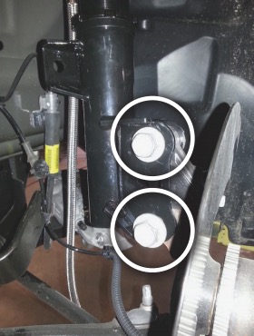
Fig 15
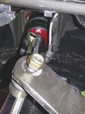
5. Install the new stabilizer end link. Torque nuts to 103 Nm (76 lb.-ft.) (Figs. 18 and 19).
Fig 16
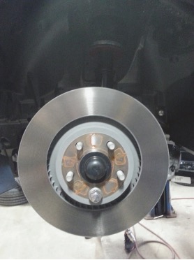
Fig 17
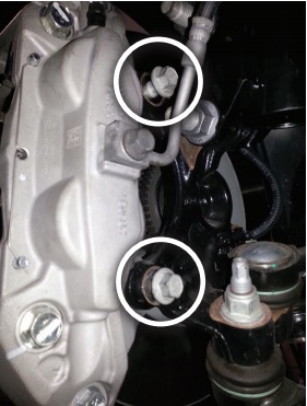
Fig 18
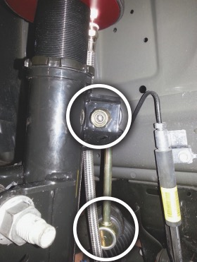
Fig 19
ROUTING THE AIR LINES
1. Fully compress the suspension using a jack. With the suspension compressed, review the best routing for the leader hose that is clear of all suspension and steering components.
2. Routing should allow for the suspension to extend and steer without kinking, pulling the line tight or rubbing on other components. Following the brake line routing is often a good place to start. Check clearances to all other components.
Before Operating
SETTING THE RIDE HEIGHT
1. With the suspension fully compressed, take a measurement from the fender to a chosen reference point – typically the center of the axle. Record this measurement as max compression (MC).
2. Cycle the suspension to max extension (ME) and record the measurement from the fender to the same reference point.
3. Add ME and MC, then divide the total by 2. Set the suspension to this point. This position will give 50% stroke in either direction and is a starting point for ride height (fig. 20).
Fig 20

4. With the suspension at this position, loosen, then re-torque all suspension bushing pivot joint fasteners to the manufacturer’s specifications (Table 1):
Table 1
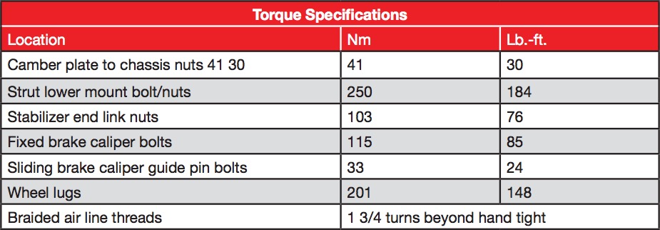
Table 2
CHECK FOR BINDING
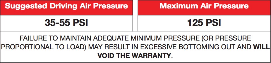
1. Inflate and deflate the system (do not exceed 125 PSI) to check for clearance or binding issues. With the air springs deflated, check clearances on everything so as not to pinch brake lines, vent tubes, etc. Clear lines if necessary.
2. Inflate the air springs to 75-90 PSI and check all connections for leaks.
CAUTION - MAKE SURE THE FRONT WHEELS ARE STRAIGHT WHEN DEFLATING AND REINFLATING AIR BAGS.
DAMPING ADJUSTMENT
Suspension damping is a matter of compromise. Setting it too stiff will make the ride feel jarring. In addition, if the suspension is too stiff, the tires will lose contact with the road, reducing control and power delivery. On the other hand, if the suspension is too soft, the car can experience brake dive and excessive bouncing. The sweet spot lies somewhere in the middle. Air Lift dampers have a range of adjustment, which allows the driver to tune the ride and handling to his or her preferences.
Air Lift recommends damper and air pressure settings for every vehicle kit, but it is impossible to consider every situation. For example, even though Air Lift kits replace the dampers and springs, vehicles with sport-tuned suspensions might have stiffer bushings, larger anti-roll bars, bigger wheels, wider tires, etc. These settings may need to be adjusted to different vehicles and driving characteristics.
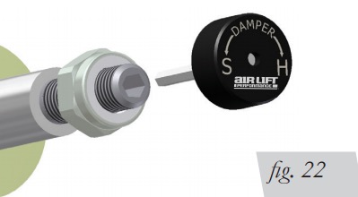
1. The dampers in this kit have 30 settings, or “clicks,” of adjustable compression and rebound damping characteristics. Damping is changed through the damper rod using the supplied adjuster (Figs. 21 & 22) or an 3mm hex key (not included).
2. Turn the adjuster clockwise (H) and the damping settings are hardened, reducing oscillations and body motion. Turn the adjuster counterclockwise (S) and the damping is softened.
3. Each damper in this kit is preset to “-17 clicks.” This means that the damper is adjusted 17 clicks away from full stiff, which starts at 0. Counting up from full stiff is the preferred method of keeping track of, or setting, damping. This setting was developed on a 2015 Ford Mustang 2.3L EcoBoost.
Fig 21
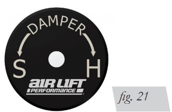
Fig 22
ALIGNING THE VEHICLE
1. Set the vehicle to the height at which it will most often be driven.
2. If the ride height is lower than stock, Air Lift recommends loosening all pivot points (bolts, nuts) on any control arm, strut arm or radius rod that contains bushings. Once they have been loosened, re-torque to stock specifications (Table 1).
NOTE - It may be necessary to cycle the suspension to loosen the bushing from its mount. This will help re-orient the bushing at its new position based on the chosen ride height.
3. Get a shop alignment of the vehicle at the new chosen ride height.
ADJUSTING EXTENDED OR DROP HEIGHT USING LOWER MOUNT
These dampers have been pre-set at the factory to provide maximum drop height while maintaining adequate tire clearance to the air spring. If you wish to gain more extended height (lift), which is the same as reducing drop height, or want to lower the chassis further and there is still adjustment available at the lower mount, please use the following procedure:
1. Support the vehicle with jack stands or a hoist at approved lifting points.
2. Remove the wheel.
3. Using the supplied spanner wrench, loosen the locking collar (Fig. 23).
Fig 23
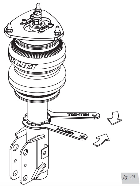
The dampers in this kit may look different, but they all allow adjustment of the locking collar with the included spanner wrench.
4. Deflate the air spring to 0 PSI on the corner you are adjusting.
5. Disconnect lower mount from suspension.
6. Spin the lower mount to the desired location.
NOTE - Not all vehicles will have further drop height available.
7. Re-install lower mount to suspension and torque fasteners.
8. Tighten the lower locking collar to the lower mount using significant force
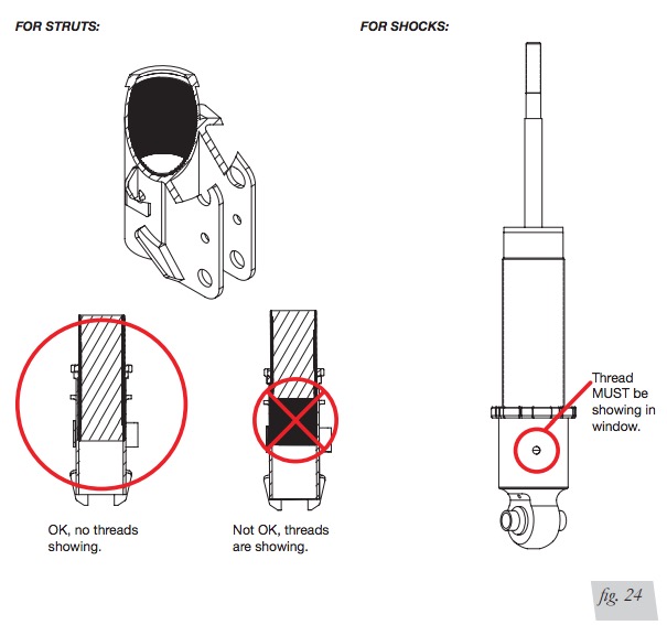
CAUTION - WHEN ADJUSTING HEIGHT UPWARD, MAKE SURE THAT THE DAMPER BODY ENGAGES ALL THE THREADS OF THE LOWER MOUNT (FIG. 24). WHEN ADJUSTING DOWNWARD, MAKE SURE THERE IS ADEQUATE AIR SPRING CLEARANCE TO THE TIRE/WHEEL ASSEMBLY. CLEARANCE MUST BE CHECKED WITH SYSTEM FULLY DEFLATED AS WELL AS FULLY INFLATED TO ENSURE THAT NO RUBBING OCCURS. FAILURE TO MAINTAIN ADEQUATE CLEARANCE CAN RESULT IN AIR SPRING FAILURE AND WILL NOT BE COVERED UNDER WARRANTY.
CAUTION - DO NOT ADJUST HEIGHT BY SPINNING AIR SPRING ON DAMPER! DOING SO MAY CAUSE AN AIR LEAK AND COMPROMISE THE ASSEMBLY.
Fig 24
INSTALLATION CHECKLIST
Clearance — Inflate the air springs to 75-90 PSI and make sure there is at least 1/2” clearance from anything that might rub against the air spring. This should be checked with the air spring fully inflated and fully deflated.
Leak — Inflate the air springs to 75-90 PSI and check all connections for leaks. All leaks must be eliminated before the vehicle is road tested.
Heat — Be sure there is sufficient clearance from heat sources, at least 6” for air springs and air lines. If a heat shield was included in the kit, install it. If there is no heat shield, but one is required, call Air Lift customer service at (800) 248-0892.
Fastener — Recheck all bolts for proper torque.
Road — Inflate the springs to recommended driving pressures. Drive the vehicle 10 miles and recheck for clearance, loose fasteners and air leaks.
Operating instructions — If professionally installed, the installer should review the operating instructions with the owner. Be sure to provide the owner with all paperwork that came with the kit.
POST-INSTALLATION CHECKLIST
Overnight leak down test — Recheck air pressure 24 hours after installation and driving of the vehicle. If the pressure has dropped more than 5 PSI, there is a leak that must be fixed.
Air pressure requirements — It is important to understand the air pressure requirements of the air spring system. Regardless of load, the air pressure should always be adjusted to maintain adequate ride height at all times while driving.
Thirty-day or 500-mile test —Recheck the air spring system after 30 days or 500 miles, whichever comes first. If any part shows signs of rubbing or abrasion, the source should be identified and moved, if possible. If it is not possible to relocate the cause of the abrasion, the air spring may need to be remounted. If professionally installed, the installer should be consulted. Check all fasteners for tightness.
Use, Maintenance and Servicing
1. An Air Lift air management system is strongly recommended for this product, but it is possible to operate without one. The air lines can be routed to Schrader valves for use with a separate air compressor. Air lines and Schrader valves are not included with Air Lift Performance kits and would need to be purchased separately. To learn more about Air Lift management systems visit air-lift.co/productlines.
2. Check the air pressure before driving.
WARNING - BEFORE SERVICING THE VEHICLE, MAKE SURE TO TURN OFF “RISE ON START” AND “PRESET MAINTAIN.” THIS WILL ELIMINATE ANY UNINTENDED SUSPENSION CYCLING IF YOU NEED TO TURN THE KEY ON IN THE VEHICLE FOR ANY REASON.
TUNING THE AIR PRESSURE.
Pressure determination comes down to three things — level vehicle, ride comfort and stability.
1. Level vehicle
Depending on load, it is possible one side will need more pressure than the other to level the vehicle.
2. Ride comfort
If the vehicle has a harsh ride, it may be due to either too much pressure or not enough causing frequent bottoming. Also, riding the vehicle at the top, or close to the top of the available stroke will cause an uncomfortable ride due to a lack of rebound travel. This situation should be avoided for driving any significant distance. Try different pressures to determine the best ride comfort. See the Air Lift suggested driving air pressure for this vehicle (Table 2).
3. Stability
Stability translates into safety and should be the priority, meaning the driver may need to sacrifice a perfectly level and comfortable ride. Stability issues include roll control, bounce, dive during braking and sponginess. Tuning out these problems usually requires additional air pressure, damping or both.
Troubleshooting Guide
TIPS FOR INSTALLING AIR LINES
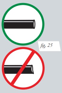
When cutting air lines, use a sharp knife or a hose cutter and make clean, square cuts (Fig. 25). Do not use scissors or wire cutters because these tools will deform the air line, causing it to leak around fittings. Do not cut the lines at an angle.
Do not bend the 1/4” hose at a radius of less than 1” and do not put side load pressure on fitting. The hose should be straight beyond the fitting for 1” before bending.
Inspect hose for scratches that run lengthwise on hose prior to installation. Contact Air Lift customer service at (800) 248-0892 if the air line is damaged.
To watch a video demonstrating proper air line cutting, go to air-lift.co/cuttingairline
Fig 25
CHECKING FOR LEAKS
1. Inflate the air spring to at least 80 PSI.
2. Spray all connections with a solution of 1/5 liquid dish soap and 4/5 water. Spot leaks easily by looking for bubbles in the soapy water.
3. Check the air pressure again after 24 hours. A 2-4 PSI loss after initial installation is normal. Retest for leaks if the loss is more than 5 PSI.
FIXING LEAKS
1. Air line to PTC fitting: Try pushing the air line firmly into the fitting to ensure it is properly seated. If leak persists, deflate the spring and remove the air line by pushing the collar toward the fitting body and pulling firmly on the air line. Trim 1” off the end of the air line making sure the cut is clean and square. Reinsert air line firmly into fitting and pull back on the air line to make sure it is seated.
2. Threaded connection: If possible, tighten the fitting another half turn. If the leak persists, deflate spring, remove fitting and re-coat threads with thread sealant. Reinstall to hand tight and then use wrench to finish tightening an additional 1 3/4 turns.
3. Air spring O-ring seal: If a leak is found at the upper or lower air spring seal on a strut or shock, contact Air Lift customer service at (800) 248-0892.
Limited Warranty and Return Policy
WHAT THIS WARRANTY COVERS
Air Lift Company warrants to the original purchaser for a period of one year from the date of original purchase that the Air Lift Performance damper kits will be free from defects in workmanship and materials for the normal expected life of the part when used on cars and trucks as specified by Air Lift Company and under normal operating conditions, subject to the requirements and exclusions set forth below.
WHAT THIS WARRANTY DOES NOT COVER
The warranty does not apply to products that have been improperly applied, improperly installed, or which have not been maintained in accordance with installation instructions furnished with all products. This warranty does not apply and is void if damage or failure is caused by: accident, abuse, misuse (including but not limited to racing or off-road activities or commercial use), abnormal use, faulty installation, liquid contact, fire, earthquake or other external cause; operating the product outside Air Lift Company’s instructions, specifications or guidelines; or service, alteration, maintenance or repairs performed by anyone other than Air Lift Company to the product from its purchased condition. This warranty also does not apply to: Universal Air (Fabricator Kits), consumable parts, such as batteries; cosmetic damage, including but not limited to scratches or dents; defects caused by normal wear and tear or otherwise due to the normal aging of the product, or if any serial or identification number has been removed or defaced from the product. Air Lift Company reserves the right to change the design of any product without assuming any obligation to modify any product previously manufactured.
LIMITATION OF LIABILITY
To the extent permitted by law, this warranty and the remedies set forth herein are exclusive and in lieu of all other warranties, remedies and conditions, whether oral, written, statutory, express or implied. AIR LIFT COMPANY DISCLAIMS ALL STATUTORY AND IMPLIED WARRANTIES, INCLUDING WITHOUT LIMITATION, WARRANTIES OF MERCHANTABILITY AND FITNESS FOR A PARTICULAR PURPOSE AND WARRANTIES AGAINST HIDDEN OR LATENT DEFECTS TO THE EXTENT PERMITTED BY LAW.
To the extent such warranties cannot be disclaimed, such implied warranties shall apply only for the warranty period specified above. Please note that some states do not allow limitation on how long an implied warranty (or condition) lasts. So the above limitation may not apply to you.
Except as provided in this warranty and to the extent permitted by law, Air Lift Company shall not be liable for any direct, special, incidental or consequential damages resulting from any breach of warranty or condition, or arising in connection with the sale, use or repair of air lift products, or under any other legal theory, including but not limited to loss of use, loss of revenue, loss of actual or anticipated profits, loss of the use of money, loss of business, loss of opportunity, loss of goodwill, and loss of reputation. Air Lift Company’s maximum liability shall not in any case exceed the purchase price paid by you for the Air Lift product.
Please note that some states do not allow the exclusion or limitation of incidental or consequential damages, so the above limitation or exclusion may not apply to you.
HOW TO GET SERVICE
If a defect in workmanship or materials causes your Air Lift Performance product to become inoperable within the warranty period, before returning any defective product, call Air Lift Company at (800) 248-0892 in the U.S. and Canada (elsewhere, (517) 322-2144) to obtain a Returned Materials Authorization (RMA) number. The consumer shall be responsible for removing (labor charges) the defective product from the vehicle and returning it, shipping costs prepaid, to Air Lift Company for verification. Returns to Air Lift Company must be postage prepaid and sent to: Air Lift Company • 2727 Snow Road • Lansing, MI • 48917. You must prove to the satisfaction of Air Lift Company the date of original purchase of your Air Lift Performance product. You must also enclose the RMA number and a return address. A minimum $10 shipping and handling charge will apply to all warranty claims. You must also pack the product to minimize the risk of it being damaged in transit. If we receive a product in damaged condition as the result of shipping, we will notify you and you must seek a claim with the shipper.
WHAT AIR LIFT COMPANY WILL DO
If you submit a valid claim to Air Lift Company during the warranty period, Air Lift Company will, at its option, repair your Air Lift Performance product or furnish you with a new or rebuilt product. Air Lift Company will not reimburse you for repairs or replacement parts provided by other parties. Your repaired or replacement Air Lift Performance product will be returned to you (subject to payment of the required warranty claim shipping and handling charge) and it will be covered under the warranty for the balance of the warranty period, if any. When a product or part is replaced, any replacement item becomes your property and the replaced item becomes property of Air Lift Company. You are responsible for installation/reinstallation (labor charges) of the product.
HOW THE LAW RELATES TO THIS WARRANTY
This warranty gives you specific legal rights and you may also have other rights which vary from state to state. By this warranty, Air Lift Company does not limit or exclude your rights except as allowed by law. To fully understand your rights, you should consult the laws of your state.
Replacement Part Information
If replacement parts are needed, contact the local dealer or call Air Lift customer service at (800) 248-0892. Most parts are immediately available and can be shipped the same day.
Contact Air Lift Company customer service at (800) 248-0892 first if:
• Parts are missing from the kit.
• Need technical assistance on installation or operation.
• Broken or defective parts in the kit.
• Wrong parts in the kit.
• Have a warranty claim or question.
Contact the retailer where the kit was purchased:
• If it is necessary to return or exchange the kit for any reason.
• If there is a problem with shipping if shipped from the retailer.
• If there is a problem with the price.
Contact Information
Mailing address
P.O. Box 80167
Lansing, MI 48908-0167
Shipping address for returns
2727 Snow Road
Lansing, MI 48917
Phone
Toll free: (800) 248-0892
International: (517) 322-2144
Email
[email protected]
Web address
www.airliftcompany.com
Need Help?
Contact Air Lift Company customer service department by calling (800) 248-0892. For calls from outside the USA or Canada, dial (517) 322-2144.
