 FREE 1 to 3-Day Delivery on Orders $149+ Details
How to Install JLT Performance Series 3 Cold Air Intake - Hydro Carbon (05-09 GT) on your Ford Mustang
Installation Time
1 hours
Tools Required
- Phillips and flat head screw driver or 5/16 nut driver
Thank you for purchasing our product. We hope you are satisfied with the look and performance. Take your time and it will be a smooth install. If you have any questions, contact us direct before going to the internet.
ATTENTION: A tune specific for this intake is required when installing this kit. Failure to add a tune specific for the JLT intake may result in major engine damage.
***DO NOT INSTALL KIT AND DRIVE WITHOUT A TUNE! ***
Please review complete instructions prior to installing.
1. Verify you have all of the following parts included in the kit: (1) JLT Plastic tube with PCV fitting, (1) Silicone Coupler 4.5” ID x 2”, (1) 4.5x9” S&B Air Filter, (1) JLT Heat Shield, (1) PCV hose, (2) #72 Clamps, (2) MAF Screws, (1) MAF Gasket, (1) Bolt
2. Gather all of the following tools needed for the installation: 10mm socket, extension and ratchet, torx 20 driver, Phillips and flat head screw driver or 5/16 nut driver
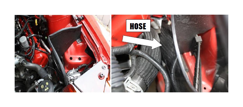
3. Unplug your MAF sensor plug and remove the stock intake by loosening the clamp at the throttle body and removing the 10mm bolt holding down the airbox. Unhook the PCV line at the valve cover and lift up and out.
4. Install JLT heat shield using the stock airbox bolt and replacing factory fan shroud bolt with supplied longer M6x1x25 bolt. ON SOME MODELS you will need to push in on coolant hose slightly to install shield as shown below :
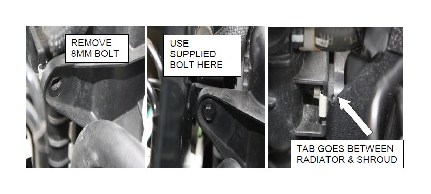
Remove factory 8mm bolt and use supplied 10mm Bolt to secure heat shield to radiator. Be sure heat shield mounting tab goes IN BETWEEN Radiator and fan should as shown below:
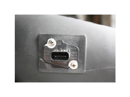
6. Remove the MAF sensor from the stock airbox using a torx T-20 driver and install in the JLT MAF housing using supplied Phillips head screws and gasket. Screws just need to be snug.
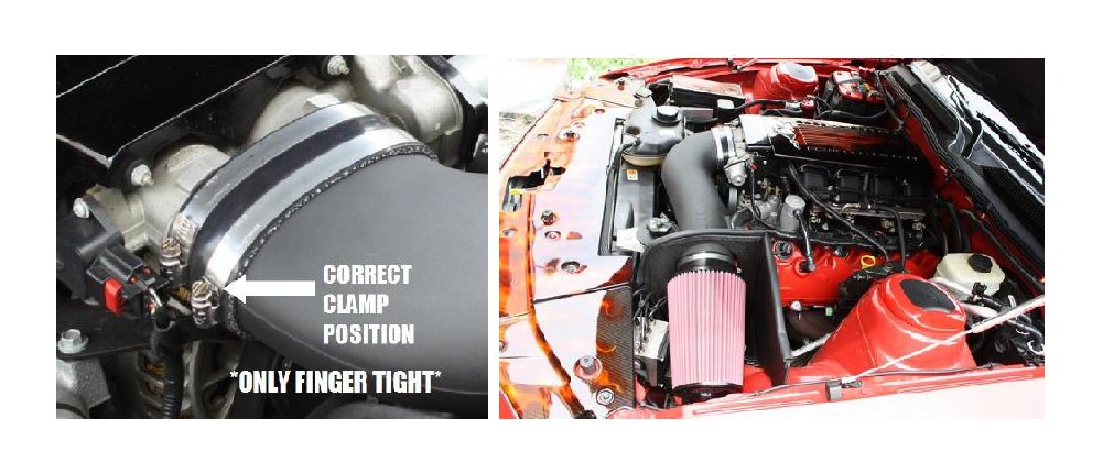
7. Install coupler and clamps on to JLT tube and install on to throttle body then install air filter on to JLT tube as shown:
** TIP ** Be sure to wipe any oil from the inside of air filter flange to avoid and slipping.
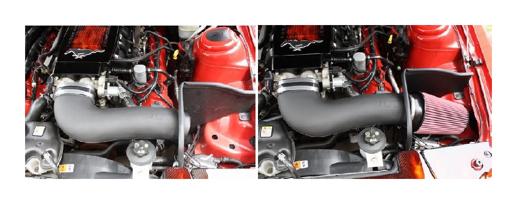
8. Plug in MAF sensor and supplied PCV hose and you’re DONE! Do not tighten clamps more then finger tight!!
This kit includes an S&B Powerstack pre-oiled reusable air filter. The frequency you should clean your filter will depend on your driving conditions. It is recommended to check your filter at every oil change or 3,000 miles. If there is a build up of dirt as thick as the wire mesh, then it’s time to clean your filter. As dirt builds up on your filter, the restriction of the airflow also increases. More frequent cleanings will improve your fuel economy and your vehicle’s performance.
To properly clean your filter, we recommend the S&B Precision Cleaning & Oiling Kit (located in the Parts Sold Separately Section of our website, www.JLTtruecoldair.com.
Thanks for the business. If you have any questions, please e-mail [email protected] or call 757-335-1940. Our hours are Monday-Friday. 8:00am – 5:00pm Eastern Time.
