 FREE 1 to 3-Day Delivery on Orders $149+ Details
How to Install Air Lift Performance 3P Pressure Adjustable Air Suspension System on your Mustang
HARDWARE LIST
| Item | Part # | Description | Qty |
|---|---|---|---|
| A | 35303 | ASM, Strut, Mustang SN95 Left Front | 1 |
| B | 35302 | ASM, Strut, Mustang SN95 Right Front | 1 |
| C | 20997 | Leader Hose, 1/4” ID | 2 |
| D | 21810 | Union, 1/4”FNPT X 1/4” PTC, DOT | 2 |
| E | 21987 | Union, 1/4”FNPT X 3/8” PTC, DOT | 2 |
| F | Spanner Wrench | 1 |
Installing the Air Suspension
PREPARING THE VEHICLE
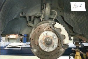
1. Elevate and support the vehicle from approved lifting points.
2. Remove the front wheels (fig. 2).
REMOVING THE STOCK SUSPENSION
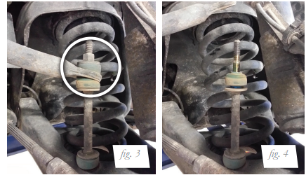
1. Unthread the stabilizer bar end link nuts from the bar (figs. 3 and 4).
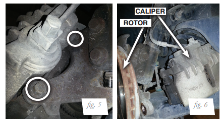
2. Unbolt and remove the brake caliper and rotor. Secure them out of the way taking care to prevent strain on the brake line (figs. 5 and 6).
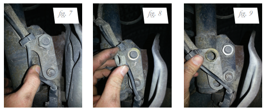
3. Remove the sensor wire and bracket from the lower strut mount (figs. 7-9).
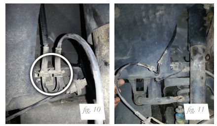
4. Unclip the sensor wire from the two attaching points within the fender housing and move the wire aside (figs.10 and 11).
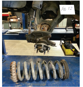
5. Remove coil spring (fig. 12).
THE COIL SPRING IS UNDER LOAD, USE FACTORY SERVICE INSTRUCTIONS TO REMOVE THE COIL SPRING
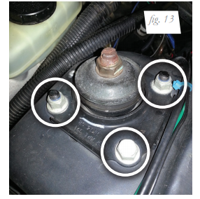
6. Remove the three upper bracket nuts and remove the strut (fig. 13).
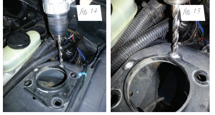
7. Remove the rivets holding the upper mount support bracket. Make certain the entire rivet has been removed (figs. 14 and 15).
AIR SUSPENSION INSTALLATION
1. Install the leader line into the air spring. Apply thread sealant to the threads of the leader hose. Tighten the appropriate fitting to the air line (one and three-quarter turns beyond hand-tight). Tighten the leader line into the air spring (one and three-quarter turns beyond hand-tight) (fig. 16).
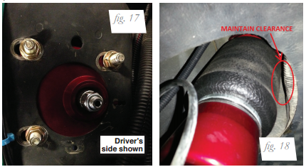
2. Attach the upper mount to the slotted strut tower (fig. 17), positioned completely inboard at limit of slots towards the engine. Re-install upper support bracket. Torque nuts to 34 Nm (25 ft-lbs). (Support bracket is not shown in figure 17 to show mount position in slots.)
DO NOT POSITION THE UPPER MOUNT OUTBOARD (AWAY FROM THE ENGINE). DRIVING VEHICLE WITH UPPER MOUNT POSITIONED OUTBOARD MAY CAUSE THE AIR SPRING TO CONTACT THE CHASSIS, WHICH COULD DAMAGE THE AIR SPRING
(FIG. 18).
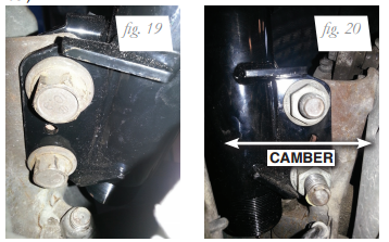
3. Align the lower mount holes with the knuckle and reinstall the bolts through the knuckle (fig. 19). Camber is adjusted with the slots in the lower mount (fig. 20). Torque to 190 Nm (141 ft-lbs.).
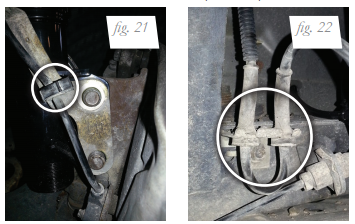
4. Reattach the sensor wire bracket and clip the wire to the fender housing (figs. 21 and 22). Torque the sensor bracket nut to 23 Nm (17 ft-lbs.).
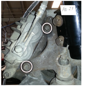
5. Reinstall the brake rotor and brake caliper (fig. 23). Torque the brake caliper bolts to 88 Nm (65 ft-lbs.).
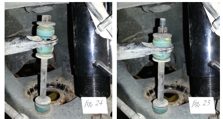
6. Reattach the stabilizer end link (figs. 24 and 25). Torque the nut to 16 Nm (11 ft-lbs.).
Formula for Calculating Ride Height
(ME MC)÷2=MID STROKE
See CAUTION on page 12 before proceeding.
7. Fully compress the suspension using a jack. With the suspension compressed, review the best routing for the leader hose that is clear of all suspension components. Routing should also allow for the suspension to extend and compress without kinking or pulling the line tight or rubbing on other components. Following the brake line routing is often a good place to start. Check clearances to all other components.
8. With the suspension fully compressed, take a measurement from the fender to some reference point – typically the center of the axle. Record this measurement as Max Compression.
9. Cycle the suspension to Max Extension and record the measurement from the same reference points.
10. Add ME and MC then divide by 2. Set the suspension to this point. This position will give 50% stroke in either direction and is a starting point for ride height (fig. 26).
Torque Specifications
| Location | Nm | ft-lbs. |
|---|---|---|
| Camber plate to chassis nuts | 34 | 25 |
| Strut lower mount bolt/nuts | 190 | 141 |
| Sensor wire bracket nut | 23 | 17 |
| Stabilizer end link nuts | 16 | 11 |
| Wheel lugs | 115 | 85 |
| Air fitting (use thread sealant) | 1-and-3/4 turns beyond hand-tight |
11. With the suspension at this position, loosen, then re-torque the lower control arm bolts to manufacturer’s specifications (Table 1).
DAMPING ADJUSTMENT
The dampers in this kit have 30 settings, or “clicks”, of adjustable compression and rebound damping characteristics. Damping is changed through the damper rod using the supplied adjuster (figs. 27 and 28) or a 3mm allen wrench.
Turn the adjuster clockwise and the damping settings are hardened. Turn the adjuster counterclockwise and the damping is softened.
Each strut is preset to “-15 clicks”. This means that the damper is adjusted 15 clicks away from full stiff. Counting down from full stiff is the preferred method of keeping track of, or setting, damping. This setting was developed on a 2002 Mustang GT and may need to be adjusted to different vehicles and driving characteristics.
ALIGNING THE VEHICLE
1. Using the control system, set the vehicle height to the new custom ride height.
2. If the custom ride height is lower than stock, we recommend loosening all pivot points (bolts, nuts) on any control arm, strut arm or radius rod that contains bushings. Once they have been loosened, re-torque to stock specifications.
ADJUSTING EXTENDED OR DROP HEIGHT
USING LOWER MOUNT
Your struts have been pre-set at the factory to provide maximum drop height while maintaining adequate tire clearance to the air spring. If you wish to gain more extended height (lift), which is the same as reducing drop height, or want to lower the chassis further and there is still adjustment available at the lower mount, please use the following procedure:
1. Support the vehicle with jack stands or a hoist at approved lifting points.
2. Remove the wheel.
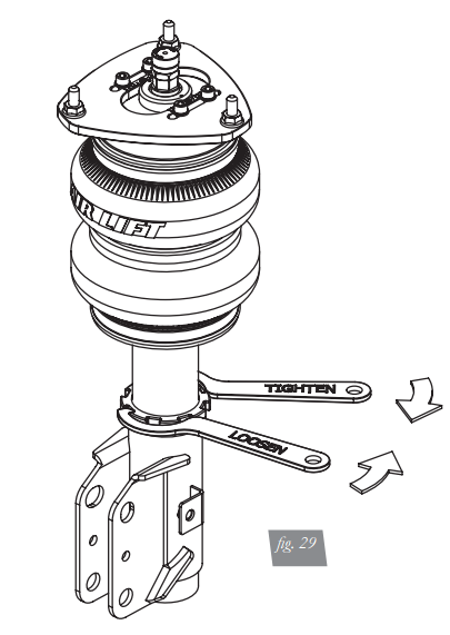
3. Using the supplied spanner wrench, loosen the lower locking collar (fig. 29).
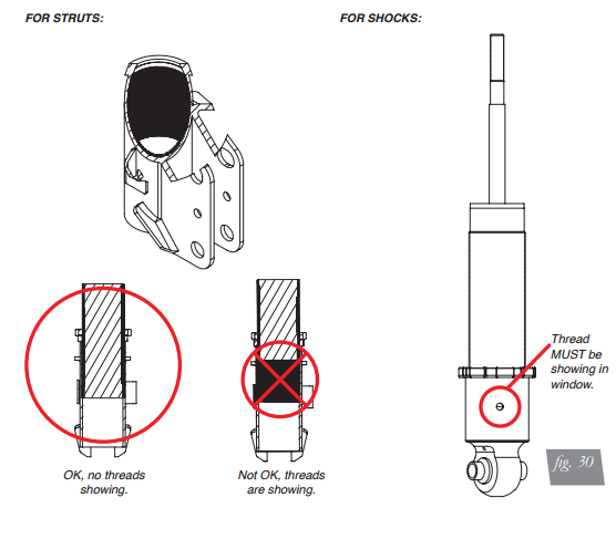
WHEN ADJUSTING HEIGHT UPWARDS, MAKE SURE THAT THE STRUT BODY ENGAGES ALL THE THREADS OF THE LOWER MOUNT (FIG. 30). WHEN ADJUSTING DOWNWARDS, MAKE SURE THERE IS ADEQUATE AIR SPRING CLEARANCE TO THE TIRE/WHEEL ASSEMBLY. CLEARANCE MUST BE CHECKED WITH SYSTEM FULLY DEFLATED AS WELL AS FULLY INFLATED TO ENSURE THAT NO RUBBING OCCURS.
FAILURE TO MAINTAIN ADEQUATE CLEARANCE CAN RESULT IN AIR SPRING FAILURE AND WILL NOT BE COVERED UNDER WARRANTY.
DO NOT ADJUST HEIGHT BY SPINNING AIR SPRING ON STRUT! DOING SO MAY CAUSE AN AIR LEAK AND COMPROMISE THE ASSEMBLY.
4. Deflate the air spring to 0 PSI on the corner you are adjusting.
5. Disconnect lower mount from suspension.
6. Spin the lower mount to the desired location.
Not all models will have further drop height available.
7. Re-install lower mount to suspension and torque fasteners.
8. Tighten the lower locking collar to the lower mount using significant force.
AFTER INITIAL INSTALLATION OF YOUR STRUTS/SHOCKS:
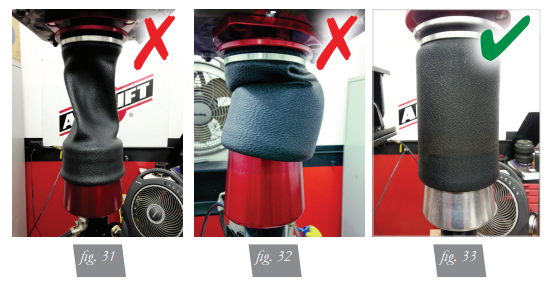
• DO NOT CYCLE THE SUSPENSION WITH THE AIR-LINE CONNECTED TO THE LEADER HOSE WITHOUT FIRST ADDING AIR SPRING PRESSURE. DOING SO MAY CAUSE THE AIR SPRING TO IMPROPERLY INFLATE (FIG. 31). IT IS SAFE TO CYCLE THE SUSPENSION TO CHECK FOR CLEARANCES ETC. WITH THE LEADER HOSE OPEN TO ATMOSPHERE (DISCONNECTED FROM AIR-LINE).
• BEFORE SETTING VEHICLE ON THE GROUND FOR THE FIRST TIME, IT IS VERY IMPORTANT TO INFLATE THE AIR SPRINGS TO AT LEAST 50 PSI. THIS WILL PREVENT ANY POSSIBILITY OF THE AIR SPRING KICKING OUT AND CAUSING A LEAK (FIG. 32).
Before Operating
MAKE SURE THE FRONT WHEELS ARE STRAIGHT WHEN DEFLATING AND
REINFLATING AIR BAGS.
1. Inflate and deflate the system (do not exceed 125 PSI) to check for clearance or binding issues. With the air springs deflated, check clearances on everything so as not to pinch brake lines, vent tubes, etc. Clear lines if necessary.
2. Inflate the air springs to 75-90 PSI and check all connections for leaks.
3. Air Lift part #27669 or #27671, AutoPilot V2 Air Management System, is highly recommended for this product.
4. Please familiarize yourself further with this product by reading the Product Use, Maintenance and Servicing section.
INSTALLATION CHECKLIST
Clearance test — Inflate the air springs to 75-90 PSI and make sure there is at least 1/2” clearance from anything that might rub against each sleeve. Be sure to check the tire, brake drum, frame, shock absorbers and brake cables.
- Leak test before road test — Inflate the air springs to 75-90 PSI and check all connections for leaks. All leaks must be eliminated before the vehicle is road tested.
- Heat test — Be sure there is sufficient clearance from heat sources, at least 6” for air springs and air lines. If a heat shield was included in the kit, install it. If there is no heat shield, but one is required, call Air Lift customer service at (800) 248-0892.
- Fastener test — Recheck all bolts for proper torque.
- Road test — The vehicle should be road tested after the preceding tests. Inflate the springs to recommended driving pressures. Drive the vehicle 10 miles and recheck for clearance, loose fasteners and air leaks.
- Operating instructions — If professionally installed, the installer should review the operating instructions with the owner. Be sure to provide the owner with all of the paperwork that came with the kit.
POST-INSTALLATION CHECKLIST
Overnight leak down test — Recheck air pressure after the vehicle has been used for
24 hours. If the pressure has dropped more than 5 PSI, then there is a leak that must
be fixed. Either fix the leak yourself or return to the installer for service.
- Air pressure requirements — Regardless of load, the air pressure should always be adjusted to maintain adequate ride height at all times while driving.
- Thirty day or 500 mile test — Recheck the air spring system after 30 days or 500 miles, whichever comes first. If any part shows signs of rubbing or abrasion, the source should be identified and moved, if possible. If it is not possible to relocate the cause of the abrasion, the air spring may need to be remounted. If professionally installed, the installer should be consulted. Check all fasteners for tightness.
