FREE 1 to 3-Day Delivery on Orders $149+ Details
How to Install Air Lift Performance 3P (1/4 in. Air Line, 4 Gallon 5-Port Lightweight Raw Aluminum T
Installing Air Lift Performance 3H/3P Kit
LAYOUT OVERVIEW
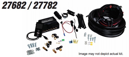
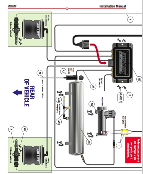
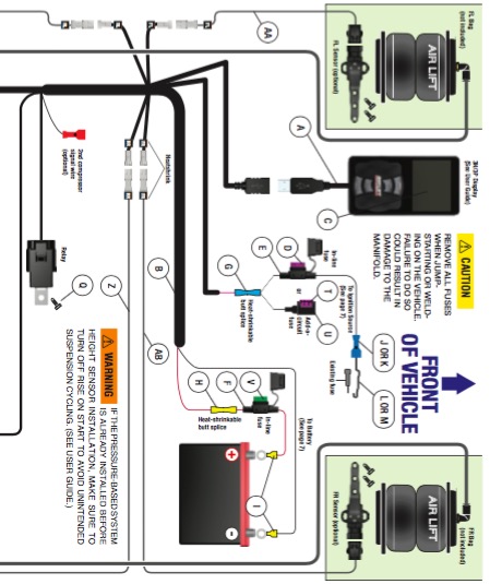
For a complete installation diagram, see pages 16-17. See page 2 for a complete parts list.
Layout
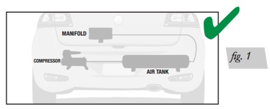
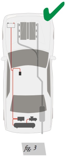
1. Plan component location first. Ideally, the manifold should be located at a level above the compressor and tank to avoid compressor ingested water from gathering in the manifold (fig. 1). This is most important for vehicles operated in below-freezing climates.
2. Prior to mounting components, check to make sure:
• the electrical harness connections will reach the manifold and compressor.
• the compressor leader hose will reach the tank.
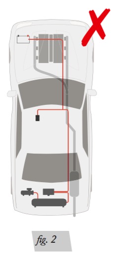
• the air lines will route cleanly through the vehicle without kinking or bending. Be sure to install all components as far as possible from any heat sources (figs. 2 and 3). Plan and prepare harness and air line routing thru the vehicle. Eliminate all sharp edges that could chafe. Use rubber grommets when passing through compartment walls.
TANK (OPTIONAL)
Tank pre-assembly
1. Determine tank location and orientation prior to installing fittings.
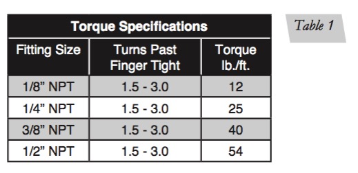
2. Before installing fittings, apply liquid pipe sealant or Teflon tape (not supplied) around the male threads, leaving the first two threads uncovered. NEVER BACK OFF AN INSTALLED PIPE FITTING TO ACHIEVE PROPER ALIGNMENT. LOOSENING INSTALLED PIPE FITTINGS WILL CORRUPT THE SEAL AND CONTRIBUTE TO LEAKAGE AND FAILURE.
3. Install the drain/fill PTC fitting in the tank’s lowermost threaded port.
4. Choose a middle tank threaded port for manifold/filter air line.
Tank install
1. Using the tank’s feet as a template, drill holes for hardware assembly.
2. Secure the tank using the supplied hardware.
3. Route the drain/fill air line with the Schrader valve (included in the tank hardware pack) preferably outside the vehicle (fig. 4).
4. Install tee fitting and pressure-relief valve in-line to the drain fill line. Locate the pressurerelief valve inside the vehicle, if possible.
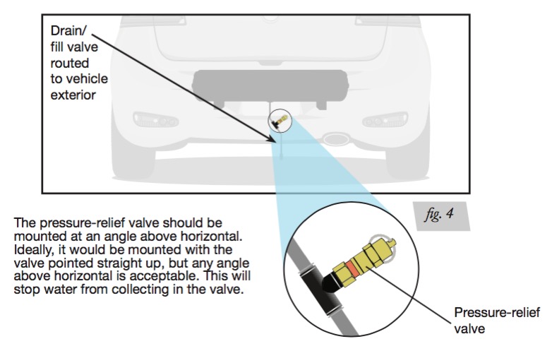
INSTALLATION OF THE PRESSURE-RELIEF VALVE IS IMPORTANT TO ENSURE THE SYSTEM IS NOT OVER-PRESSURIZED AS A RESULT OF A COMPRESSOR OR RELAY FAILURE.
FILTER
AIR COMPRESSORS TAKE IN MOISTURE (HUMIDITY) FROM THE OUTSIDE AIR SOURCE, AND WILL DEPOSIT THAT MOISTURE IN THE AIR TANK. THE AIR LIFT PERFORMANCE 3H/3P SYSTEM INCLUDES A FILTER THAT WILL GREATLY REDUCE THE POTENTIAL FOR MOISTURE TO ENTER THE MANIFOLD. HOWEVER, TANKS MUST BE REGULARLY PURGED TO ELIMINATE THE POSSIBILITY OF WATER ENTERING THE MANIFOLD. BE SURE TO PROVIDE EASY ACCESS TO DRAIN/FILL VALVE (PREFERABLY OUTSIDE THE VEHICLE). IF USING AN ENGINE-DRIVEN COMPRESSOR, AN ADDITIONAL COALESCING FILTER MUST BE USED. OTHERWISE THE LIFE OF THE PROVIDED FILTER MAY BE REDUCED DUE TO THE INCREASED POTENTIAL FOR OIL BEING INTRODUCED INTO THE SYSTEM.
1. Mount the filter to the tank using the appropriate fittings (fig. 5).
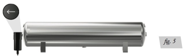
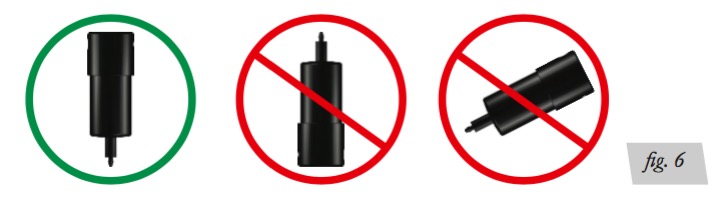
2. Ensure the filter is mounted in a vertical position. Do not install filter inverted or angled. (fig. 6).
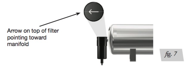
3. The arrow on the filter indicates flow direction and must point toward the manifold (fig. 7).
4. If choosing not to mount the filter to the tank, run necessary hose from tank to the filter and filter to the manifold using the appropriate fittings.
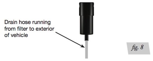
5. Run the hose from bottom of filter to location where water will drain (fig. 8).
INSTALL HARNESS
The harness can be routed inside or underneath the vehicle. In either case, ensure all parts of the harness are protected from abrasive edges and heat sources. DISCONNECT THE BATTERY GROUND BEFORE INSTALLING THE SYSTEM. REMOVE ALL FUSES WHEN JUMP-STARTING OR WELDING ON THE VEHICLE. FAILURE TO DO SO COULD DAMAGE THE MANIFOLD.
1. Manifold/relay/compressor connections
• Attach the manifold connector; it will “click” into place once fully seated.
• Mount the compressor relay using supplied hardware.
• Cut off the spade and eyelet from the compressor power (red) and ground (black) wires.
• Attach the compressor (red) wire to the main harness compressor power (red/white) wire using the supplied heat-shrinkable butt splice.
• Attach the compressor (black) wire to the main harness compressor ground (black) wire using the supplied heat-shrinkable butt splice. 2. Battery/ignition connections
• Route battery power (red) and ground (black) wires of the main harness to the battery.
• Attach the battery power (red) wire to the red wire of the fuse holder using supplied heat shrinkable butt splice.
• Attach supplied ring terminal to the other end of the fuse holder and fasten to the positive battery ( ) terminal or stud.
• Install a 30A fuse into this fuse holder and close the cap.
• Attach the other ring terminal to the ground (black) wire and fasten to the negative battery (-) terminal or stud.
• Route the ignition (pink) wire to a key-switched ignition source that remains on during cranking. Examples include: ECU, fuel pump.
Do not select an accessory source. With the system fully installed, if the display shuts off while starting the vehicle, this is not a true ignition source.
• Attach the ignition (pink) wire to the black wire of the fuse holder.
• Attach a faston terminal to the other end of the fuse holder and attach to a selected ignition source using a supplied fuse tap.
• Install a 3A fuse into this fuse holder and close the cap. The supplied harness is only capable of powering a single compressor. If installing dual compressors, a second dedicated power wire is required. Contact an AIR LIFT PERFORMANCE retailer to purchase the optional second compressor harness kit (part number: 27703)
3. Display
• Route the main harness display cable as desired to the preferred operating location.
• Attach the 4’ display cable to the main harness cable, and to the back of the display.
4. Height sensor harness (optional)
• Route and attach each height sensor harness to the height sensor locations based on the heat shrink labels for the appropriate corners of the vehicle (FL, FR, RL, RR)*.
• Connect the main harness height sensor drops to the appropriate height sensor harness feeding the corresponding corners of the vehicle (match FL, FR, RL, RR)*.
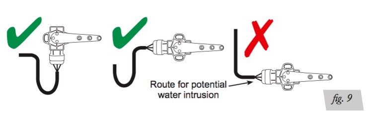
5. Reconnect the battery once the system is completely installed. NOTE Keep proper drip loops and use proper bend radius for wire bundles (fig. 9).
INSTALLING AIR LINES
1. Route and attach the air lines from the manifold to the air springs and from the manifold to the filter, as well as from the filter to the tank, if not mounting filter directly to tank. • Route air lines free from abrasive edges and heat sources.
2. Attach air lines to the appropriate manifold ports for the air springs, filter/tank and exhaust. Air lines should be pushed in firmly, with a slight back-and-forth rotational twist – check the connection by pulling on each line to verify a robust connection.
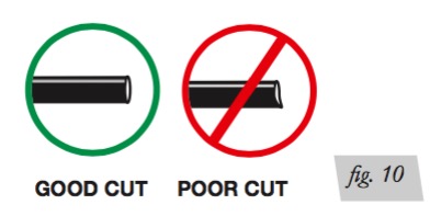
3. Exhaust port can be left open, or routed to preferred exhaust location. Routing exhaust outside of vehicle will eliminate any possibility of moisture being discharged from the port to surrounding area. Use the included hose cutter (Part number: 10530). Cut all hose ends as squarely and as smooth as possible (fig. 10).
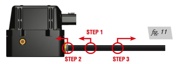
To release the air line from the connection (fig. 11), first release all air from the system. Push on the line (step 1), depressing the ring towards the fitting (step 2), and then pull the hose out of the fitting (step 3)
HELPFUL AIR LINE TIPS
4. Minimum hose bend radius
• 3/8” hose = 1.5” hose bend radius.
• 1/4” hose = 1” hose bend radius.
5. Hose to fitting
• No side loading on fitting from hose.
• Hose straight for 1” before bending.
6. Hose cutting
• Cut hose perpendicular to hose length.
• Inspect hose for scratches that run lengthwise on hose prior to insertion. • Use the included hose cutter.
MANIFOLD
BEST PRACTICE IS TO LOCATE THE MANIFOLD UNIT INSIDE THE VEHICLE. IF EXTERNAL MOUNTING IS DESIRED, THE MANIFOLD SHOULD BE LOCATED IN AN AREA SHIELDED FROM DIRECT WATER SPRAY FROM TIRES OR CAR WASHES.
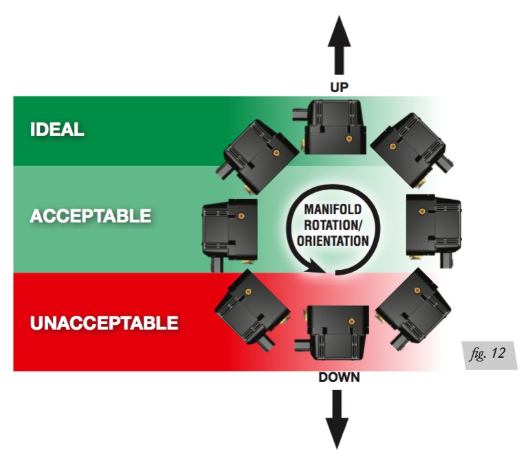
1. Position the manifold in desired location. Make sure the manifold mounting surface is flat. When mounting the manifold, do so either horizontally or vertically, with ports and connector facing toward the ground. Do not mount the manifold upside down. Proper manifold mounting will help prevent water from settling in areas sensitive to freezing (fig. 12).
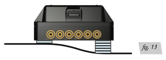
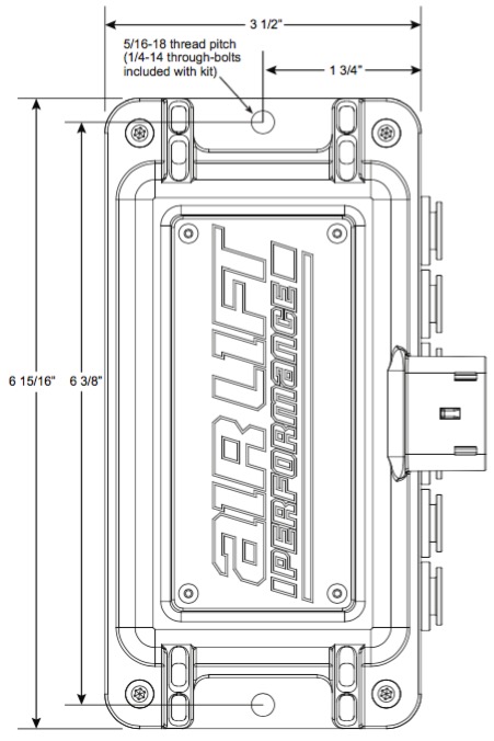
2. Fasten the manifold using the supplied hardware. If the mounting surface is not flat, add washers or a spacer to lift the manifold up over surface irregularities (fig. 13). In addition to the provided self-tapping screws, the manifold mounting holes are threaded and can be secured with 5/16-18 bolts (also supplied).
3. A manifold mounting template can be found on page 27. fig. 13 ACCEPTABLE UNACCEPTABLE fig. 12 DOWN UP MANIFOLD ROTATION/ ORIENTATION IDEAL NOTE CAUTION MN-946 11
Installation Manual
COMPRESSOR (OPTIONAL)
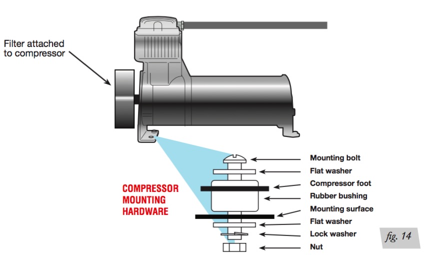
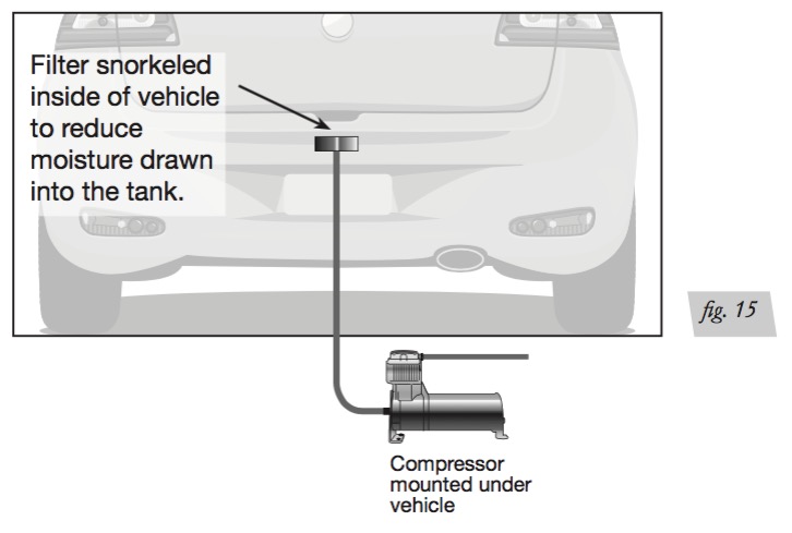
1. Prepare the compressor intake. If it is mounted inside the vehicle, attach the filter to port on end of compressor (fig. 14). If the compressor is located outside the vehicle, snorkel the inlet filter to dry location inside vehicle using components supplied with compressor (fig. 15).
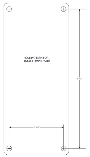
2. Center-punch and drill four holes using the compressor or the template on page 29.
3. Secure the compressor using the supplied hardware (see installation diagram).
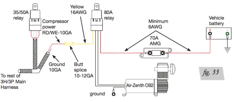
NOTE: If using an Air-Zenith compressor see figure 33 on page 21.
IF THE PRESSURE-BASED SYSTEM IS ALREADY INSTALLED BEFORE HEIGHT SENSOR INSTALLATION, MAKE SURE TO TURN OFF RISE ON START TO AVOID UNINTENDED AIRING UP. (SEE USER GUIDE.)
HEIGHT SENSORS
Installation of height sensors is a trial-and-error process and requires patience. The goal is to use as much of the sensor range as possible which will maximize height adjustment accuracy.
Determining Height Sensor
Mounting Point
1. Choose a solid mounting point on the body or frame that will not deflect. Anything that moves is not a good mounting point. For best system performance, mount the sensors in the same location on the driver’s and passenger’s sides of the vehicle. This will ensure that the sensor range is equal side to side.
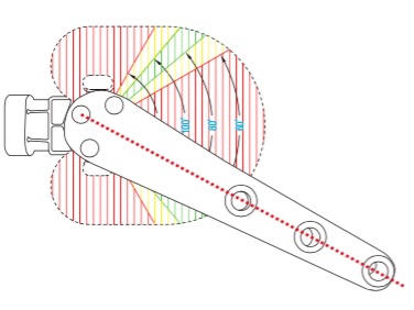
2. The sensor can be mounted in any direction and will still work as long as the sensor arm base’s extruded point is pointing toward the connector when the sensor arm is at its mid-position. The height sensor assembly is supplied in position A. Remove the arm to reposition it to B or C but keep the extruded point in the direction of the connector. The orientation of the connector must be either facing down or parallel to the ground to avoid water accumulating on the connector and making its way into the sensor. Also, mount the sensor where the arm will be mounted opposite or 90 degrees from the connector wiring if possible. If not possible, ensure the wiring harness is secured away from arm travel so it will not get caught up when the arm cycles (fig. 16).
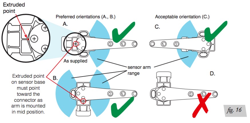
Do NOT position sensor with connector up, or with point on sensor base pointed anywhere but at the sensor connector when arm is in its mid position.
3. Find a point where the sensor will be directly above the lower linkage mounting surface. It may be necessary in some applications to fabricate a bracket to locate sensor in appropriate position.
4. Make sure that the sensor and sensor arm clear the vehicles suspension, wheels, and any other moving parts. This includes steering the wheels all the way to the lock position left and right to ensure proper clearance. Provide enough clearance to compensate for heavy load/movement that can’t be seen from manual/physical articulations.
5. Keep the sensor and wires away from heat sources and moving parts that will create wear and may damage these components.
6. Understand whether the suspension or wheel assembly is the limiting factor when the vehicle is aired out. This will ensure proper accommodation of sensor arm travel.
7. If using self-tapping screws into the frame, make sure there are no wires or brake/air/ fuel lines on the other side before installing screw.
FLOOR JACKS CAN BE DANGEROUS. WHENEVER USING A FLOOR JACK, MAKE SURE IT IS RATED FOR THE LOAD IT IS LIFTING. CHECK THE VEHICLE OWNER’S MANUAL FOR INFORMATION ABOUT WHERE TO PLACE THE JACK. BEFORE RAISING THE VEHICLE, PLACE WHEEL CHOCKS IN FRONT AND BEHIND THE WHEELS TO PREVENT THE VEHICLE FROM ROLLING. ALWAYS USE JACK STANDS TO SUPPORT THE VEHICLE. NEVER GET UNDER OR PLACE ANY BODY PARTS UNDER A VEHICLE THAT IS SOLELY SUPPORTED BY THE JACK.
SELECTING SENSOR LOCATION
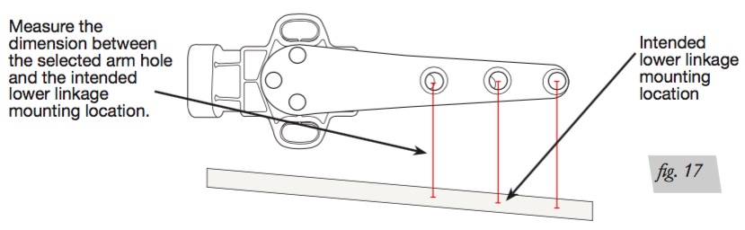
1. Mark on the vehicle the intended sensor mount location to maintain consistency in measuring methods in the next several steps. After finding a potential sensor location, measure the suspension travel, which will determine the proper arm hole. Exhaust the air springs, disconnect the air lines and jack up the suspension to its lower limit position. Take the measurement between the selected sensor arm hole with the arm at its midpoint and directly below the intended lower linkage location (fig. 17).
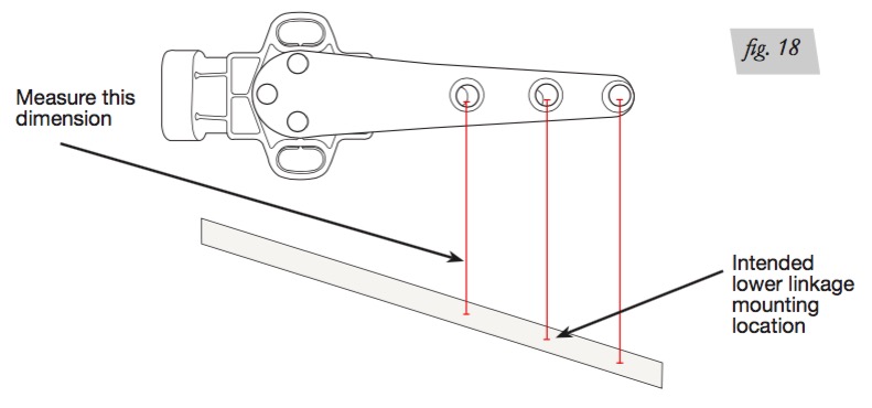
2. Reinstall air lines and cycle the suspension to get to the upper limit position again, measuring between the sensor arm’s middle position and directly below the sensor arm hole mounting to the lower linkage ball joint (fig. 18). The difference between these two values will be the full suspension travel range.
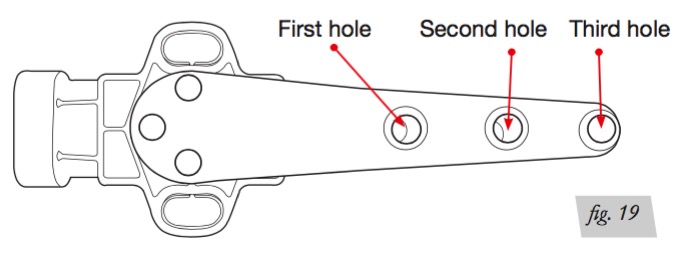
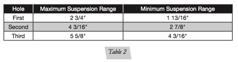
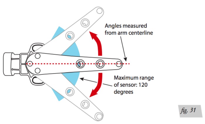
SELECTING SENSOR ARM HOLE Max angle of travel for this sensor is 120 degrees, which can be correlated to the necessary suspension travel as seen in the table below (table 2). Any significant over-extension or over-compression may damage and possibly destroy the sensor or sensor linkage.
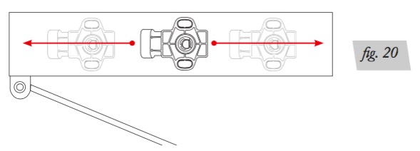
The sensor should be mounted so the measured travel falls near one of the maximum suspension range dimensions. Move the sensor closer or farther from the suspension pivot point to achieve this measurement. (fig. 20).
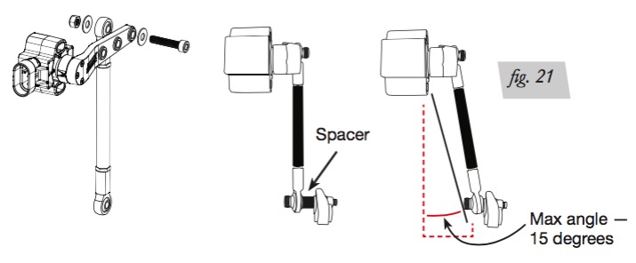
MODIFYING LINKAGE ANGLE
After selecting the location of the sensor and the arm hole to be used, determine the lower mounting point. Ensure the angle between the mounting point and the sensor arm is less than 15 degrees. Any more angle than that, will put unwanted stress on the components. Use the supplied spacer on the lower mounting point to get the angle closer to vertical with respect to the sensor arm (fig. 21).
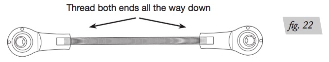
LINKAGE ASSEMBLY/MODIFICATION
1. Locate the linkage and ensure the rod is threaded all the way on (fig. 22).
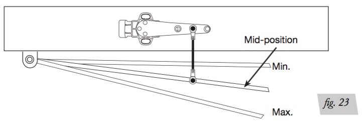
2. Next put the suspension in the mid-position with respect to full suspension travel (fig. 23).
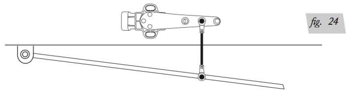
3. Fasten by finger tightening the linkage to the sensor arm and ensure the sensor arm is at mid-position with respect to the sensor (fig. 24).
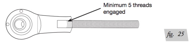
4. Loosen if needed in order to extend to reach the lower mounting point. If loosening the linkage to extend it is required, make sure to have at least 5 threads of engagement on both ends (fig. 25).
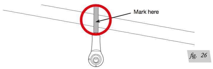
5. If shortening the rod linkage is necessary, mark the rod cover w
HEIGHT SENSORS, CONT. FROM PAGE 15
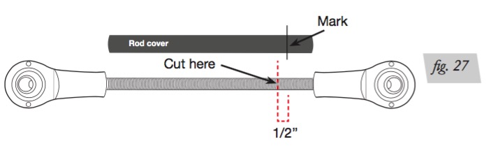
6. Remove the rod linkage from the sensor arm and measure 1/2” back from the mark. This will show where to cut the rod (fig. 27).
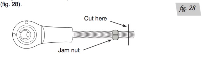
7. Before cutting the rod, thread the jam nut back on the rod. Use the nut to deburr the rod end. (fig. 28).
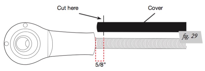
8. Cut the rod cover 5/8” shorter than the rod length with the rod assembled on one end after cutting (fig. 29).
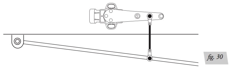
9. Assemble linkage back together, and fasten it to the sensor arm and lower mounting location with supplied hardware (fig. 30). Temporarily secure the sensor in its intended location including using the height sensor spacer that is provided.
VERIFYING SUSPENSION RANGE
Use the paper height sensor tool on page 25 or electronic sensor tool in the display to make sure the range is sufficient to provide accurate measurements (fig. 31). (See User’s Guide) Next, manually air the vehicle up and down to see if there is any issue with the travel of the sensor using the height sensor install tool. After confirming that the range is correct and adequate, permanently secure the position of the sensor using the supplied hardware. Complete this for all four sensors. To verify range using the electronic sensor tool, start with the vehicle at its lowest height. The sensor tool should display “range low” below each corner. Manually air up the front corners of the vehicle to their maximum height. Both front corners should then display “OK.” Manually air up the rear corners to their maximum height. Both rear corners should then display “OK.” It may be necessary to repeat these steps by raising the rear first, to see if results vary. For any corners that do not display OK, sensors will need to be adjusted to be within the acceptable limits, or increase the overall range (stroke). Once the system is completely installed and system calibration is done, if any of the height sensors are out of range, there will be a warning message and the affected corner’s visual indicators will not move with pressure adjustments. See User’s Guide for more information.
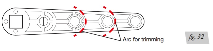
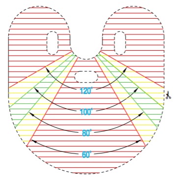
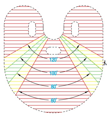
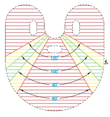
MODIFYING SENSOR ARM Follow the arcs around the appropriate holes to make the arms shorter. Keep the smooth, rounded contour of the end of the arm (fig. 32).
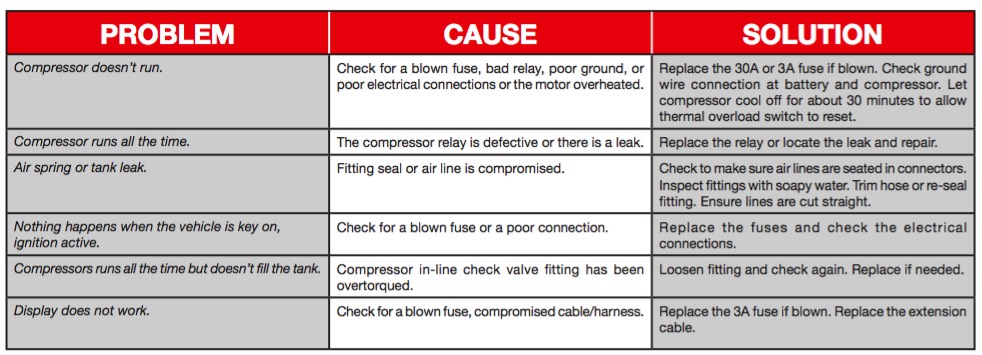
Troubleshooting Guide
Leak Testing and Detection
1. A leak can be defined as a loss of pressure of more than 5 PSI over an 8-hour period. Be aware that ambient temperature change has an effect on pressure that may seem like a leak. For example: a change of 10 degrees F up or down from your baseline will have an approximate gain or loss of indicated pressure of 2 PSI. If a leak is suspected after including any temperature change, proceed to step 2.
2. Spray soapy water (1/5 Dawn® brand dish soap to 4/5 water) on suspect fittings and hose connections and look for any bubbling caused by air leakage.
3. Fix leaking connection (review page 9 for help on NPT fittings and air line connections).
4. Wipe down sprayed connections with rag to remove any residual soapy water. Dawn® brand dish soap will not corrode the metals (aluminum, brass, steel) with which it comes into contact.
PERMISSABLE MODIFICATIONS
1. If extending the height sensor harness is necessary because of the size of the vehicle, order one of two kits: a. 27700 Kit-Height Sensor 4’ Ext (2 extension harnesses) b. 27701 Kit-Height Sensor 8’ Ext (2 extension harnesses)
2. If it is necessary to extend the display cable beyond the 4-foot cable that is supplied, purchase a USB A/M adapter extension of up to 8 feet. Use an off-the-shelf USB 3.0 cable if possible.
3. If using an Air-Zenith OB2 compressor, follow the wiring diagram below (fig. 33). The 70A fuse, relay, etc. are supplied with compressor. Wiring requirements for the compressor should follow manufacturer’s recommendation.
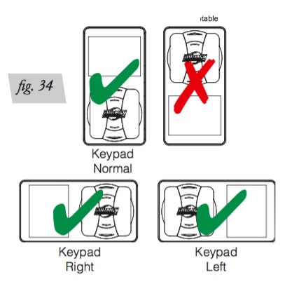
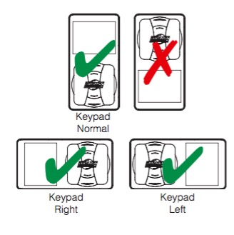
4. The keypad on the 3H/3P display can be rotated for horizontal applications but it must not be rotated so that the keypad is above the screen (fig. 34). It will not power up in this position.
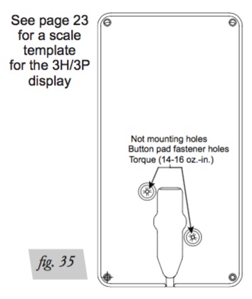
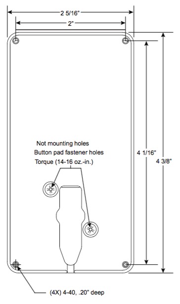
a. Rotate the keypad after removing the two screws on the back of the 3H/3P display unit (fig. 35). Once they are removed, the keypad can be pulled out and rotated.
b. Using light and even pressure, push the keypad into the display until it is flush.
c. After rotating the keypad, re-fasten the screws to the torque of 14-16 oz.-in. Do not overtighten.
d. See the User Guide for additional information about display options.
5. Extending the compressor power and ground wires is not recommended. It is permissible to remove a portion of the battery power and ground wires to extend the compressor wiring if necessary, keeping the same overall harness length. This will keep the voltage drop be within industry standards. Failing to do so could decrease the life of the compressor.
Displaying Mounting Template
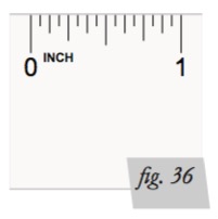
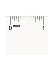
IMPORTANT: PRINT THIS MANUAL AT 100% SCALE. THIS MANUAL CONTAINS DRILLING TEMPLATES, WHICH WOULD BE RENDERED INCORRECT IN DIMENSION IF PRINTED WITH ANY SCALING. USING AN INCORRECT TEMPLATE TO DRILL HOLES MAY CAUSE DAMAGE TO YOUR VEHICLE. REFER TO THE ONE-INCH SCALE (FIG. 36) AND USE A MEASURING TOOL TO CONFIRM THAT THE PRINTED SCALE MEASURES ONE INCH TO VERIFY PROPER SCALE. IF THIS IS PRINTED AT ANY SCALE OTHER THAN 100%, THE INSTALLER COULD END UP DRILLING IN THE WRONG LOCATIONS ON THE VEHICLE.
Cut out the height sensor tools and position each one as shown at right depending on the height sensor orientation. It would be a good idea to make copies of this page in case the tools are damaged during installation. Make sure to copy at 100% so the tools are the correct size. The drawing to the right is not to scale.
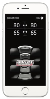
Download the App for the Best #lifeonair The Air Lift Performance 3 mobile app allows for full integration of your new 3H/3P control system on compatible mobile devices. Simply download the FREE app to not only take full control of your system, but to always have the latest system firmware with updates directly from the app. For iPhone: air-lift.co/3app For Android: air-lift.co/android Users can also search “Air Lift Performance” in either the Apple App Store or Google Play
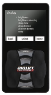
DISPLAY
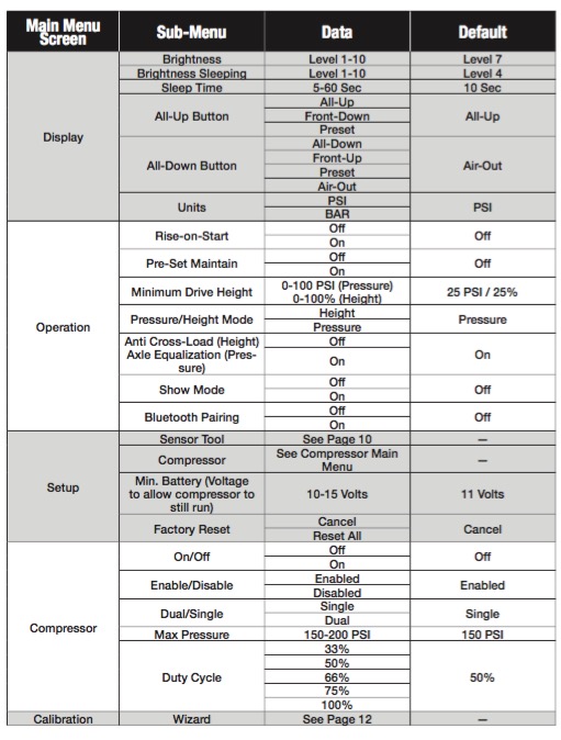
BRIGHTNESS Set the brightness for the display while in use.
1. Level 1-10
2. Use the up and down buttons to increase or decrease luminosity in 10% increments.
3. Level 7 (default)
BRIGHTNESS SLEEPING
Set the brightness for the display after it goes into sleep mode.
1. Level 0-10
2. Use the up and down buttons to increase or decrease luminosity in 10% increments.
3. Level 4 (default) SLEEP TIME Set the amount of time it takes to revert back to the main screen and for the display to go to sleep. 1. 5-60 seconds. 2. Use the up and down buttons to increase or decrease time in 1-second increments. 3. 10 seconds (default) ALL-UP BUTTON Set function for the all-up button. 1. All-up (default) 2. Front-up 3. Preset ALL-DOWN BUTTON Set function for the all-down button. 1. All-down 2. Front-down 3. Preset
4. Air-out (default) UNITS Set units of measure to PSI or BAR. 1. PSI (default) 2. BAR
SETUP
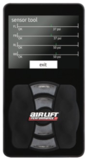
SENSOR TOOL (HEIGHT MODE MUST BE ENABLED)
This tool is used to ensure that the range of the height sensors as installed are sufficient to provide optimal accuracy for the system. (Each time that this tool is used it will reset and initially show low range until the suspension is cycled to tell the system its range.)
1. At any time press the “Preset Ride” button to exit the tool.
2. By cycling the suspension up and down, the tool will determine the following:
• Range low – Not enough range in the sensor to portray accurate data.
• OK – The range of the sensor is adequate for accurate data.
• Limit – The range of the sensor is at or beyond the bounds of acceptable data.
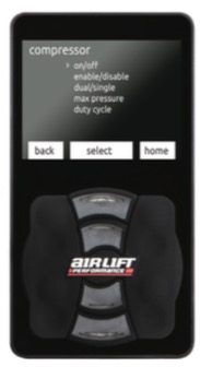
COMPRESSOR* (SETUP) ON/OFF
Control the compressor manually. In the default setting of “Off” the compressor will operate normally. Selecting “On” will activate the compressor for troubleshooting.
1. Off (default)
2. On ENABLE/DISABLE Enable or disable the compressor until the next ignition cycle.
1. Enabled (default)
2. Disabled
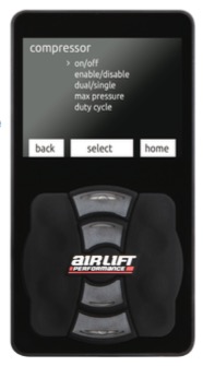
COMPRESSOR (SETUP, CONT.)
DUAL/SINGLE
Set based on whether a dual or single compressor setup is installed. If using a second compressor and harness, dual must be selected for proper operation.
1. Single (default)
2. Dual
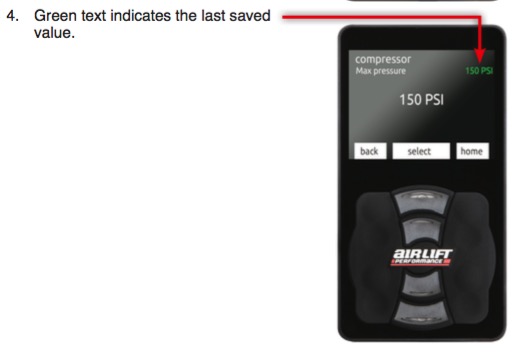
MAX PRESSURE
Set the maximum tank pressure. The compressor will turn on at 15 PSI below max tank pressure.
1. 150-200 PSI or 10342-13789 mBAR
2. Holding the up or down button quickly cycles between 150 PSI/10342 mBAR and 200/13789. A single press changes pressure one increment at a time.
3. 150 PSI (default)
DUTY CYCLE
This is for the user to set the compressor duty cycle. Setting the duty cycle higher than the manufacturer’s recommended value may cause compressor damage. See Page 22 for compressor duty cycle and working pressure.
MINIMUM BATTERY VOLTAGE
Set minimum battery voltage required to allow compressor to turn on. 1. 10-14 volts 2. 11 volts (default)
FACTORY RESET
Resets all settings and calibration back to factory default. 1. Cancel (default) 2. Reset all Cycle ignition to complete the factory reset.
Calibration
WIZARD
Run this program to complete calibration. At any time, cancel calibration by pressing “stop.”
1. Make sure the vehicle is on a level surface and select “Yes.”
2. Verify that the front wheels are straight to prevent damage to fenders, then select “Yes.”
3. Verify nothing is under the vehicle that could cause undercarriage damage, then select “Yes.”
4. Verify that the manifold is securely mounted, then select “Yes.” An unmounted manifold will not allow Preset Maintain to function properly.
5. Determine how many compressors are in use. If using a single compressor, select one. If using two compressors with the second compressor harness (part number: 27703) select two.
6. If height sensors are installed, select “Yes.” If running as a pressure only system, select “No.” If only running pressure, system will now skip to step 8.
7. If height sensors are installed, select whether to calibrate them automatically or manually. Most vehicles can be calibrated automatically. The manual option can be used when there is a custom setup where there may be concern about component interference at either high or low limits.
8. After selecting “Yes” the system will begin calibration. Selecting “No” will exit the calibration wizard.
9. System checks to make sure manifold is mounted in a proper orientation.
10. System is calibrating the accelerometer.
11. System is now calibrating the front axle for Pressure mode.
12. System is now calibrating the rear axle for Pressure mode. If using the system for Presssure only, calibration will complete after this step
13. Height Sensor Calibration (Upper) a. If Auto Sensor Calibration was selected, the system will cycle the suspension to calibrate its upper limit position. b. If Manual Calibration was selected, the system will now ask for the user to set the “Upper Limits.” Do this by using the manual buttons to raise the suspension to its highest setting on all four corners. Press the middle button when complete.
14. Height Sensor Calibration (Lower) a. If Auto Sensor Calibration was selected, the system will now cycle the suspension to calibrate its lower limit position. b. If Manual Calibration was selected, the system will now ask for the user to set the “Lower Limits.” Do this by using the manual buttons to lower the suspension to its lowest setting on all four corners. Press the middle button when complete.
15. System will now check Height Sensor vehicle wiring (Only completes this if user selected Auto Sensor).
16. The system will now perform a movement calibration for height mode.
17. Once it has run through the calibration wizard successfully, it will say “Calibration Successful” and the system will then be ready for use.
Calibration Detail Explained
AUTO SENSOR LIMITS
When the program is completing the auto sensor calibration, make sure the wheels are straight and all people stand clear as the vehicle will move up and down during calibration. The user doesn’t have to do anything during this portion of the calibration.
MANUAL SENSOR LIMITS
Below is what is being completed during the wizard’s manual sensor calibration. Use this option when making a custom setup where there may be concern about component interference at either high or low limits. (e.g. Wheel to fender interference – if the system is aired out and the wheel and fender make contact before the suspension can reach its limit.)
1. Set upper limit
• Use the manual buttons to set the upper height sensor limit.
• Press the ride preset button to continue.
2. Set lower limit
• Use the manual buttons to set the lower height sensor limit.
• Press the middle button to continue.
3. Calibration is complete. PRESSURE Below is what the wizard is doing during the pressure calibration.
1. Front calibration – The system actuates the suspension through its range of travel to calibrate pressure mode on the front axle.
2. Rear calibration – The system actuates the suspension through its range of travel to calibrate pressure mode on the rear axle.
3. At any time, cancel calibration by selecting “stop.
HEIGHT
Below is what the wizard is doing during height calibration. The system will actuate suspension through it’s entire height range to calibrate height mode.
1. Movement calibration
• A message will indicate completion of the movement calibration.
• Press the middle button to continue.
2. At any time, cancel calibration by pressing “stop.”
MANIFOLD
Below is what the wizard is doing during manifold calibration.
1. If the manifold is mounted correctly, it will indicate “Complete – calibration successful.”
2. If the manifold is mounted incorrectly, it will indicate “Fault – calibration failed.”
3. If mounted incorrectly, follow the Installation Guide for proper mounting of the manifold and run calibration again.
Firmware Updates
MOBILE DEVICE APP
The app, which is free and requires no additional hardware, is available in the Apple App Store and for Android devices in Google Play. Search for Air Lift Performance.
• Operation of the mobile app is similar to operation of the 3H/3P controller. The main difference are:
• To access the menu screens, tap the gear in the upper right corner.
• The sensor tool is only available on the controller.
• App users will get notifications that there is a firmware update, app update or other system update.
• Firmware updates can only be made through the mobile app. After installing the system, all users should download the app and check for firmware updates. The apps are available at these links: For iPhone: air-lift.co/3app For Android: air-lift.co/android Check www.airliftperformance.com/firmware periodically for firmware updates.
SWITCHING TO LANDSCAPE MODE
Users have the option of changing the orientation of the 3H/3P controller to landscape mode. • To change modes, update the firmware and choose “Keypad Normal,” “Keypad Right” or “Keypad Left.” • While the controller can be used with the display to the right or left of the keypad, it cannot be oriented so that the keypad is above the display. • To rotate the keypad, remove the two screws on the back of the controller. Remove the keypad, rotate it to the preferred position and re-secure the screws to 14-16 oz.-in.

3H/3P DISPLAY ORIENTATION OPTIONS
ADDITIONAL INFORMATION
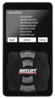
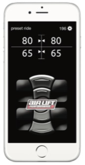
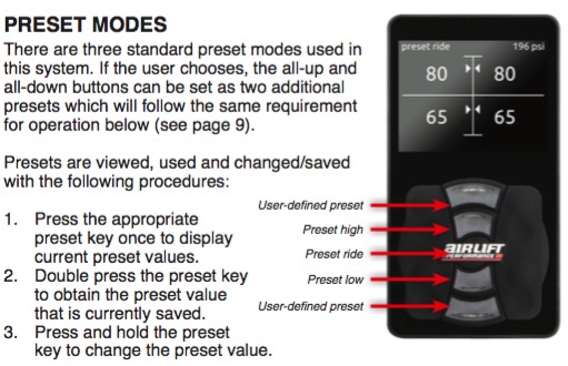
PRESET MODES
There are three standard preset modes used in this system. If the user chooses, the all-up and all-down buttons can be set as two additional presets which will follow the same requirement for operation below (see page 9). Presets are viewed, used and changed/saved with the following procedures:
1. Press the appropriate preset key once to display current preset values.
2. Double press the preset key to obtain the preset value that is currently saved.
3. Press and hold the preset key to change the preset value.
CHANGING PRESETS
1. Press and hold the preset key you want to change. The display will allow you to manually change those values using the corner keys. (Values will be shown as PSI for pressure and percentage for height).
2. Press and hold the preset key again to save your selected values.
3. To exit without saving the current preset, press any other preset button at any time.
DEFAULT SETTINGS
1. Preset low – 25 PSI (pressure)/ 25% (height) 2. Preset ride – 50 PSI (pressure)/ 50% (height) 3. Preset high – 75 PSI (pressure)/ 75% (height) Additional Information Preset high Preset ride Preset low User-defined preset User-defined preset It is possible to set the vehicle at a height that is below the minimum drive height threshold, then start driving. The 3H/3P system is a universal system and settings will be different for every user and vehicle.
About
Select this option to see what version of software is running on the system, product serial number and Bluetooth identification address. Users may need to provide this information when calling Air Lift Company customer service. The manifold or display software can be updated using the mobile app. Check www.airliftperformance.com/firmware periodically for firmware updates.