 FREE 1 to 3-Day Delivery on Orders $149+ Details
How to Install a BBK Cold Air Intake on your 1996-2004 Mustang GT
Installation Time
1 hours
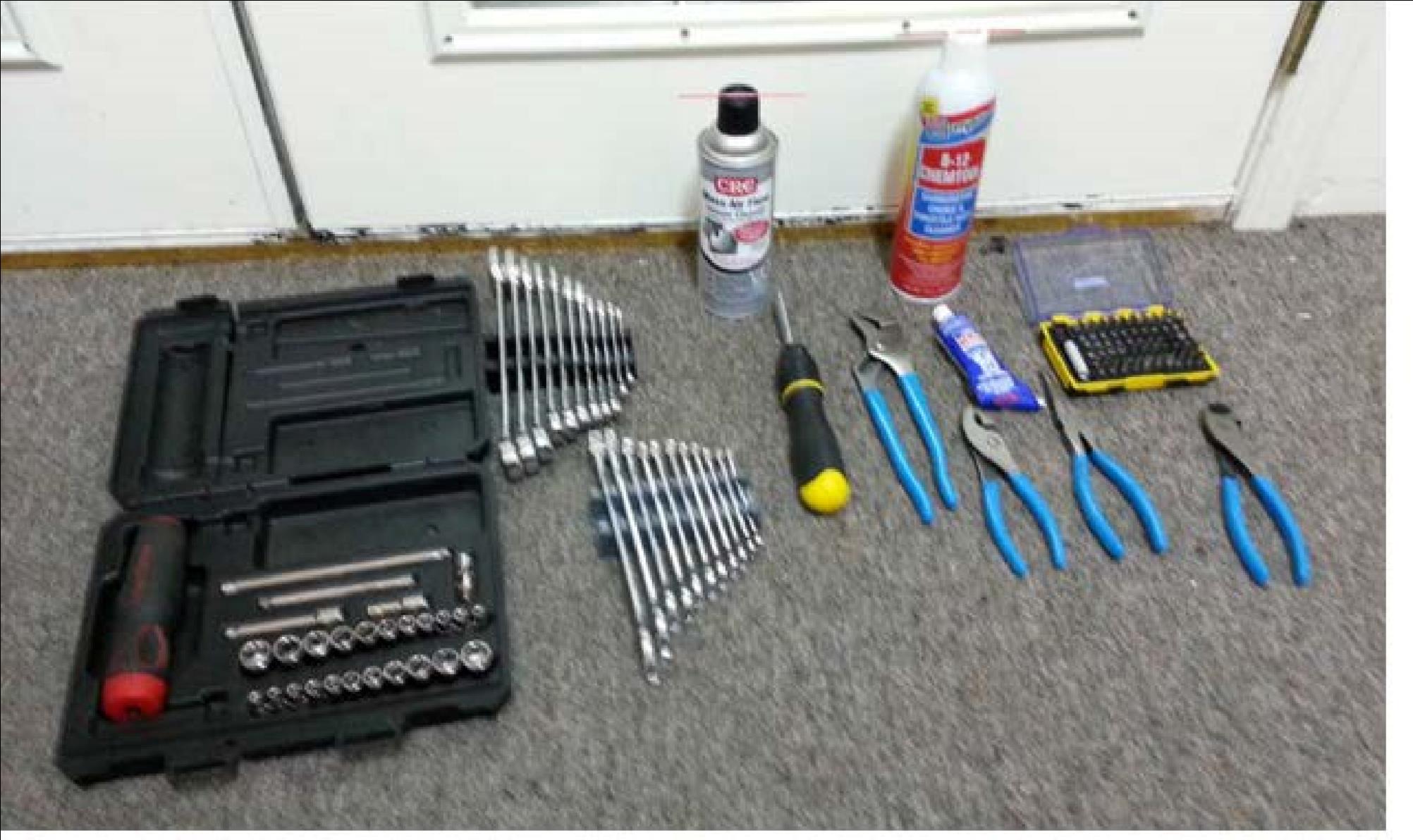
Tools Required
- 7mm socket
- 8mm socket
- 9mm socket
- 10mm socket
- 3/8¨ and 7/16¨ wrenches
- Channel locks
- RTV
- Pliers
- Needle nose pliers
- Diagonal cutters
- Clean Rags
- Carburetor/throttle body cleaner (or similar)

Shop Parts in this Guide
Installation
Definitions and Proper Operation:
- OEM – Original Equipment Manufacturer (in this case, Ford)
- MAF – Mass Air Flow (sensor)
- RTV – Type of silicone seal/adhesive
- TB – Throttle Body (what the intake will connect to)
- Using Channel Locks: Ensure that when you grip onto something that the teeth of the channel locks will dig in when you rotate/untorque something. When properly used, channel locks have amazing grip when you don't care about how it'll damage what you're trying to remove)
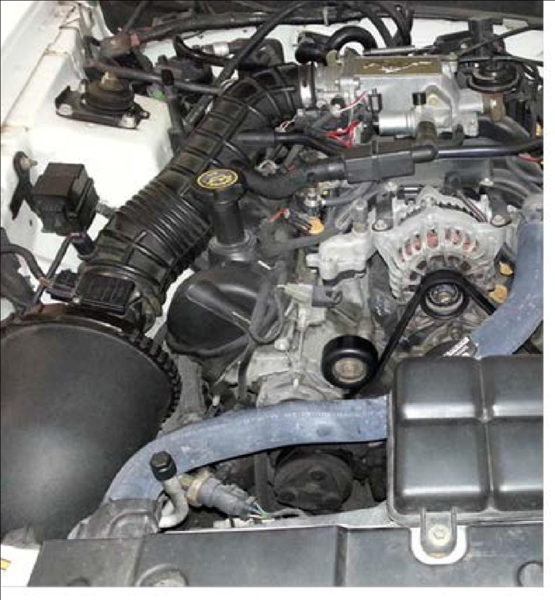
1. Disconnect battery and remove all the OEM intake hardware (SAFETY FIRST)
a. Disconnect negative battery terminal
b. Disconnect positive battery terminal
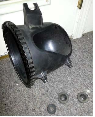
c. Save the rubber grommets that were pulled from the OEM filter housing and be very careful with the MAF sensor unit
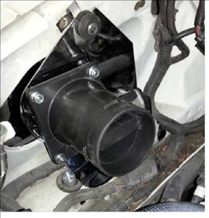
2. Remove the MAF sensor housing from the OEM parts and install it on the 90deg tube.
a. Use 10 mm socket/wrench to hold the nut side on the MAF sensor housing and on the shank side, use channel locks (disregard the damage caused by the channel locks. The parts are NOT required for reassembly)
b. Apply the RTV (refer to the application instructions on the packaging)
c. Carefully insert the fasteners and screw on the nuts. Torque to approximately 20-30in-lb (MAF sensor housing is made of plastic. DO NOT OVER-TORQUE)
3. Jack up the car and remove the hardware and tire to gain access to the wheel well and fender well (SAFETY FIRST)
a. Chalk the wheels and when the vehicle is lifted, use jack stands
b. Remove the wheel well guard using a 7mm socket and needle nose pliers (8mm or 9mm socket may be required as well
4. Install fender well mounting plate and the 90deg tube with the air filter
a. Apply the rubber trim/seal to the fender well mounting plate and cut off unnecessary length.
b. Install rubber grommets and secure the fender well mounting plate to the engine bay
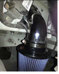
c. Slide the 90deg tube into the fender well mounting plate to allow the air filter to secure to the open-end
d. Secure the air filter to the 90deg tube using the 8mm socket
i. If you can't secure the air filter to the tube, unsecure the fender well mounting plate (refer to STEP 4.b) and instead perform that operation after this step
ii. All clamps will secure to approximately 20-25in-lb. Always consider difficulty in removing the clamp at a later date when you orientate the clamp head.
iii. Orient the MAF sensor housing side of the 90deg tube so that it's facing towards the rear of the vehicle
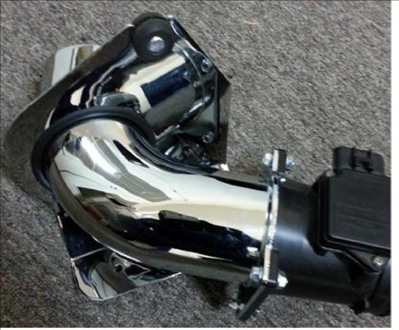
5. Prepare and install main tubing
a. Install the little grommet for the sensor to secure into it (Use the carburetor/TB cleaner as a lubricant to facilitate installation of the grommet and sensor. Ensure the sensor is oriented in such a way that air easily pass over it)
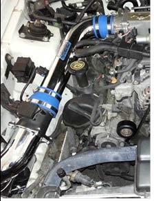
b. Install the coupler over the TB and loose-install the clamps
c. Install the main tube into the coupler
d. Install the coupler on the forward side of the tube and loose-install the clamps
e. Rotate/manipulate both the 90deg tube and the main tubing so that they fit
f. Torque clamps
6. Final assembly
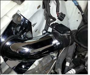
a. Remove the approximate 6-8” elbowed hose from the OEM intake tubing and install it on the main tubing and connect the other end to the little black box on the forward side of the TB plenum
b. Secure the hose just to the rear of that one to the main tubing
c. Connect the wiring to the MAF sensor
d. Give everything a look over, ensuring everything is connected and nothing is out of place then wiggle everything a bit to make sure it's all secure
e. Put a little bit of torque on the clamps to ensure they were all torqued.
f. Connect positive battery terminal
g. Connect negative battery terminal
h. Wait at least 30min (refer to RTV cure time) before firing up the engine (Fire up the engine only to test that it's properly functioning. Abstain from driving for at least a few hours.)
End of the job thoughts:
1. I had a little 1” long by 1/4” cylinder left over after the completed installation (you can see it in FIGURE 3 and 5). I thought it would install in the upper grommet on the fender well plate, but in doing so, you can't properly secure it.
2. I gave all the tubes and everything a little cleaning before I installed and didn't want to take any chances damaging the MAF sensor, so I bought a can of MAF sensor cleaner.
3. The 6-8” elbow hose isn't a 100% perfect fit. May be worth it to buy a small clamp to secure it down, although apparently unnecessary considering I haven't had any idle/performance issues and I don't have one installed.
4. I didn't use WD-40 just to be extra safe, as WD-40 is a lubricant.
5. 3 or 4-pack of rags for like $2, MAF and TB cleaner for like $6ea and I think like $5 for the blue RTV. All bought at Napa
Installation Instructions written by AmericanMuscle customer Zach Jess 2.1.13

