 FREE 1 to 3-Day Delivery on Orders $149+ Details
BBK Intake Manifold Kit ('86-'93 5.0L) - Installation Instructions
Installation Time
4 hours
Tools Required
- Flat head screwdriver
- 6" or longer extension
- Cutters or heavy scissors
- 1/2", 11/16", and 1" deep sockets,
- 1/4" ratchet (or 3/8"-1/4" reducer)
- 7/32", 1/4", 11/32", 5/16", and 10mm sockets
- 1/2", 5/8", 11/16", 1", and 1-1/8" open end wrenches
- 1/2" and 5/8" fuel line disconnect tools (spring lock type)
- 7/64", 1/8", 5/32", 1/4", 5/16", and 5mm, Allen wrenches
- T-20 Torx
- 3/8" ratchet
- Timing light
- Electric drill
- Torque wrench
- Adjustable pliers
- Teflon tape
- Thermostat housing gasket
- Lithium grease (or equivalent)
- (1) Tube of grey (or equivalent) RTV
- Large port intake to head surface gaskets
- Coolant/distilled water (depending on amount lost during installation)
- Red thread locker
Installation
1. Disconnect negative battery terminal.
2. Remove intake hose between the mass air meter and throttle body.
3. Remove the distributor. (Use a marker pen to mark the position of the rotor on the lower cup of the distributor. Also note where the distributor base is at the engine block. Your distributor should have a hash mark on it for ease of reference. This will help reassembly)
Warning!Coolant may be hot, use caution when disconnecting hoses.
4. If your manifold has a decorative plate (5.0 H.O.) on top, you will need to remove the plate. Use a T-20 Torx to remove the screws then unclip the wiring harness locator from the manifold. (These screws are usually corroded and can be very challenging to remove. We use a small hammer to tap on the screw heads to help break them loose).
5. Disconnect the electrical, vacuum, coolant, and cable connections at the throttle body, EGR valve, fuel pressure regulator, IAC valve, and the upper intake manifold. (There are vacuum lines underneath and behind the upper manifold)
6. Using a 1/2" socket and extension remove the upper intake manifold bolts, then slide the manifold towards the front of the car and disconnect the vacuum lines that attach to the rear of the manifold and the PCV. Lift the upper manifold out of the car and set it aside. (Some models have a steel bracket that connects between the upper and lower manifolds in the rear. Remove and discard this bracket if applicable).
7. Unplug the wiring harness from the fuel injectors (Be sure to only pull on the plastic plugs, never pull by the wires), lower manifold connections, and oil pressure sending unit. Set the harness back and out of the way. (It is not necessary to remove the brown ground wire that bolts to the back of the driver side cylinder head).
8. Unplug the MAP sensor and remove the screws that hold its mounting bracket to the firewall. (The MAP sensor will be relocated in a later step).
9. Disconnect the water hoses that run to the heater core feed/return pipes and thermostat housing. Remove the small water hose that runs to the EGR spacer. (To avoid spilling coolant we use a wet/dry shop vacuum to suck the water out of the hoses).
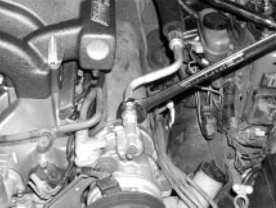
10. Remove the sensors from the lower manifold and loosen the heater core feed/return pipe with a 1-1/8 open end wrench. (It’s best to do this while the manifold is still bolted to the engine)
Warning!Fuel System may be under pressure. Use extreme caution when releasing pressure. Extinguish all open flames and ignition sources when working with gasoline and vapors. Always wear protective eyewear
11. Carefully release any fuel system pressure by removing the cap on the fuel rail near the front end of the passenger side valve cover, behind the alternator and depressing the Schrader valve using a small screwdriver or pick. (Hold a rag over the valve while releasing the pressure to avoid fuel spray).
12. Use the fuel line disconnect tools to separate the fuel feed and return lines from the injector rails.
13. Unbolt and remove the lower manifold (The fuel rails will have excess fuel in them, use caution when removing to avoid spillage)
14. Unbolt and remove the fuel rails and injectors from the lower manifold. (Check each injector to make sure that both of the O-rings are in place. The O-rings have a tendency to get stuck in the fuel rails)
15. Separate the fuel pressure regulator from the stock fuel rail. (Skip this step if you are installing an aftermarket regulator)
16. Inspect the injector tips and O-rings for cracks or damage. If you have any questionable items, we recommend replacing them (available through auto parts stores).
17. To ensure proper sealing of your new intake, thoroughly scrape and clean the head surfaces, and engine block gasket areas. (Be sure to get any debris, oil, or coolant out of the ports in the heads, and the intake valley. A wet/dry shop vacuum works well for this)
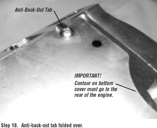
18. Apply a 1/8" bead of RTV to the bottom cover plate mounting surface of the BBK lower manifold, install the bottom cover plate using 10-32 SS-BHCS’s and fold the anti-backout tabs over each bolt head.
19. Transfer all of the sensors, thermostat and housing, PCV strainer basket, rubber grommet, and PCV from your old lower intake to the BBK lower using a new thermostat housing gasket. (Inspect your thermostat, PCV, and grommet. If they are old or damaged now would be a good time to replace them. When worn or damaged these items can negatively affect your engine’s performance).
20. Wrap the threaded portions of the pre-assembled fuel rail to Spring Lock couplers with Teflon tape and tighten the feed line into the front of the passenger side rail, and the return line into the side of the FPR mount. When the rails are installed and tightened the feed line needs to follow the angle of the valve cover pointing towards the passenger side and the return line needs to run parallel to the fuel rail towards the radiator
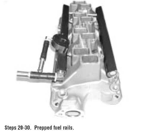
21. Attach the fuel rail mounting tabs to the fuel rails using 10-32 SS-BHCS’s with red thread-locker applied to them.
22. Place the supplied FPR gasket in the machined gasket surface area of the supplied FPR mount and attach the FPR of your choice to the FPR mount using the three 10-32 SS-SHCS’s with red thread-locker applied to them.
NOTE: Lightly lubricating all O-rings will help to ensure proper sealing.
23. Place one of the SMALL O-rings into the machined O-ring groove on the bottom of the FPR mount and attach the FPR/FPR mount assembly to the passenger side fuel rail using the two 6-32 SS-SHCS’s with red thread-locker applied to them.
24. Place the other SMALL O-ring over the fuel rail end cap into the O-ring groove. Install the end cap into the front end of the driver side fuel rail and secure it using one 10-32 SS-BHCS with red thread-locker applied to it.
25. Insert the injectors into the rails with the electrical sockets pointing outward.
26. Place one LARGE O-ring into the crossover tube port of each fuel rail.
27. Install the passenger side fuel rail/injector assembly by guiding each injector into its respective port. (The rails are designed to sit at the correct stab depth once everything is tightened. Do not force them down onto the injectors). Slip the spacer tubes behind the rail and into their seats and START threading two 1/4-20 x 1-1/2" SS-SHCS’s. (Do not tighten these bolts yet)
28. Insert the crossover tube into its port on the passenger fuel rail making sure that its bends follow the machined contour of the lower manifold and that it does not catch/snag the O-rings.
29. Install the driver side rail while guiding the crossover tube and injectors into their respective ports. In the front, slip the spacer tube behind the rail into its seat and attach using a 1/4-20 x 1-1/2" SS-SHCS. In the back use the 1/4-20 x 5/8SS-SHCS. Tighten all four of the fuel rail mounting bolts (As you tighten the rail mounting bolts the crossover tube will seat itself firmly into place).
30. Wrap the threads of two of the 3/8-18 pipe plugs in Teflon tape and tighten one into the threaded opening in the rear of each fuel rail.
31. Apply your choice of lower intake gaskets to the head surface and apply a 1/4" bead of RTV sealant to the front and back edges of the engine block. (Use this sealant in lieu of factory type end seal gaskets for best leak prevention).
32. Push the two supplied dowel pins into the two small holes in the top of the lower manifold (If your application requires a driver side throttle body do not use the studs).
33. Place the BBK lower manifold/fuel rail assembly on the engine. Install the heater core feed/return pipe assembly and tighten the 12 lower intake mounting bolts (Place the intake bolt that mounts the heater tube through the mounting tab and then tighten).
34. Install all of the lower manifold sensors into the BBK lower and install two of the supplied 3/8-18 pipe plugs wrapped in Teflon tape into the remaining holes. (The EGR spacer water return fitting is not used on the BBK lower. One of the supplied3/8-18 plugs must be installed to block it off).
35. Re-establish all lower manifold wiring connections that you disconnected in step 8 and re-connect the water hoses that run to the heater core feed/return pipes, and thermostat housing. (The large black and white wiring harness connectors should now sit behind the driver side fuel rail).
36. Firmly push the supplied vacuum cap onto the EGR spacer coolant feed fitting on the heater core feed/return pipe. Tighten the supplied hose clamp around the cap.
Installing the Fuel Rails:
(If the car has automatic door locks or an alarm, be sure to leave the driver door open while following this procedure. Otherwise the doors might lock with the key in the ignition). With the negative battery cable disconnected turn the ignition key tithe run position. While watching the fuel rails and connections touch the negative battery cable to the negative terminal of the battery for 3 seconds. Repeat this 3 times. (This will turn the fuel pump on momentarily and pressurize the fuel rails. If you have any leaking connections or fittings, this will allow you to find them before you put the upper intake manifold on). Inspect the fuel rails and injector assembly. Once you have verified that there are no fuel leaks in your system turn the keyback off.
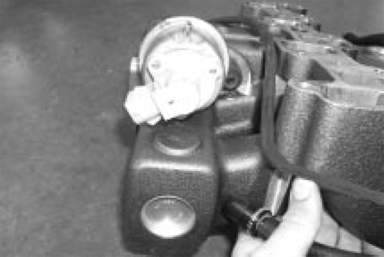
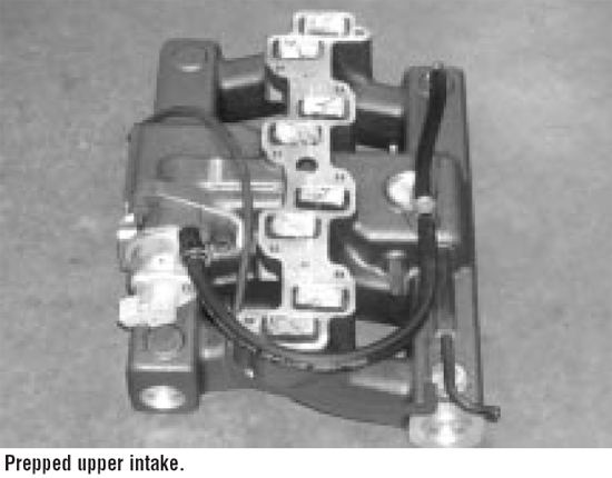
1. From the bottom of the original upper intake transfer the large steel vacuum tree and other fittings to the BBK upper (the large tube on the steel tree needs to point out to the driver side) and install the supplied pipe plug wrapped in Teflon tape into the remaining hole.
2. Install the supplied 90° vacuum fitting into the front driver side bottom corner of the upper intake.
3. Cut the supplied 3/8" hose into 2 sections. (1) 8" and (1) 15". Connect the 8" section between the 90° and T fittings. Connect the 15" section to the PCV on the lower manifold. The 15" section will connect between the backside of the T fitting and the PCV once the upper manifold is installed.
4. Re-position the electrical connector on the EGR valve. With the connector in the 10:00 position remove the fasteners and rotate the connector to the 2:00 position. Re-attach the fasteners. The connector should be pointing up and out to the passenger side of the car.
5. Transfer the EGR valve, throttle body*, and throttle cable bracket to the BBK upper *(5002 customers will install the supplied throttle body and transfer the IAC valve) using the 5/16-18 x 5/8 bolts and the supplied gaskets for the throttle body, and the stock bolts for the bracket. (If your vehicle has cruise control install the supplied spacer between the upper manifold and throttle cable bracket using the two M-8 x 1.25 x 30 SS-BHCS. The spacer only installs one way).
6. Connect the supplied vacuum hose to one of the small vacuum ports on the steel tree. This will run under the upper intake and connect to the FPR once the upper is installed. (You will not be re-using the original FPR vacuum hose).
7. Lay the supplied gasket over the dowel pins on top of the lower intake. (The gasket will only fit over the locating pins one way). Using the dowel pins as guides set the upper manifold onto the lower and torque the supplied mounting bolts to 10-13Ft-lbs.
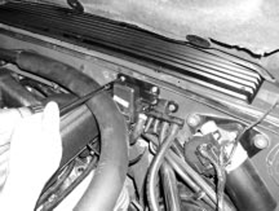
8. If applicable; SLIGHTLY loosen the large air conditioning hose connection on the back of the compressor until the hose can be swiveled. (1/4-1/2 turn should be all that is need to loosen the connection enough for this). Gently lift the hose to its maximum height where it curves to run along the firewall (without bending) and re-tighten the connection.
9. Re-establish all upper manifold connections that you disconnected in step 5.
10. With the MAP sensor plugged in, hold it up to the firewall and determine the best mounting location. Using the supplied self-drilling screws relocate the MAP sensor on the firewall.
11. Using the supplied gasket and the final 6 10-32 SS-BHCS attach the plenum cover to the upper manifold.
12. Install and connect the distributor, cap, and spark plug wires (be sure to line up your reference marks when inserting the distributor).
13. Connect the intake hose to the mass air meter and throttle body.
14. Connect the negative battery terminal.
15. Refill the radiator with your choice of coolant/water mixture.
Note:If you think you may have dropped dirt, debris, or coolant into the intake valley of the engine during this installation, we STRONGLY RECOMMEND that you change your oil and filter before attempting to start your engine.
16. Start the engine and adjust the ignition timing to your preferred setting. (Stock setting is 10° ATC )
Warning!Always use caution when opening the radiator cap! The system may be under pressure and the coolant might be hot.
17. It may take a bit of driving to circulate any ingested air out of the engine cooling system. Keep watch over the temperature gauge and be prepared to add fluid until you are sure the system is full. You may need to top off the reservoir/radiator more than once after this install.
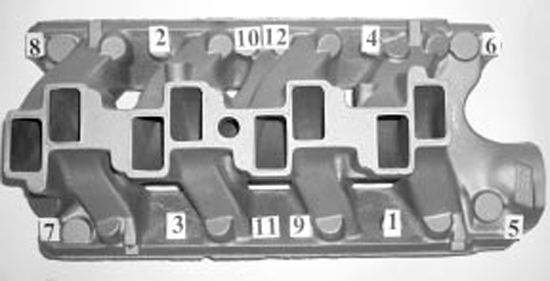
Torque Sequence
- Step 1 - 12 ft-lbs.
- Step 2 - 18 ft-lbs.
- Step 3 - 24 ft-lbs.
Installation instructions provided by BBK
Related Guides
-
Installation
-
Installation
-
Installation

