 FREE 1 to 3-Day Delivery on Orders $149+ Details
How to Install a BBK Chrome Ling Tube Headers in your 1996-2004 Mustang GT
Installation Time
10 hours
Tools Required
- Jack Stands (at least 2) and ramps or 4 jack stands
- Floor Jack. (2 is preferable, but could be done with 1)
- Lug nut wrench and key for wheel locks
- 2X4 or 2X6 about 12" long
- Socket Wrenches (ratchet) (1/4", 3/8" ½")
- Sockets sized 8mm, 13mm, 15mm, 21mm, 24mm ( ¼", 3/8", ½")
- Deep Sockets sized 13mm, 15mm, 18mm (3/8". ½")
- Socket Extensions 3", 6", 12" (1/4", 3/8", 1/2")
- Open-end wrenches sized 10mm, 13mm, 15mm, 18mm
- Zip-ties
- Open-end stubby wrench 13mm
- Torx bit sized E8 (1/4")
- Large crescent wrench
- Breaker Bar (½")
- Long screwdriver or pry bar
- Hammer
- Pliers
- Wire cutters
- Coat hangers

Shop Parts in this Guide
Please Note: You will need a shorty mid pipe with these headers either an H/X pipe. Install can be done with common hand tools, air tools could be used for a lot of the steps and they would make the job go faster, but I did the entire job with hand tools and little elbow grease. It will be necessary to take the car to get an alignment after install.
Removal procedure:
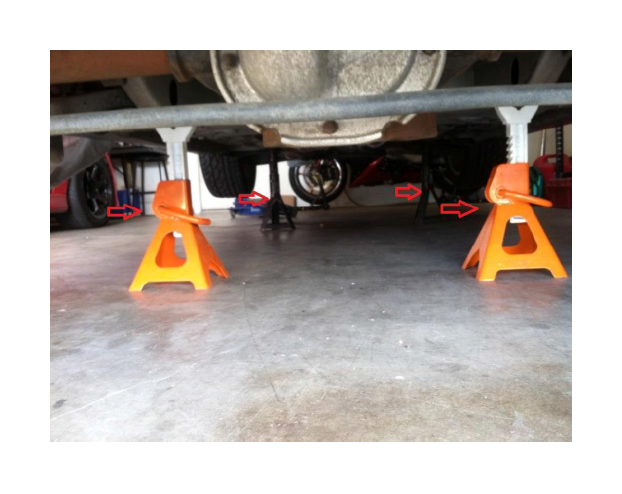
1. Loosen the lug nuts on the front wheels before raising the car. Jack up the car and support it on some combination of jack stands and ramps. I chose to use 4 jack stands, Remove the front wheels from the vehicle.
2. Disconnect the negative terminal from the battery using an 8mm socket or box-end wrench.
3. Remove the brake calipers from the spindles on both sides of the vehicle using a 12mm socket to get the 2 bolts off.
The calipers need to be hung out of the way using a coat hanger or a strong piece of wire or rope.
I used a rope doubled up to support the caliper by running the rope through a hole in the strut tower tying around the top of the strut mount.
4. Remove caliper mount bolts using 15mm socket and breaker bar, then use standard socket wrench to finish removing the 2 bolts. Remove the rotors from both sides of the vehicle, they will slide off when the caliper mount is removed.
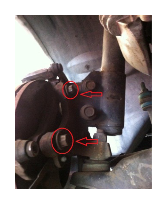
5. Remove the tie-rod ends from the spindles on both sides of the vehicle. First remove the cotter-pin holding the nut in place using pliers to bend it and pull it out. Then use an 18mm deep socket to remove the nut. Hammer on the top of the bolt after the nut is removed to drop the end joint out of the spindle. It helps to turn the wheel outward to gain access to the end joints.
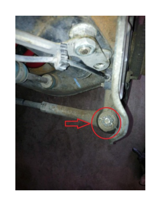
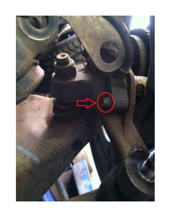
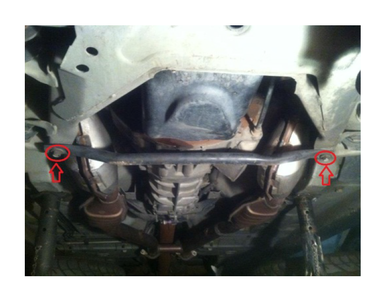
6. Remove sway bar end links on both sides of the vehicle using a 15mm deep socket on the nut and a 10mm open-end wrench on the link to prevent it from twisting. There is a flat spot in the middle of the link where the 10mm open-end wrench fits. Unbolt top and bottom nuts and remove bolt, will help later on when lowering control arm.
7. Unbolt struts from spindles by placing a jack under the control arm to jack up the control arm to compress the spring/strut.
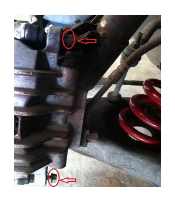
First, remove ABS sensor from the two grommets holding it to the car.
Then remove the bracket that holds the ABS sensor harness in place using a 24mm socket. Move the bracket out of the way.
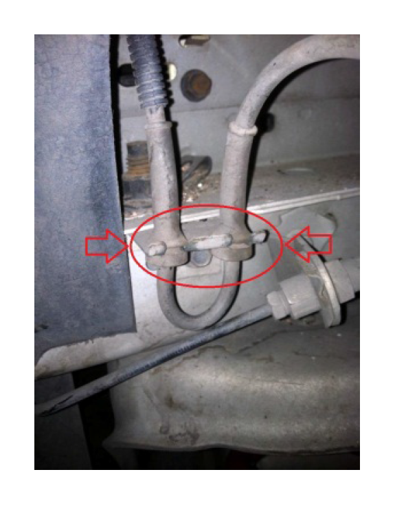
Then, using a 24mm socket and breaker bar on the nut and a 21mm socket on the bolt loosen the 2 bolts. Finish removing the 2 strut bolts holding the strut to the spindle with a socket wrench. Swing the strut out of the way. Hold the spindle in place until the ABS sensor can be removed to prevent damaging the sensor.
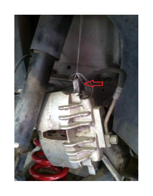
8. Remove ABS sensor from spindle using E8 Torx-bit and hang out of the way.
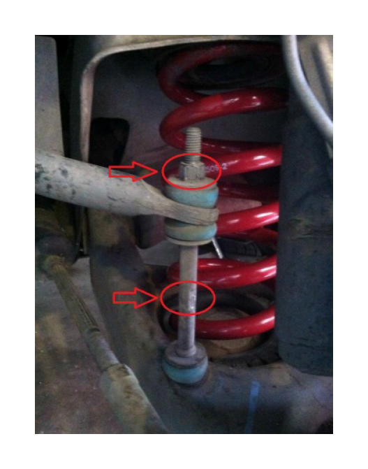
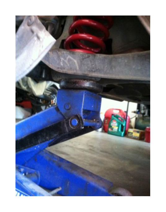
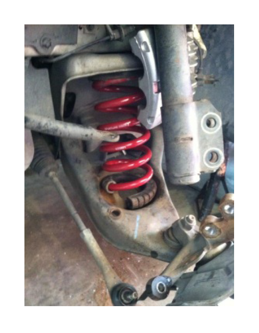
9. Slowly lower the jack under the control arm to allow the spring to expand. Allow the spring to expand to its fully uncompressed length. The spring will still be wedged in the spring perch. Push down on the lower control arm and extract the spring from its perch. If car is still on factory springs you may want to use a pry bar to help the spring out of spring perch. Be very careful doing this!! Make sure all of the pressure is off of the spring before pushing down on the control arm.
(Steps 3-9 are the same for driver and passenger side)
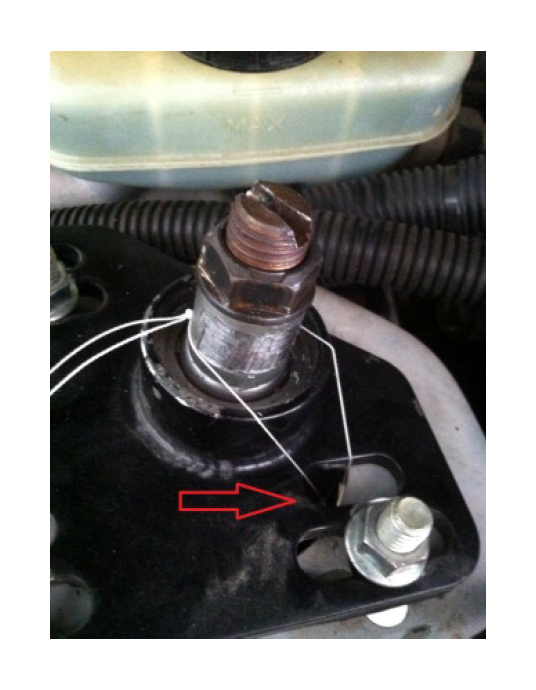
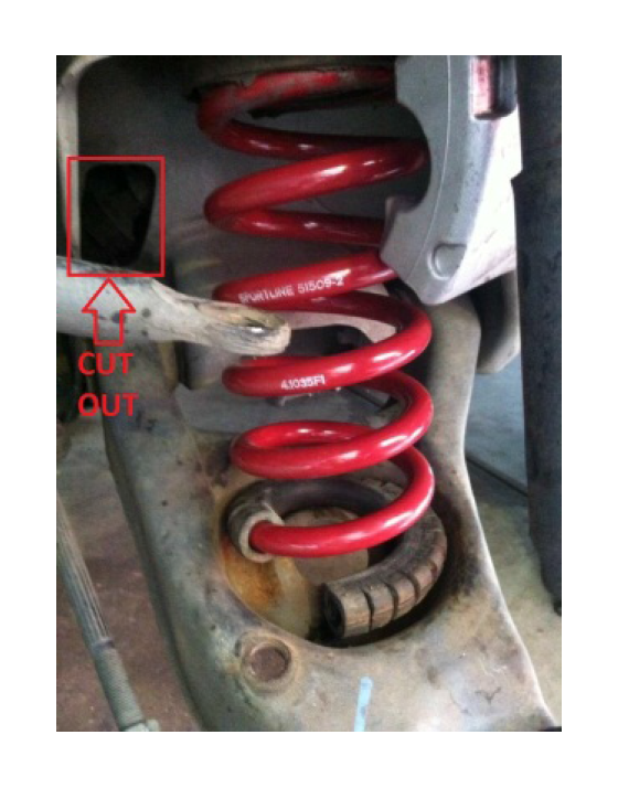
10. Remove the steering shaft nut from the bottom of the shaft where it connects to the steering box using a long extension and 13mm socket. Turning the steering wheel helps to expose the bolt.
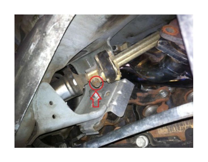
The bolt is accessed through a cutout in the K-member right behind the spring on the driver's side or from underneath the car. Pull the shaft off of the steering box. The shaft is comprised of an inner and outer sleeve. The inner sleeve can be retracted into the outer sleeve when you pull it off of the steering box.
11. Remove the steering rack from the front of the K-member using a 15mm socket on the 2 front bolts and an 18mm deep socket and extension on the 2 nuts on rear. Remove the long bolt assemblies. Pry the steering rack off of the K-member. This may take some force as the rubber bushings seem to sort of glue themselves to the K-member. Once the steering rack is pried away hang it from the sway bar using a coat hanger or zip-ties.
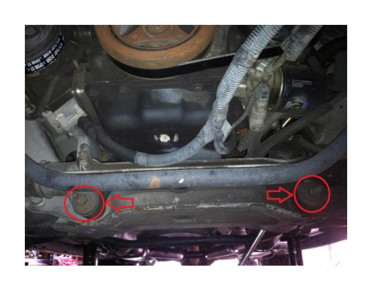
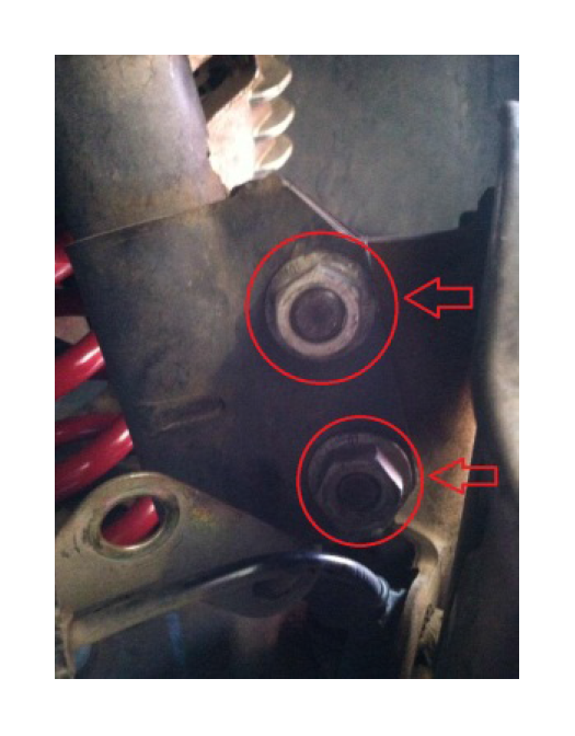
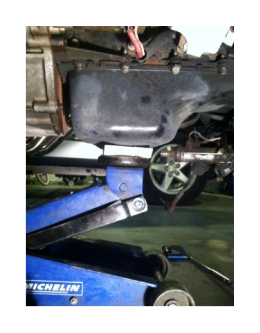
12. Remove the 2 bolts from the G-load brace on the rear of the K-member using a 15mm socket. This gives the access needed to place a jack under the vehicle and support the engine from the oil pan.
(If you don’t have an engine hoist this is the alternative to support motor)
13. Support the motor using a floor jack with a 2X6 about on top of it, get under the vehicle and jack the board up directly under the oil pan until it is firmly against the pan. Use the floor jack with the handle pointing to the rear of the vehicle to make it easier to remove the K-member out the front of the car later on.
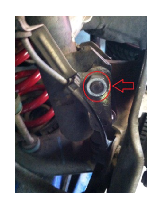
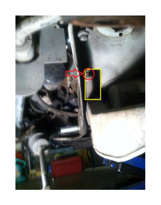
14. Remove the nut attaching the motor mount to the K-member using a 21mm socket and breaker bar with extensions to loosen the nut and finish with a socket wrench. The nut is located in the k-member cut out by lower control arm, on each side of the vehicle.
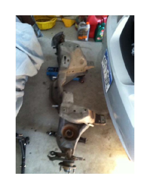
15. Remove the K-member, Support the K-member with a second jack or jack stands. Use a breaker bar with 18mm and 15mm sockets to loosen the 8 bolts that hold the K-member in place. Finish removing the bolts with a socket wrench. There are 2 bolts in the upper spring perch area on both sides of the vehicle. There are 2 bolts underneath the vehicle in the rear portion of the K-member on both sides of the vehicle. Once all 8 of the bolts are removed, slowly lower the K-member away from the vehicle making sure it is not getting hung up on anything. After the K-member is dropped away get some help and move it aside and out of the way. This is a two person job. The K-member is heavy and awkward.
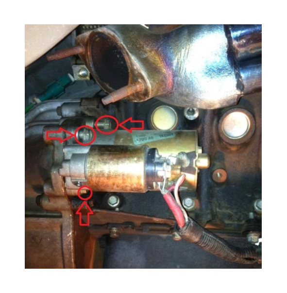
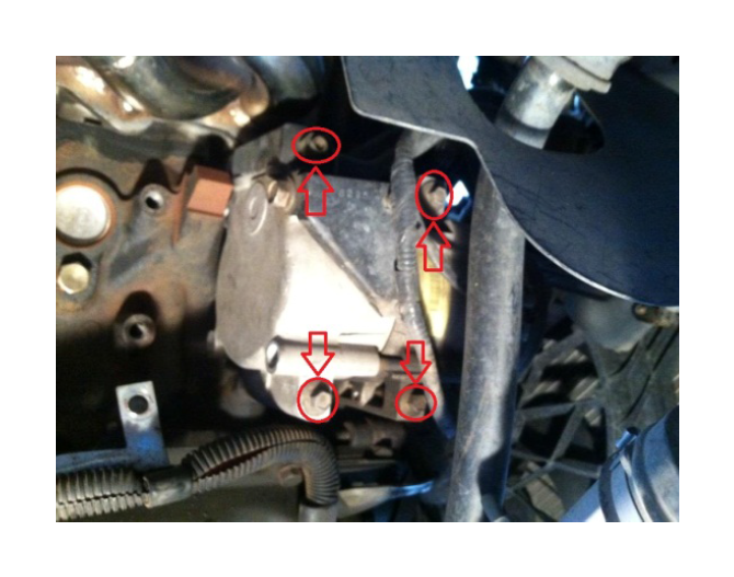
16. Remove the motor mounts from the engine block using 15mm and 13mm deep sockets. The driver side motor mount has two ground straps attached to it with 15mm nuts. These need to be removed to access the 13mm nuts that hold the motor mount to the block. Each motor mount is held in place by 3 nuts. The passenger side has a bracket that holds the starter cables and it needs to be removed before the motor mount nuts can be accessed.
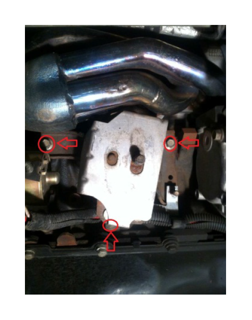
17. Remove the mid pipe section of the exhaust from manifolds and cat-back using a combination of 13mm and 15mm deep sockets and 15mm box-end wrench. The driver side manifold has the EGR fitting on the rear of the manifold that requires a large open-ended wrench or a large crescent wrench. Remove the nut from the EGR fitting and move the EGR tube out of the way.
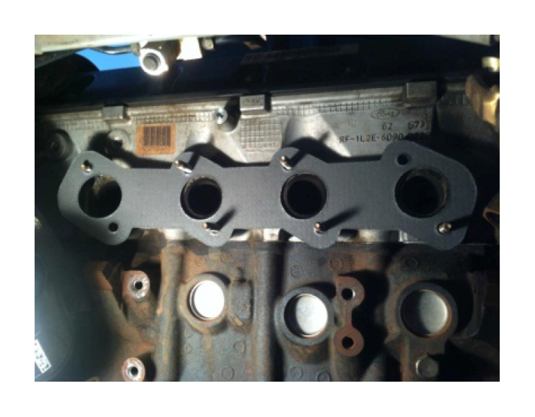
18. Remove exhaust manifolds using a 13mm deep socket and extensions. It is a straight shot to all 8 of the nuts holding the exhaust manifolds in place. Some of the studs may come out with the nuts, but they can be threaded right back in and be reused. The exhaust manifolds slide right off of the studs after the nuts are removed. Remove the exhaust manifold gaskets. (Previous owner had shorty headers installed on car.)
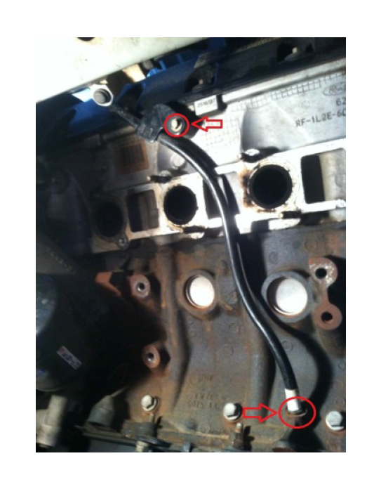
19. Remove the oil dipstick tube using an 8mm socket. The oil dipstick tube on the driver’s side of the vehicle needs to be removed before the new header can be installed. Pull the dipstick out of the tube and remove the nut holding the tube in place. Pull up on the tube and it comes out of the block. The tube goes into the block about 1 ½-2". Then cover the open hole with tape so nothing gets in it.
Install Procedure:
20. Install new gaskets onto studs provided with the headers.
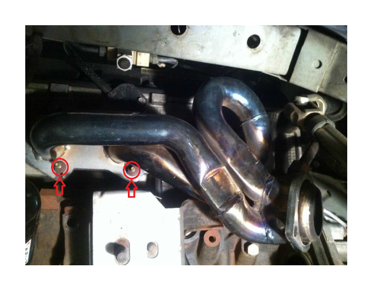
21. Install headers, a little note: it is a good idea to stuff a rag between the tubes of the header down by the collector before installing to prevent dropped nuts/bolts from getting wedged down by the collector. Slide the header flange over the studs and gasket. First reattach the EGR tube on the driver's side. This helps hold the header in place while the other bolts are being threaded on. On the driver's side the header tubes interfere with the two bottom rear studs. This requires you to place the nuts on these studs first, before fully seating the header in place or you can shave them down using a Dremel tool to cut off the portion of the stud without threads gives the necessary clearance. Most of the nuts on the driver side header were easily accessible and could be tightened with a 13mm deep socket and long extension. I used a 13mm open-end wrench to get to a couple of the top nuts. There was room to move the wrench through about a ¼- 1/2 of a turn. It was tedious but all nuts could be tightened fairly easily. Snug all the nuts down tight enough to squish the gasket and feel tight. Don't try to tighten them as much as possible because it might strip the studs out of the block. The passenger side header required a little more finesse to get in. Remove the starter to get enough room to get to the lower rear studs. Use a 13mm socket and extension to get to 3 bolts holding it.
Loosen the mounting bolts on the A/C compressor a few turns to allow it to move out of the way enough to get the header flange to slide onto the studs. Lower the motor about 3 inches to allow access to the top two rear nuts on the passenger side.
There is very little clearance between the header and frame rail on the passenger side. Tighten the top two rear nuts with a 13mm open-end wrench and a lot of patience. Using a 13mm stubby open-end wrench makes this easier, room to only turn the nut about a 1/8th of a turn each time because of interference from the valve cover. Make sure all nuts are tightened firmly.
22. Install starter, torque to 18-20 ft-lbs. Tighten A/C compressor torque to 20 ft-lbs
22. Install the oil dipstick tube by sliding it down from the top of the engine in between the 2nd and 3rd pipe from the left on the header. The tube will have to be bent slightly in order for it to clear the header flange. To make it easier remove the fuse box cover in the engine compartment to give the added clearance needed when sliding the tube back in place. Reinstall the retaining nut with an 8mm socket. Reinstall dipstick into tube.
23. Install the motor mounts using 15 mm and 13mm deep sockets and extensions. Make sure the ground straps and wiring harness brackets get reinstalled on their respective sides. Tighten down the nuts to 25-33 ft-lbs.
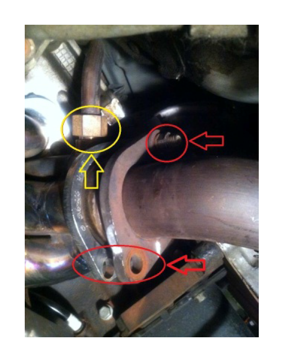
24. Connect the O2 sensor wiring harness extension to the connector on the rear of the block and O2 sensor at the header collector for each side. Use Zip-ties to keep the wires away from the headers.
25. Install the K-member. Jack the engine back to its normal height or a little above. While still supporting the engine with the floor jack, use a floor jack to raise the K-member back into the original position under the vehicle. Using 15mm and 18mm sockets reinstall the 8 bolts that hold the K-member in place. Torque lower k-member bolts to 66 ft-lbs, upper k-member bolts to 85 ft-lbs.
26. Install the motor mount bolts. Lower the engine down into position making sure the motor mounts line up properly. Using an 18mm socket and extension install the bolt that attaches the motor mount to the K-member. Torque to 110-115 ft-lbs.
27. Install steering rack. Cut the zip-ties holding the steering rack to the sway bar or what you used. Using 15mm socket and 18mm deep socket with extension reinstall the steering rack onto the K-member. Finish by tightening the bolts with the breaker bar. Torque to 35 ft-lbs.
28. Reattach steering shaft. Slide the steering shaft over the fitting on the steering box and use a 13mm socket to tighten the retaining bolt. Torque to 35 ft-lbs.
29. Install G-load brace using 15mm socket.
30. Install springs. Install the spring back into their perch by pushing down on the lower control arm and sliding them in top first with top and bottom isolators. Make sure the springs are aligned with the pigtail in the same location it was prior to removing. Using a floor jack under the control arm, jack the control arm up to compress the spring.
31. Reattach ABS sensor to spindle using E8 Torx-bit and a dab of hi-temp thread locker.
32. Reattach struts to spindles using 21mm and 24mm sockets. Use a dab of hi-temp thread locker on the threads of the bolt and torque to 170 ft-lbs
33. Reattach the ABS wiring harness bracket to the strut using a 24mm socket. Then place back on the two grommets.
34. Reattach sway bar end links using a 15mm deep socket and 10mm open-end wrench on the flat spot in the middle of the end link to keep the link from twisting. Tighten the nut until the bushings are slightly squished.
35. Reattach tie-rods to the spindle. Using an 18mm deep socket tighten the nut on the end joint. Tighten the nut until the end joint is pressure fit into the spindle back the nut off a quarter of a turn then snug it back up. Line up one of the slots in the nut with the hole that passes through the end joint and install the cotter-pin.
36. Install rotors and caliper mount to spindle. Slide the rotor onto the studs and then slide caliper mount over rotor and attach using 15mm socket. Put a dab of hi-temp thread locker on the bolts before installing on spindle. Torque the bolts to 90 ft-lbs.
37. Install caliper to caliper mount with pads on caliper mount in place. Use 12mm socket, torque to 25 ft-lbs
38. Install wheels back on using lug wrench or deep socket and torque lug nuts down to 100 ft. /lb.
(Steps 30-38 are the same for driver and passenger side)
39. Install the new shorty H/X-pipe to the headers and cat-back.
40. Attach rear O2 sensors to their respective connector on the tail of the transmission housing.
41. Reconnect negative terminal on battery using 8mm socket or box-end wrench.
42. Close the hood and lower the car down off of the jack stands and/or ramps. Take the car for a test drive. Listen for exhaust leaks and rattles.

