 FREE 1 to 3-Day Delivery on Orders $149+ Details
BBK Ceramic Long Tube Headers ('99-'04 Cobra and '03-'04 Mach 1) - Installation Instructions
Installation Time
1 days
Tools Required
- Ratchet 2 needed 3/8" or 1/2" drive to fit the following sockets
- Sockets 8mm, 13mm, 14mm, 15mm, 15mm deep, 13/16" (need two), 18mm deep, 22mm deep, 1/4" (6 or 12 point),
- Breaker bar or pipe to slide over ratchet handle
- Large adjustable crescent wrench
- Hammer
- Pliers
- Dremel or hacksaw
- Pry bar
- 2 Floor jacks
- 2 Jack stands
- 2 Ramps
- 2" x 8" this will go between the jack and the oil pan, needs to be about 10" long
- 8 4" x 4" x 12" blocks of wood to support motor (recommended but not required)
- 2 2" x 4" x 12" blocks of wood to support motor (recommended but not required)
- 4 bricks or 2" x 4" blocks of wood to chock rear wheels
- Zip ties (12" size)
- PB Blaster or some other penetrating fluid
- Blue thread locker

Shop Parts in this Guide
Installation
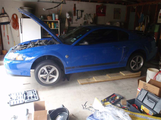
1. Back the car onto a set of ramps in a cool, covered area. Somewhere you won’t mind leaving your car for 1 Day or two. SAFETY PRECAUTIONS: Engage the parking brake and put a 2" x 4" block of wood (or brick) in front and behind of each rear wheel to make sure the car cannot move while you are working. Also, walk around the car to make sure you have a clear working space around and under the car. ALSO, DISCONNECT THE BATTERY POSITIVE TERMINAL. This is a critical safety precaution because you will be messing with the starter motor later in the install and you do not want it to be “hot”.
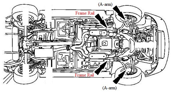
2. Begin by breaking loose each of the 5 lug nuts on each front wheel, using your mustang’s lug nut wrench. Once they begin to turn, stop and do not continue to loosen them. Next place your floor jack under the front A-arm (pictured below) and raise your car enough to slide the first jack stand under the frame rail (also pictured below). Next, jack the other A-arm up and slide the second jack stand in place under the frame rail. Once you have the car raised initially, continue to raise both sides until the front of the car is level with the rear.
3. Next, remove the wheel lug nuts from both front wheels and take the wheels off. For added safety I always slide the wheels under the frame rails, behind the jack stands. I recommend you do the same.
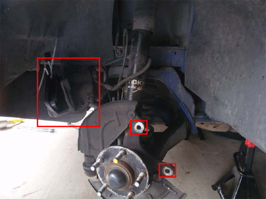
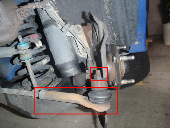
4. Before getting to the headers install, you have to remove the entire front steering and suspension assembly. Begin on the driver’s side of the car, by removing the brake caliper from the spindle. The caliper is attached by two 15mm bolts. Once these are removed, use a zip tie to support the brake caliper so that it does not strain the brake line. Also, be careful not to drop or twist the caliper so you will not damage the brake line. Next, use the pliers to remove and discard the circular clips on the wheel studs that hold the rotor down. These do not need to be replaced and may have already been removed depending on what work has already been done on the car. Now you can slide the rotor off the hub assembly and set it aside.
5. Next, straighten and remove the cotter pin that goes through the castle nut that attaches the tie-rod. Then use an 18mm deep socket and remove the castle nut itself. Now the tie-rod can fall out of the spindle, however, it may require some persuasion. If it doesn’t come out on its own, first, spray it with penetrating fluid. Let it sit for a few Mins and then hit the top of the bolt with a hammer to force it out.
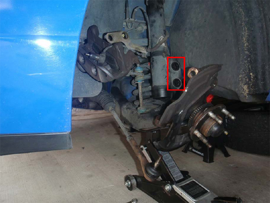
6. After this, you are ready to disconnect the strut. Place the jack under the A-arm again and raise the jack only until it puts pressure on the A-arm. Then loosen the bolts that attach the strut to the spindle. First, remove the nut that holds the ABS bracket in place using a 15/16" wrench. Then, using two 13/16" ratchet/socket combinations or one socket and one box end wrench, loosen the two bolts and remove them.
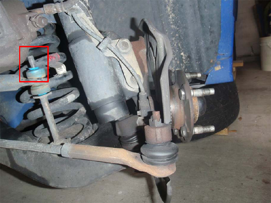
7. Continue with the driver’s side, and disconnect the sway bar end link nut. This nut is also 15mm in size but you will need a deep socket. If you just remove the top nut and top bushing, that is enough.
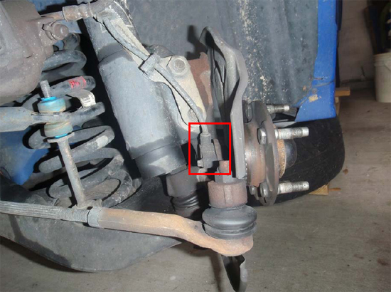
8. Finally, if your car has ABS, you need to remove the ABS sensor from the spindle using a ¼" 6-point socket. I used a 12-point, which also works fine. Once removed, lay the sensor on top of the caliper where it is out of the way.
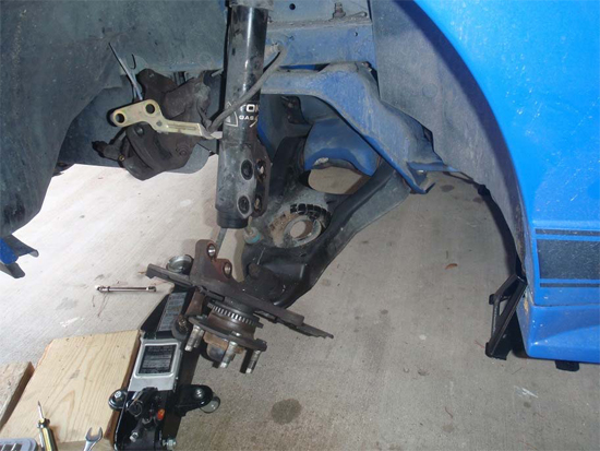
9. Now that all the front steering and suspension components have been detached, the next thing you want to do is SLOWLY lower the jack still holding the A-arm, until it no longer supports the A-arm. At this point, you should be able to pry your coilspring out of its place using a pry bar, and set it aside.
10. Next, repeat steps 4-9 on the passenger side of the car. The passenger side is the exact same process because all the components are identical.
11. Next, disconnect the steering shaft from the steering rack using a 14mm socket and extensions. This is easily accessed from behind the front, driver’s side wheel, looking up towards the front of the car.
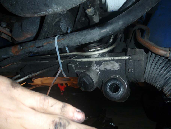
12. Now you need to disconnect the steering rack from the K-member and zip-tie it to the sway bar. There are two bolts holding the steering rack in place. You will need a ratchet with a short extension and an 18mm socket, and another ratchet with a 15mmsocket. Remove the bolts from each side and slide the steering rack off its mounts by pulling/rocking it towards the front of the car. It will be slow but eventually it will slide off. Zip-tie it to the sway bar, and make sure it is clear of the K-member. Refer to step 14 below for another view of the steering rack disconnected.
13. Next, disconnect and remove the K-member cross brace using a ratchet and a 15mm socket. This brace is behind the front wheels and goes under the front of the transmission. Removing it allows you to put a jack under the flat spot of the oil pan to support the motor.
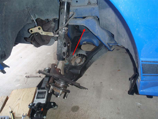
14. At this point, you should have the front steering and suspension components detached from both sides of the car. Next, you need to take one of your floor jacks and slide it in from the rear of the car, such that the handle is pointing towards the rear of the car and you are behind it. Grab the 2" x 8" and crawl under the car behind the jack. Line the jack up with the flat spot on the bottom of the oil pan, and sandwich the 2" x 8" between the flat spot and the oil pan. Raise the jack only enough to make sure it won’t move and check that the wood and the jack both clear the K-member vertically, as the wood and jack will be the only thing supporting the engine when you drop the K-member down and must remain in place. Use the following image as a reference for the jack and 2" x 8" position only, as you will not have the K-member removed yet.
15. After you are sure the jack is in the correct position, use a ratchet with extensions and a 22mm deep socket to remove the motor mount nut from each side of the car. The weight of the motor will keep it secured on the K-member with these nuts removed.
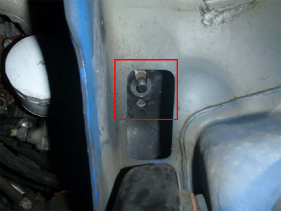
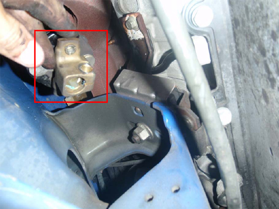
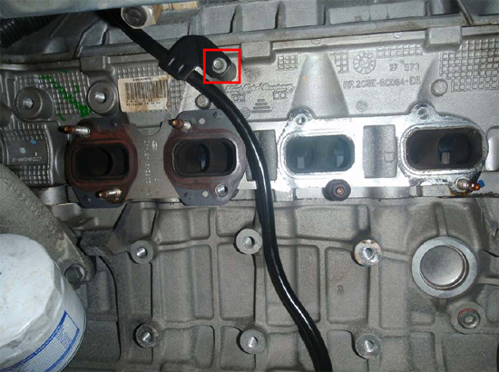
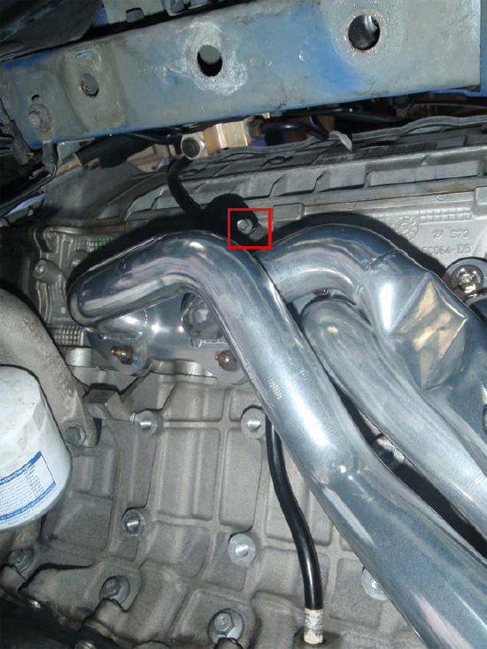
16. Beginning with this step, you will need at least one strong person to help you. The stock K-member is big and heavy, which makes it awkward to handle alone. Have your helper watch the motor mount bolt that goes through the K-member from one side, while you crawl back under the car and begin to raise the jack under the motor. Once they say the bolt (pictured above) is completely clear of the K-member, stop lifting the motor and crawl back out.
17. Now it is time to remove the K-member from the car. Take your second floor jack and place it under the K-member from the front of the car. You will most likely have to get this jack as close to the jack holding the motor as you can, without touching it. Make sure it is under the K-member and raise it up until it makes FIRM contact.
18. Next, remove the rear K-member support bolts (8 total, 4 per side). Using a ratchet and a 15mm socket, remove the 2 rear bolts on each side of the car – four in all. Then, using an 18mm socket, remove the 2 front bolts on each side of the car– four in all. The front bolts are located on either side of the spring perch.

19. The entire weight of the K-member should now be on the front jack. Lower the jack slowly so the K-member drops down. Then, you and your friend slide the K-member out towards the front of the car and set it aside. Be sure to set the A-arms on blocks of wood or something so that the brake dust shields do not get bent from the weight of the K-member.
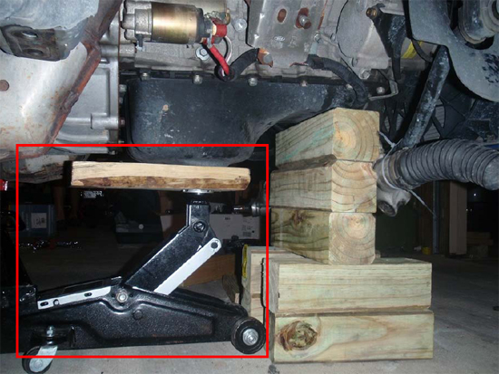
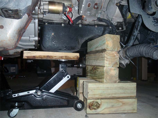
20. Now that the K-member is out of the way, I would put extra support under the shallow part of the oil pan in the form of stacked 4" x 4"s. The image below illustrates my method. This was just a precaution in case the hydraulic jack lost pressure. I would recommend you do the same, not only for peace of mind, but also as a way to keep track of the current motor height compared to where it started. This is important because you will have to raise and lower the motor throughout the installation to be able to access all of the header bolts.
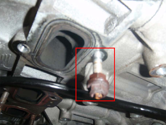
21. Now you need to disconnect and remove the stock h-pipe behind the headers. You will need a combination of 13mm and 15mm deep sockets and a 15mm box end wrench. It is helpful to have someone under the car with you to support the pipe while you get the last bolts off, but not necessary. Don’t forget to unhook the O2 sensors from their harnesses before trying to remove the pipe. Leave the actual sensors screwed into the stock h-pipe for now.
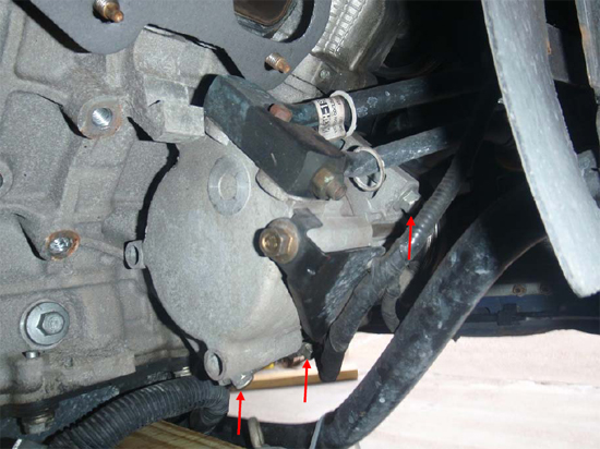
22. The next task is to remove the motor mounts from each side of the motor. This requires 13mm and 15mm deep sockets. The driver’s side mount has two ground straps attached to it while the passenger’s side mount has a cable harness attached to it. You must remove these by removing the 15mm nuts before you can remove the 13mm bolts that hold the motor mount to the block.
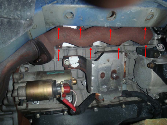
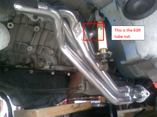
23. Now you’re ready to remove the stock manifolds. Using a 13mm deep socket and various extensions, you can remove all the nuts holding the manifolds in place. There are 8 bolts per side and some of the nuts may be stuck to the bolt such that the bolt comes out of the block with the nut. This is ok – do not worry about it. The driver’s side manifold also has the EGR tube attached to it. Remove this by loosening the nut with a large adjustable wrench.
24. Next remove the oil dipstick tube from the driver’s side of the motor using an 8mm socket to first disconnect the support bracket. Then push/pull the dipstick towards the sky and it will come out of the block.
25. Now you need to prepare the studs for the new headers. I would recommend using as many of the original studs as possible. They stand the least chance of damaging the delicate aluminum threads of the heads because it is much easier to thread a lock washer and nut on a rigid stud than try to thread a new bolt in through the header flange. I used 5 or 6 original studs with lock washers and 13mm nuts on each side and the rest were stage 8 locking header bolts. You are welcome to do whatever you like but the original studs will be the easiest and most painless. Here is an image of how to re-set a stud into the block. You just back two nuts against each other so that you have something to turn the stud into the block with. Once it is in place, turn the nuts away from each other, and back them both off the stud.
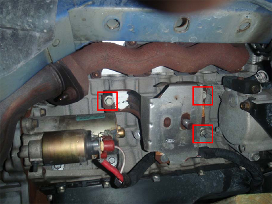
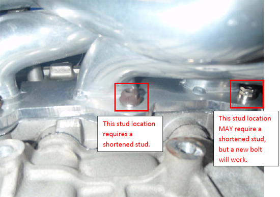
26. You do HAVE to re-use an original stud on one of the driver’s side flange holes. Not only that, you also shorten the stud length significantly. BBK’s design does not allow for a bolt to be threaded in from the outside. Fortunately, cutting a stock stud is a viable solution. The hole that requires this is the bottom, second from the rear, pictured below. I ended up using a new bolt on the rearmost hole next to it by chance, and did not check to see if a stud would work first. You may have to cut a stud for this hole as well if you want to use one there.
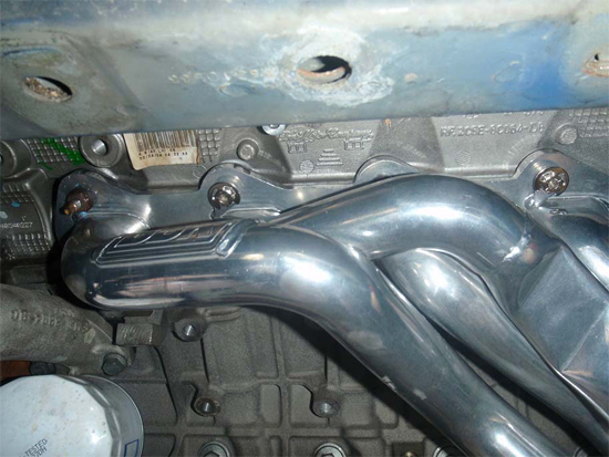
27. You are now ready to bolt the headers in place. Make sure you remove the original gaskets and put NEW gaskets in place before mating the header to the head. Then using a combination of 13mm deep sockets, a 13mm wrench and various extensions and swivels, tighten down each bolt/nut. If you are using a combination of original studs and new bolts, I would recommend tightening the nuts on the studs first, so that threading the new bolts through the flange will be a little easier. Be very careful though, as the aluminum threads are damaged VERY easily. If the bolt is tight before it gets very far, back it out and try to thread it again. Be sure each nut/bolt is tight to ensure a leak-free installation. Also, do not over-tighten them because, again, you are working with very delicate aluminum threads. The lock washers will prevent the nuts from backing out. For the driver’s side, I would recommend saving the EGR tube nut until after the header is tightened down completely. Below are a few pictures showing the driver’s side header installed.
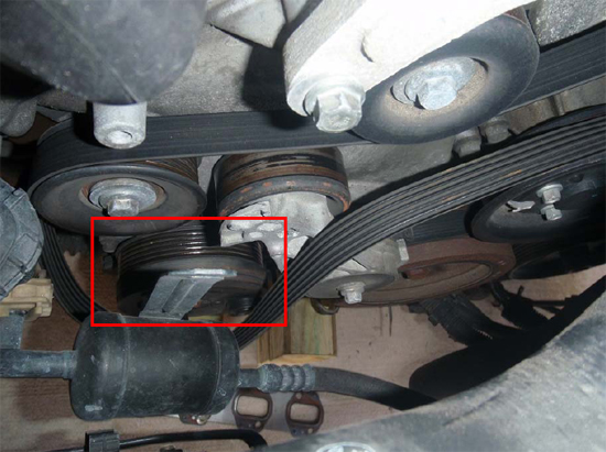
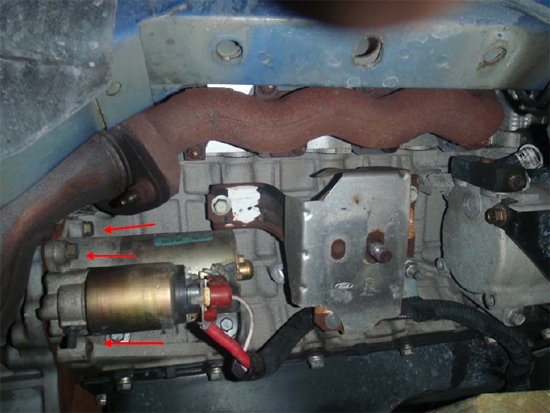
28. For the passenger’s side, you need to take the accessory belt off the AC compressor pulley and loosen the AC pulley in order to have room to get the header in place. You will also need to remove the starter in order to tighten the rear, lower nuts/bolts. None of the passenger side holes need special attention but the rear, upper bolts are, by far, the most frustrating part of this installation. You will need to lower the block as much as it will allow and use an open end wrench to slowly get to the rear, upper bolts. Again, take your time as each nut/bolt needs to be tight to ensure a leak-free installation but be sure not to over-tighten them.
29. Now it is time to reassemble everything. Tighten the AC compressor pulley and starter motor back into place on the passenger’s side and the EGR tube on the driver’s side if you have not already. Put the accessory belt back around the ACcompressor pulley.
30. Reinstall the dipstick between the 2nd and 3rd exhaust outlet.
31. Install the motor mounts to each side of the motor using the 13mm bolts, then reinstall the ground straps on the driver’s side and starter harness on the passenger’s side with the 15mm nuts.
32. At this point, you can go ahead and install the front O2 sensors into their respective sides on the headers. You will need the O2 extension wires to connect these sensors to their original harnesses.
33. Reinstall K-member in the reverse method that it was removed. It was really helpful to have two extra sets of hands and a jack during this step for me.
34. Once the K-member is bolted and torqued into place, lower the motor back onto the K-member making sure the motor mount bolts line up and go through the slot in the K-member. Once it is lowered onto the K-member and in the correct position, install the motor mount nuts using a 22mm deep socket.
35. Next install the steering rack back onto the K-member and then attach the steering shaft to the fitting on the steering rack.
36. Reinstall the G-load brace to the rear of the K-member under the headers and transmission. In my case, the brace was touching the header, so I had to put large washers between it and the K-member to make the brace sit a little lower.
37. Replace the coil spring and reinstall the suspension and steering components beginning with the last thing that was removed and continue backwards. The reinstall order should be: ABS sensor, sway bar end link bushing and nut, strut to spindle and ABS bracket, tie-rod end, and rotor and brake caliper. Refer to steps 4-9 for images and tools required. Be sure to re-bend the cotter pin once you slide it through the castle nut of the tie-rod end.
38. Now repeat step 37 on the passenger side of the car. The passenger side is the exact same process because all the components are identical.
39. Now you can go ahead and install your midpipe. Follow whatever instructions are provided and make sure to remember to transfer the rear O2 sensors from the stock h-pipe to the new midpipe and connect them to the harnesses.
40. Finally, put the wheels back on the car, tighten the lug nuts, lower the car, and torque the lug nuts down. Take it for a spin and listen for leaks. If you took your time and used quality gaskets you should be leak free and good-to-go! Congrats!
Installation instructions provided by AmericanMuscle customer Jon David Johnson 1.26.10
