FREE 1 to 3-Day Delivery on Orders $149+ Details
How to Install Borla 1-3/4 in. Long Tube Headers w/ X-Pipe (05-10 GT) on your Ford Mustang
Tools Required
- 3/8” Drive Ratchet
- 3/8” Drive Extension 3”
- 15mm Socket
- Pry Bar
- Flat blade screwdriver
- Spray Lubricant
Precision manufactured using aircraft quality T-304 stainless steel; this system is designed to endure years of heavy use. Installing a Borla Performance Exhaust System on your vehicle will eliminate the restrictive design of the stock exhaust, allowing your engine to discharge exhaust gas easier. The result is more horsepower and torque, longer engine life, and a distinctive throaty growl- all this, with easy bolt-on installation. These installation instructions have been written to help you in the installation of your Borla Performance Exhaust System. Please read it completely before installing your system.
Thank you for purchasing a Borla Performance Stainless Steel Long Tube Header System.
This Borla Performance Stainless Steel Long Tube Header System (PN 17237) has been designed for 2005-2006 Ford Mustang GT equipped with a 4.6L V-8 engine and automatic or manual transmissions.
FOR RACING USE ONLY. NOT LEGAL FOR USE ON PUBLIC ROADS.
Borla Performance Industries recommends that an exhaust shop or professional after market parts installer, who has all the necessary equipment, tools and experienced personnel needed for proper installation, should perform the installation of this system. However, if you decide to perform the installation, we recommend someone should help you. Ensure the installer uses all under car safety precautions including eye protection.
Please take time to read and understand the following…
By installing your Borla Performance Exhaust System, you indicate that you have read this document and you agree with the terms stated below.
It is the responsibility of the purchaser to follow all installation instruction guidelines and safety procedures supplied with your Borla Performance Exhaust System
Borla Performance Industries assumes no responsibility for damages occurring from misuse, abuse, improper installation, improper operation, lack of responsible care, or all previously stated reasons resulting from incompatibility with other manufacturer’s products and/or systems.
Included with your Borla Performance Exhaust System is a warranty card. Please read it carefully before you begin any work on your vehicle. If you should have any questions regarding our warranty policy, installation, or any other matter pertaining to your new Borla Performance Exhaust System, please give us a call at the number provided on the warranty card.
Borla Performance Stainless Steel Long Tube Header System Bill of Materials
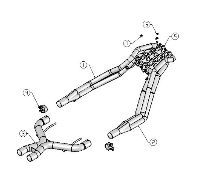
1. Left header assembly
2. Right header assembly
3. X pipe assembly
4. 2.50” clamp (qty 2)
5. Header gasket (qty 2)
6. Stage 8 locking header bolt kit
7. Dipstick spacer
Caution!!! Never work on a hot exhaust system. Serious injury in the form of burns can result If the vehicle has been in use and the exhaust system is hot, allow vehicle to cool for at least 1 hour. Always wear eye protection when working under any vehicle.
Note: It is our recommendation that you use a hoist or hydraulic lift to facilitate the installation of your new Borla Performance Header Exhaust System.
Taking all under car safety precautions, lift the vehicle using a hoist or hydraulic lift. Once this has been done, you may begin the removal of your old exhaust system from your vehicle.
Note: Before removing the original exhaust system from your vehicle, please compare the parts you have received with the bill of materials provided on the previous page to assure that you have all the parts necessary for the installation of your new Borla Performance Header Exhaust System.
Original Exhaust System Removal
Note: With a used vehicle, we suggest a penetrating spray lubricant to be applied liberally to all exhaust fasteners and allowing a significant period of time for the chemical to lubricate the threads before attempting to disassemble.
1. Disconnect and remove the battery from the vehicle.
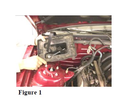
2. Unbolt and remove the battery tray from the vehicle as shown in figure 1.
3. Remove spark plug wires from spark plugs.
4. Remove the serpentine belt from the vehicle as recommended by the vehicle manufacturer.
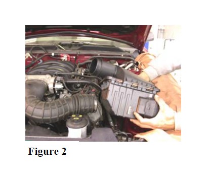
5. Remove the air filter according to the vehicle manual and unbolt the air filter housing. disconnect the sensor, loosen the clamp securing the intake tube to the housing and remove the filter housing from the vehicle as shown in figure 2.
6. Unbolt and remove the dipstick from the driver side of engine.
7. Carefully lift the vehicle.
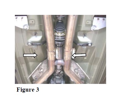
8. Loosen the clamps shown in figure 3 located just behind the h-pipe.
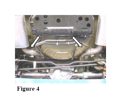
9. Loosen the clamps shown in figure 4 located just in front of each muffler assembly.
Note: With a used vehicle, we suggest a penetrating spray lubricant to be applied liberally to all exhaust fasteners and allowing a significant period of time for the chemical to lubricate the threads before attempting to disassemble.
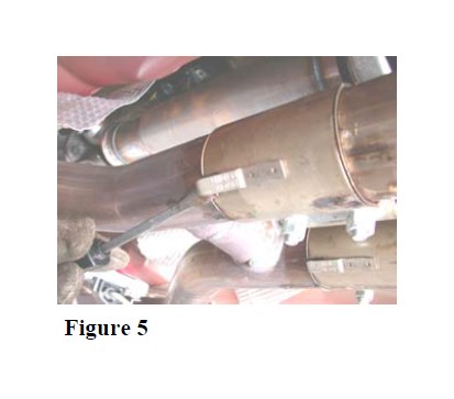
1. Beginning with the left (driver) side, using a flat blade screwdriver, pull the clip as shown in figure 5 to disengage it from the pipe.
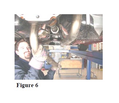
2. Remove the left (driver) side over axle pipe shown in figure 6 by removing the front of the pipe from the h pipe assembly first then slide it out of the muffler assembly.
3. Repeat steps 1 and 2 for the removal of the right side over axle pipe.
4. Lubricate all hanger and rubber isolators.
5. Disconnect all of the Oxygen sensor harnesses.
6. Disconnect the sensor located on the right (passenger) side of the oil pan.
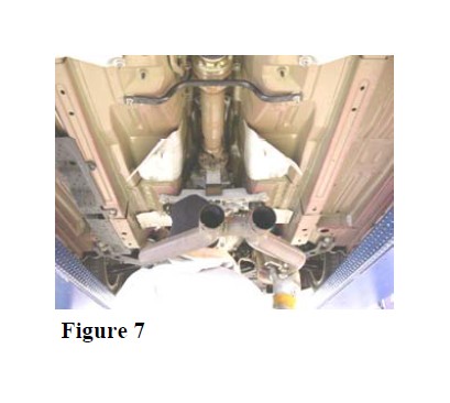
7. Using a muffler stand or an additional person to hold the catalytic converter/h pipe assembly up into position, unbolt the flanges located just behind the catalytic converters, remove the hangers from the rubber isolators and remove the catalytic converter/h pipe assembly from the vehicle as shown in figure 7.
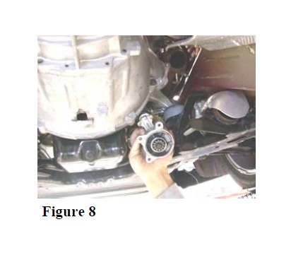
8. Disconnect the wiring, unbolt and set aside the starter as shown in figure 8.
9. Unbolt the steering shaft.
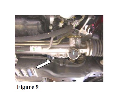
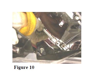
10. Unbolt the rack and pinion and slide it forward as shown in figure 9, just enough to allow the steering shaft to be removed as shown in figure 10.
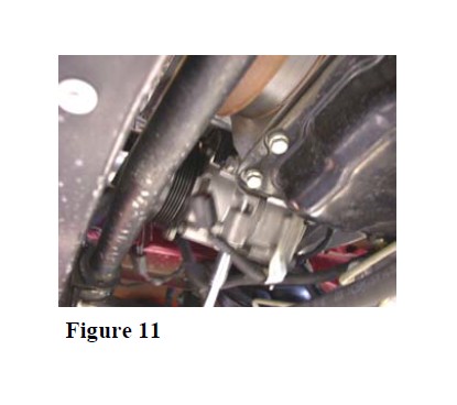
11. Without disconnecting any hoses, unbolt the air conditioning compressor shown in figure 11. Disconnect the electrical connection and move it forward to allow you clearance for the removal of the factory manifolds and installation of you long tube headers.
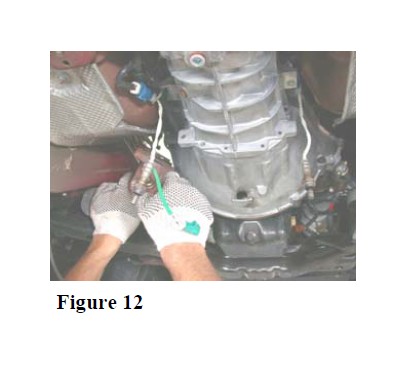
12. From under the vehicle, unbolt and remove the left (driver side) factory exhaust manifold as shown in figure 12.
13. Repeat step 11 for the removal of the right (passenger) side factory exhaust manifold.
14. Carefully remove each Oxygen sensor from the factory exhaust manifolds and install them into the upper bungs of your new long tube headers.
Warning: Use extreme caution during installation. Torque all fasteners according to manufacturer’s torque values and tightening sequence. DO NOT use air impact tools to tighten fasteners on Borla Performance Exhaust Systems. Use of such tools may result in bent flanges or gasket contact areas leading to exhaust leaks.
Borla Performance Stainless Steel Long TubeHeader System Installation
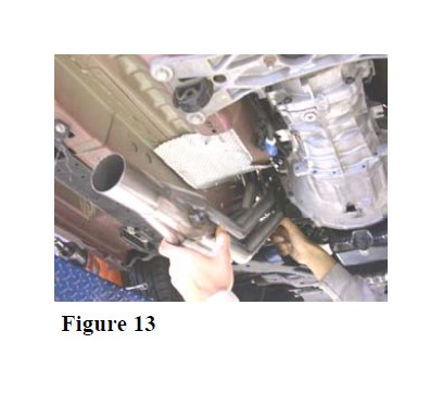
1. Using the gaskets and the Stage 8 locking header bolts supplied, place the left (driver) side header into position as shown in figure 13. Tighten the bolts to 13-23 ft. lbs.
2. Repeat step 1 for the installation of the right (passenger) side header.
3. Install the air conditioning compressor opposite of removal. Reconnect the electrical connection.
4. Slide the rack and pinion back into position while guiding the steering shaft. Install and tighten the bolt securing the rack and pinion and install and tighten the bolt for the steering shaft.
5. Install the starter opposite of removal.
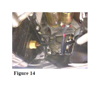
6. Reconnect the sensor shown in figure 14 located on the right (passenger) side of oil pan.
7. Install the Oxygen sensors into the lower bungs of your new long tube headers.
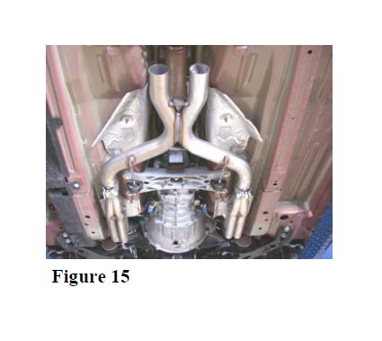
8. Place a clamp over the expanded ends of the X pipe assembly and set it up into position as shown in figure 15 installing the hangers into the rubber isolators.
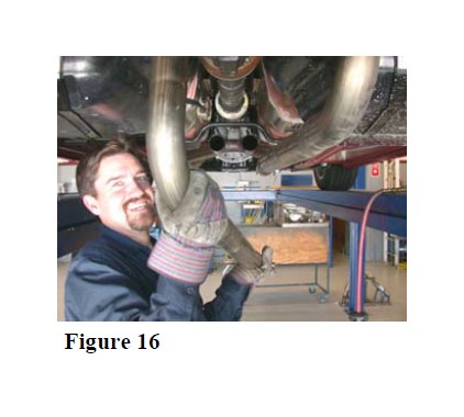
9. Place the left (driver) side over axle pipe into position as shown in figure 16 by first installing the rear portion into the muffler assembly than the front portion onto the X pipe assembly.
10. Repeat step 9 for the installation of the right (passenger) side over axle pipe.
11. Check your exhaust system for proper clearance under the vehicle.
12. Once position has been determined to be correct, tighten the Accuseal ™ clamps to 32-35 ft. lbs.
13. Carefully lower the vehicle.
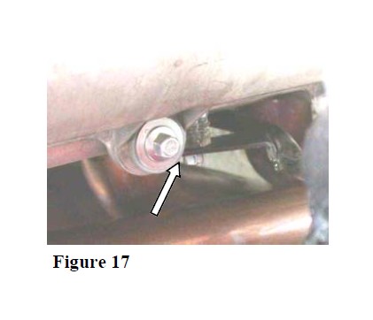
14. Install the dipstick using the original hardware and the spacer provided as shown in figure 17.
15. Install the air filter housing opposite of removal. Install the air filter into the housing according to the vehicle manual.
16. Install the serpentine belt, spark plug wires, battery tray and battery opposite of removal.
17. Before starting your vehicle, make sure to check all wires, hoses, brake lines, body parts and tires for safe clearance from the exhaust system.
18. Start vehicle and check for any leaks. If any leaks are found, determine cause (such as loose or incorrectly positioned clamp) and repair as necessary. Allow the exhaust to reach normal operating temperature and then turn engine off.
19. Allow the exhaust to completely cool and re-torque all fasteners. Install the anti rotation clips followed by the locking clips included with your Stage 8 locking header bolts.
Note: When you first start your vehicle after the installation of your new Borla Performance Exhaust System, there may be some smoke and fumes coming from the system. This is a protective oil based coating used in the manufacturing of mandrel bent performance exhaust tubing. This is not a problem and will disappear within a very short period of time after the exhaust has reached normal operating temperatures.