 FREE 1 to 3-Day Delivery on Orders $149+ Details
How to Install a Modern Billet Polished Billet Shift Knob w/ Running Pony Logo on your 1979-2004 Man
Tools Required: None Required
Install Time: 15 minutes
Instructions:
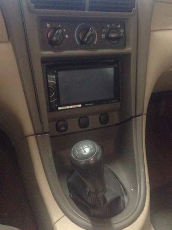
1. Locate your old shift knob.
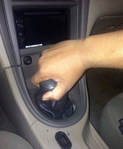
2. Turn old shift knob counter clockwise until it spins off.
(NOTE: I found it took 19 full turns to come off)
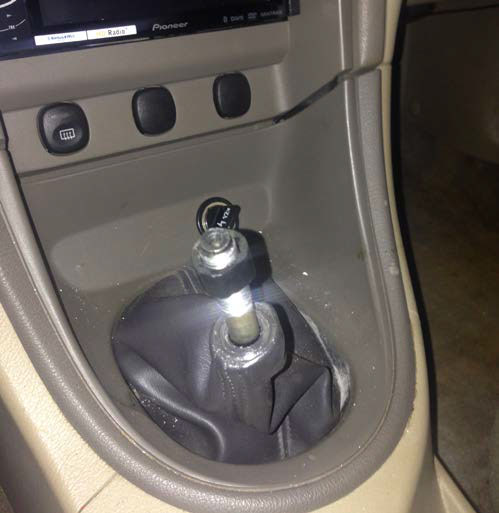
3. Once off, you may notice a hard plastic piece still remains on the shifter. DO NOT PANIC! Just give plastic piece a few more counter clockwise turns and it will come off.
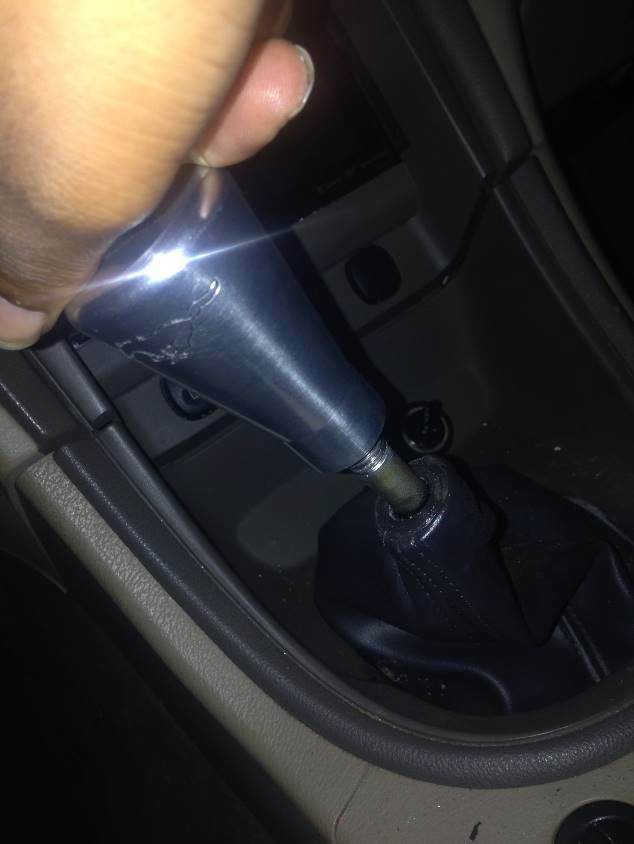
4. Shifter will now be naked.
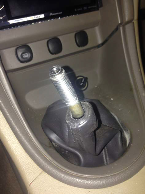
5. Take new Polished Billet Shift Knob and align with shifter – male end to female end – begin turning clockwise.
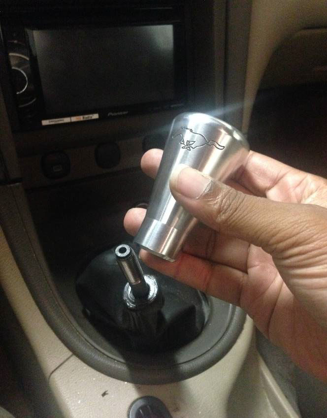
6. Continue to turn clockwise until you cannot turn anymore, usually 19-20 rotations.
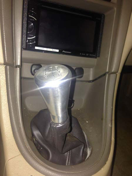
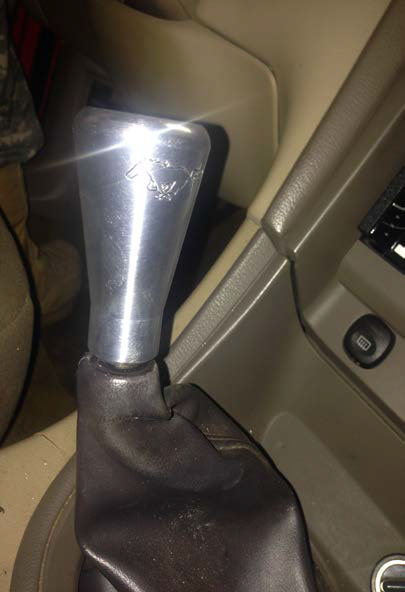
7. Congratulations! You are complete. Admire your new shift knob!
Installation Instruction Written by AmericanMuscle Customer Carlos Graves 4/8/2014
