FREE 1 to 3-Day Delivery on Orders $149+ Details
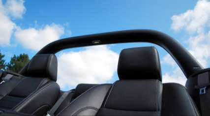
How to Install a Classic Design Concepts Convertible Lightbar on your 2005-2013 GT, V6 and GT500 Mu
Installation Time
4 hours
Tools Required
- 3/8" Drive Ratchet
- 3/8" Drive 3" Extension
- 3/8" Drive 10mm Socket
- 3/8" Drive 13mm Socket
- T-50 Torx Bit
- 1/4" Allen Wrench
- 3/16" Allen Wrench
- 1/2" Wrench
- Wire Cutter/Stripper
- Drill Motor
- 1/8" Drill Bit
- 5/16" Drill Bit
- 2" Hole Saw
- Trim Tool (Fork Tool)
- Electrical Tape
- Center Punch
- Hammer
- Wire Crimper

Note: Read installation instructions before starting.
Component List:
1 – LightBar Part #110000
1 – Driver Side Bracket w/Set Screw Part #115003
1 – Passenger Side Bracket w/Set Screw Part #115004
4 – Button Head Screw Part #117000
4 – Flange Nut Part #117001
2 – 4” Zip-Ties Part #116053
1 – CDC LightBar Wiring Harness Part #05001
1 – Light Blue T-Tap Connector (2010-13 Only) Part #182003
1 – Red T-Tap Connector (2010-13 Only) Part #117032
2 – 6” Velcro Strap Part #950009
Tools Required:
⅜” Drive Ratchet
Drill Motor
⅜” Drive 3” Extension
⅛” Drill Bit
⅜” Drive 10mm Socket
5/16” Drill Bit
⅜” Drive 13mm Socket
2” Hole Saw
T-50 Torx Bit
Trim Tool (Fork Tool)
¼” Allen Wrench
Electrical Tape
3/16” Allen Wrench
Center Punch
½” Wrench
Hammer
Wire Cutter/Stripper
Wire Crimper
The Classic LightBar is NOT intended to provide
protection in the event of a rollover.
The Classic LightBar is Patented: All rights reserved by Classic Design Concepts
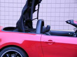
1. Remove Back Seat:
A) Locate the retainers securing the seat bottom into the vehicle, approximately 10 inches from the end of the cushion, either side. Use your thumb to push in retainer release tab. Lift the seat up to remove.
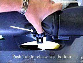
Figure 1
B) Remove the two 13mm screws securing the seat back, located on each lower corner. Lift seat upward to release seat back from brackets at the top. You can carefully prop the seat back under the retracted top (see Figure 2 below), use caution if choosing this method not to damage or scratch the vinyl of the seat. You can remove the seat from the vehicle completely by disengaging the flanges securing the top of the rear seat to the fabric of the convertible top well (see Figure 3 below).
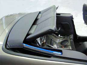
Figure 2
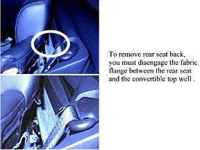
Figure 3
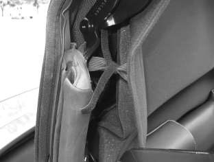
2. Remove Quarter Trim Panels:
A) Grip the Quarter Trim Panel Cap at the shoulder strap opening and lift up to dislodge the retaining clips.
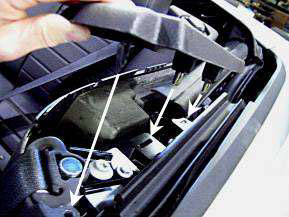
Figure 4
B) The inside plastic Quarter Trim Panels are two-piece panels. Remove the upper portion of the Quarter Trim Panel from the vehicle; it is not necessary to remove the lower portion. Pull the forward edge of the trim Panel over the pinch weld in the doorjamb, then run your fingers across the seam between the two parts, separating the panels.
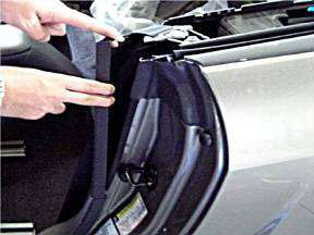
Figure 5
C) Use a Door Trim Tool (Fork Tool) to dislodge the pushpin retainer at the rear edge of the Trim Panel approximately 4” down from the top, pry Trim Panel toward the outside of car to release retainer.
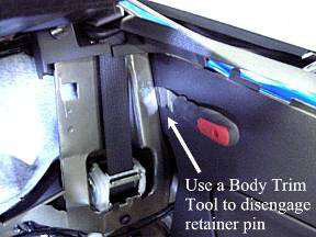
Figure 6
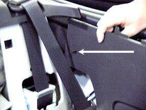
Figure 7
3. Install Light Bar Brackets:
A) Remove the shoulder belt guide retaining bolt with a T-50 Torx Bit. Remove the 10mm bolt directly behind the shoulder belt guide.
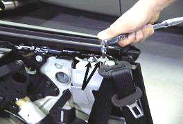
Figure 8
B) Install the LightBar Bracket to the vehicle using the factory bolts removed in the above step.
Note: Factory Seatbelt Bolts are intended only as locators for the LightBar Brackets, NOT to secure the Brackets. Torque seatbelt guide bolt (T-50 Torx) to 30 lb-ft. It is imperative that the shoulder strap guide bolt spacer fit inside the clearance hole of the LightBar Bracket so that the seat belt functions properly and the LightBar Bracket fits properly.
C) With the LightBar Bracket in place and secured by the 10mm bolt and the shoulder strap bolt reinstalled, center punch through the two Bracket attachment holes. Drill ⅛” pilot holes through Bracket hole into sheet metal. Enlarge pilot holes to 5/16”.
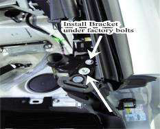
Figure 9
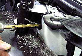
Figure 10
Note: It is very important that you protect the seat belt and the shoulder strap retractor from the cutting debris that is created during the drilling process. We recommend using a magnet or drop cloth to catch the debris.
D) Install the Button Head Screws through the Bracket, place nuts on the inside of the body channel, securing Bracket to the vehicle. Tighten Button Head Screws.
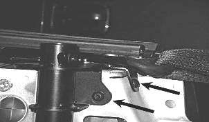
Figure 11
E) Repeat installation steps for Light Bar bracket on opposite side of car.
3. Wiring LightBar LED: YEAR SPECIFIC- read ALL instructions before beginning!
A) All Years: Route the plastic Connector end of CDC LightBar Wiring Harness #05001 behind speaker and up through the LightBar Bracket tube. Let the Connector end of Harness hang out of the top of LightBar Bracket, leaving approximately 4” slack.
NOTE: Secure all wires away from the moving components of the Convertible Top mechanism.
B) LIGHTBAR GROUND (Black) WIRE
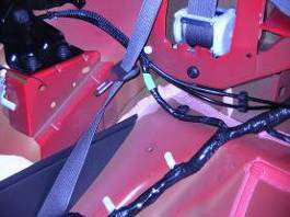
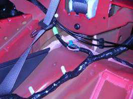
All Years: Locate the plug behind the passenger side quarter trim panel, to the rear of stereo speaker. Remove connector from the sheet metal by dislodging the retainer clip. (Figure 12, below)
Locate the factory White Wire with Purple Stripe (solid White on some 2011 cars) within the connector. From the back of the connector (no need to disconnect/separate connector halves), push the metal terminal of the LightBar Wiring Harness Black wire into the same connector opening along side the metal terminal of the White or White/Purple wire. Secure the Black CDC wire to the factory harness with a 4” Zip Tie (CDC #116053). Place Zip Tie immediately behind the shrink wrap on the Black Wire Pin. Tug Black wire to verify that Zip Tie and Pin are secured. Wrapping the CDC wire to the factory wires with electrical tape can provide additional support.
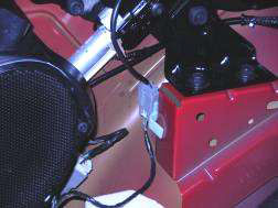
Figure 12
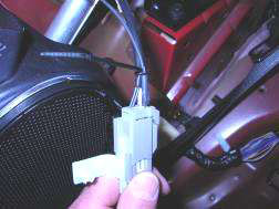
Figure 13
C) LIGHTBAR POSITIVE (Red) WIRE
2005-2009 Models:
Route the remaining red LightBar Harness wire into passenger side of trunk, following existing wire harnesses next to convertible pump. Locate the wire harness connector on the passenger side of the trunk, attached to the under-side of the “package tray” area. The connector is located along the wire harness that feeds the trunk lid. Remove connector from the sheet metal by dislodging the retainer clip to aid in LightBar wire installation. Locate the factory Tan Wire with Blue Stripe within the connector. From the backside of the connector, push the metal terminal of the LightBar Wiring Harness Red wire into the same connector opening along side of the metal terminal of the Tan/Blue wire. Secure the Red CDC wire to the factory harness with a 4” Zip Tie. Place Zip Tie immediately behind the shrink wrap on the Red Wire Pin. Tug Red wire to verify that Zip Tie and Pin are secured. Wrapping the CDC wire to the factory wires with electrical tape may provide additional support.
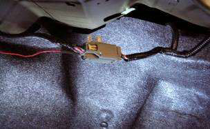
Figure 14
2010-2013 Models:
Locate the wire harness on the passenger side leading to the trunk. There is a branch coming from the main bundle that runs outward, this is where you will find the 2010 positive trigger wire. Attach the Red T-Tap Connector (CDC #117032) to the Yellow w/Brown stripe wire in 2010 Mustangs. In 2011 Mustangs, use Yellow w/Silver stripe. Cut the spade terminal off of the CDC Harness Red wire, strip end, and crimp on the Light Blue Connector (CDC #182003). Route red wire behind quarter trim panel and plug Red wire w/Light Blue Connector into the Red T-Tap.
D) Temporarily plug LightBar into Harness and press the brake pedal to verify proper function of LED. If LED doesn’t illuminate when brake pedal is depressed, check your connections at both connections. When verification is complete unplug the Light Bar from the LightBar Vehicle Harness and set aside.
E) Reinstall the upper portion of the Quarter Trim Panels on both sides.
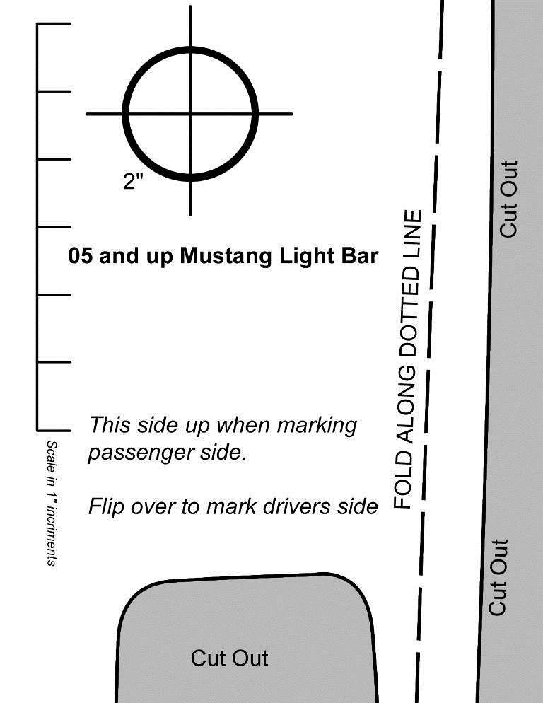
5. Cutting holes in Quarter Trim Panel Caps:
A) Cutout the Template (last page of instructions) and place on the Passenger Side Trim Panel Cap and align as directed on the Template. Center punch the 2” hole center point, remove the template and drill an ⅛” pilot hole. Follow in the pilot hole with a 2” Hole Saw.
B) Flip Template over and place on the Driver Side Trim Panel Cap and repeat the above steps for marking and drilling the 2” hole.
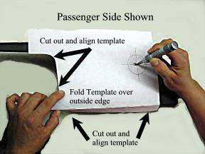
Figure 16
6. Reinstall Quarter Trim Panel Caps:
A) Install the Trim Panel Caps onto their respective sides and verify that the 2” holes drilled in step #4 do not obstruct the LightBar Bracket receiver tube. If the receiver tube is blocked, trim the Cap as necessary to achieve an unobstructed path for the LightBar to pass through. The Connector end of the CDC LightBar Harness MUST extend out of the Bracket to allow for connection to the Bar (Figure 17).
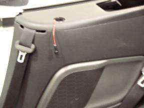
Figure 17
7. Installation of Classic LightBar:
A) Plug the Connector from the LED into the CDC Vehicle Harness installed in the previous steps. Step on brake pedal to verify proper LED function. If LED doesn’t illuminate when the brake pedal is depressed, check your connections at the truck connector then the connector behind the Trim Panel. Push wire down through the LightBar Bracket receiver tube while lowering the LightBar ends into the Mounting Brackets.
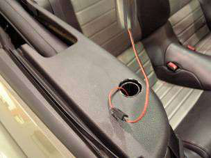
Figure 18
B) Lower Classic LightBar evenly into Mounting Brackets. Lower Bar down to the tops of Trim Panel Caps. With the bottom of the LightBar flat on the surface of the trim panel Caps; tighten the LightBar Bracket Set Screw.
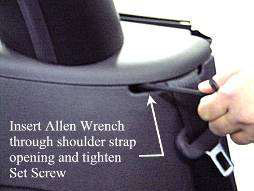
Figure 19
8. Reinstall your back seat:
A) Reinstall by reversing step 1.
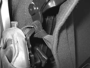
9. Clearance Convertible Top:
A) Cycle the convertible Top to the half-way point. Locate the elastic band that secures the top to the frame at the forward end of the rear window seal.
B) Use the 6” Velcro straps (CDC # 950009) to draw the elastic band tight. Cross the Velcro Strap around the elastic band. Route the top leg of the Velcro Strap behind the frame. IT IS IMPORTANT THAT THE TOP LEG GO UNDER THE FRAME!
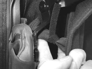
C) Wrap the top leg around frame and secure Velcro Strap to the frame with the bottom leg of the Velcro Strap, as shown.
Thank you for choosing Classic Design Concepts for your restyling needs.
If you have any questions or concerns regarding installation please contact
[email protected] or call 866-624-7997.