 FREE 1 to 3-Day Delivery on Orders $149+ Details
How to Install a Classic Design Concepts Shaker System on your 2011-2013 Mustang GT
Installation Time
3 hours
Tools Required
- Masking Tape
- Fork Tool
- Straight Edge
- Scissors
- Center Punch
- 3/32" Drill
- 1/8" Pilot Drill Bit
- 3/8" Drill
- 3" Hole Saw
- Drill Motor
- Saw with metal blade (for cutting hood)
- Utility Knife (for cutting hood blanket)
- Razor Blade
- Eye Protection
- Rivet Gun
- 10mm Socket ¼" Drive
- 8mm Socket ¼" Drive
- 11 mm Socket ¼" Drive
- ¼" Drive 6" extension
- ¼" Drive Ratchet
- Tape Measure
- Removable Thread Locker
Installation
Component Check List:
| Shaker Assembly: | Part # |
|---|---|
| 1 - Aluminum Shaker Scoop | 183020 |
| 1 – Upper Air Box | 1111-3301-01 |
| 1 – Water Management Tray | 1111-0500-01 |
| 1 - Lower Air Box | 1111-3300-01 |
| 4 – M6-1.0 x 60mm Bolt | 30009 |
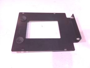
| 1 – Front Mounting Bracket | 1111-3500-01 |
| A. 4 - M6-1.0 x 22mm Bolt | 410109 |
| B. 2 - M6 Washer | 183005 |
| 1 – Rear Mounting Bracket | 1111-3501-01 |
| A. 2 – Ball Studs | 183001 |
| B. 2 – M6 – 1.0 Nut | 183034 |
| C. 2 – M6 Washer | 183005 |
| 1 – Manifold Bracket | 1111-3502-01 |
| A. 2 – Ball Stud Receiver | 183000 |
| B. M6-1.0 Nutsert | 50007 |
Separate Components:
- 1 – Upper Trim Ring 1095-2106-01
- 1 – Lower Trim Ring 1095-2105-01
- 1 – Upper Air Tube 1111-3303-01
- 1 - Lower Air Tube 1111-3302-01
- 1 – Air Tube Adapter 0511-2102-01
- 1 - Drain Tube 115058
- 1 – Hood Template
- 1 – Airbox Template
- 1 – Installation Instructions
Hardware Kit: 1011-6500-01
- M6-1.0 x 30mm Threaded Coupler 1111-3505-01
- M6-1.0 x 33mm Threaded Coupler 1111-3506-01
- 4 - M6-1.0 x 22mm Bolt 410109
- 1 - ¼” 3M Acrylic Bonding Tape 950015
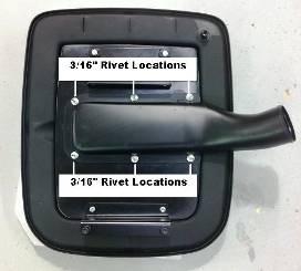
- 6 – 3/16” Rivets 182016
- 4 – 3/32” Black Rivets 183011
- 2 – Alcohol Packs 950006
- 2 – Adhesion Promoter Packs 950007
Note: Read installation instructions before starting. Test fit components before painting. The molded Shaker Hood Trim Ring is UV Stable, ABS Plastic and does not require paint. If you chose to paint the Shaker Hood Trim Ring, have your Trim Ring painted by a professional automotive painting facility to ensure the quality of your vehicle and the product. We recommend that paint-curing temperature not exceed 180F.
Preparing:
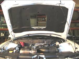
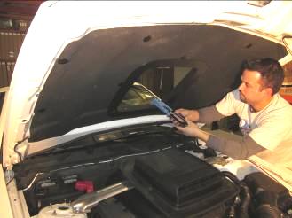
1. Raise Hood and remove under hood blanket, use a fork tool to remove pushpin fasteners. Set hood blanket aside.
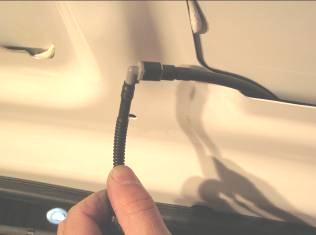
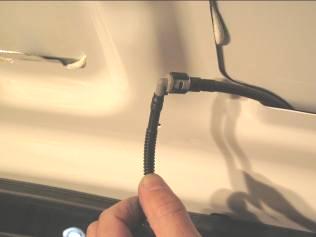
2. Remove the center clips that secure windshield washer hose to bottom side of hood and discard.
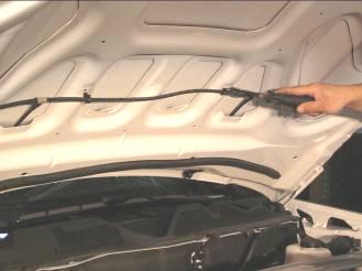
3. Disconnect them at the “T” (passenger side) and elbow (driver side). Hint: Twist the black plastic retainer counter clockwise to release.
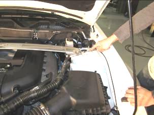
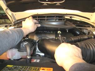
4. Remove the 4 (13mm) nuts that secure the factory Strut Tower Brace (if equipped).

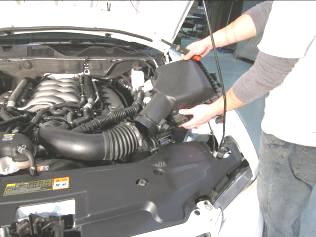
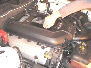
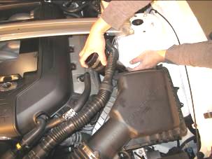
5. Remove Engine Cover. Engine cover is held down with 4 ball studs, firmly grasp cover and lift to remove.
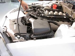
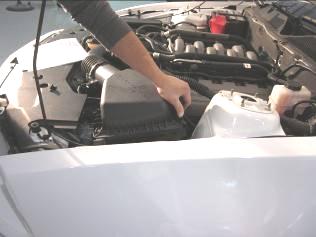
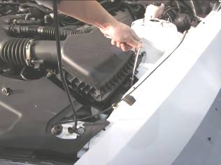
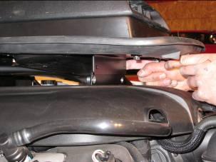
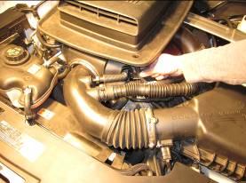
6. Remove Air Box. Release the 2 clips that secure the lid. Loosen the clamp (8mm); disconnect the Mass Air Flow Sensor Connector. Remove the sound tube mount from airbox, and finally remove the 10mm bolt near the fender.
7. Close hood and mask off area where Shaker Opening will be cut out. Also add tape along the edge of the hood.

8. Measure and mark centerline on the hood. Measure 7” and 38” from the rear corners of the hood on both driver and passenger side of the hood. Next, measure from the outside of the hood to mark the centerline. Hint: From the 7” mark, it is approximately 29-7/8” to the center. From the 38” mark, it is approximately 28-9/16” to the center. These measurements are intended as reference only. Note: Double Check Your Measurements, It is very important that the centerline of hood is measured accurately. Now that you are confident of your measurements, use a straight edge to draw the centerline on the hood.
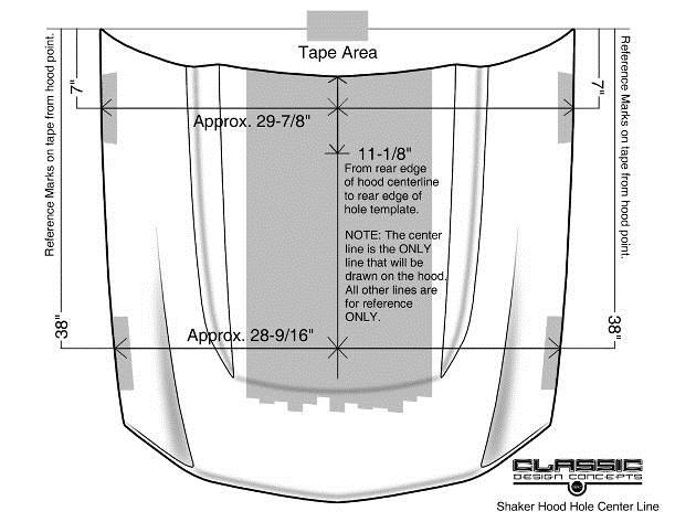
9. On the centerline, measure 11⅛” from rear of the hood and mark a line on the tape, intersecting the centerline. This will align with the rear cutout line of the Shaker Cutout Template.
Note: To aid in locating the Template, cut out a small triangle at the intersection of the centerline and the rear of the Shaker cutout hole (on template) to locate the 11-1/8” line mark.
10. Place Hood Cut Out Template on hood. Align the centerline of the hood to the centerline of the template. Align the rear line of the template to the 11⅛” mark on the hood. Tape template securely to top of hood.
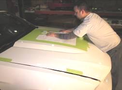
11. With a sharp razor blade or X-Acto Knife cut through template and tape, scoring the paint on the hood. Scoring the paint on the hood will help reduce the chance of paint flake during the cutting process.


12. Remove Template from hood and discard. Peel tape from center of Shaker opening, leaving an outline of Shaker opening.

Note: As a precautionary measure, add a second layer of tape around opening to reduce the risk of scratching the hood. During the drilling and cutting process, elevate the hood far enough to ensure no damage will occur to engine components. Place a blanket over engine to catch shavings.

13. Drill a starter hole in the Shaker opening large enough for the blade of your saw to pass through.
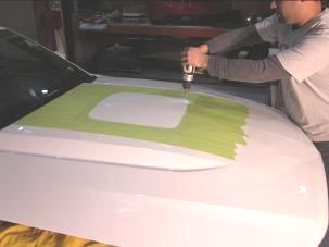
14. Cut Shaker opening. Be patient and pay attention to your blade, if it appears to be getting clogged, stop cutting and replace blade.

Hint: To help reduce excessive vibration, stop cutting at the half way point and place masking tape over the cut line to support the center, or place paints sticks under the corners.
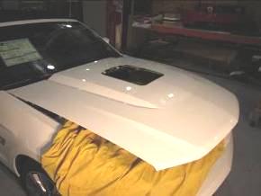
15. Remove tape from hood. Clean area of hood around the cut opening with Isopropyl (rubbing) Alcohol where Upper Trim Ring will be placed. It is imperative that all wax be removed from the tape contact area for proper adhesion of Trim Ring.
16. Raise and prop hood.
17. Temporarily reinstall hood blanket to bottom of hood using original fasteners.
18. Close Hood and trace hood cutout onto the hood blanket (a white grease pencil works best). Raise hood and remove hood blanket.

19. Cut opening in Hood Blanket with a sharp blade.
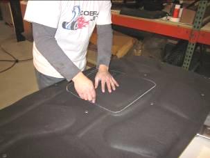
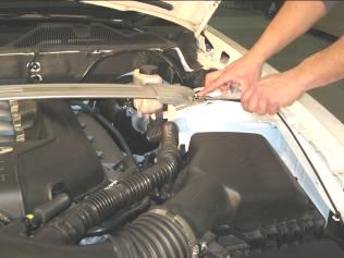
20. Reconnect squirter hoses, and reinstall hood blanket with factory retainers.
Drill 3” Hole hole in air box:
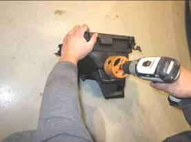
1. Cut out the provided paper Aibox template and place on Aibox to locate the center point. Mark the center point with center punch (or similar).
2. Remove the paper template and carefully drill the hole with a 3” hole saw.
3. Debur the hole and snap the lower airtube in to place.

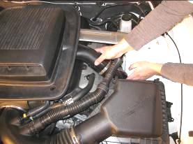
4. Reinstall the airbox to its original location.
5. Re-install Air Filter into factory air box.
6. Re-install air filter housing lid to factory air box and snap locking tabs into place. Reconnect Mass Air Flow Sensor, and sound tube.
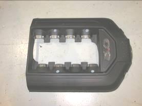
Drill holes in Engine Cover:
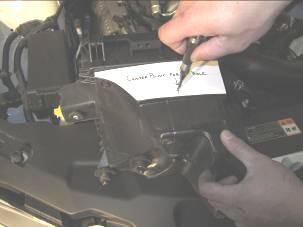
1. Using the picture below as reference, measure from the back edge of the engine cover and mark the 4 locations to be drilled. Passenger side = 7-1/8” and 15”. Driver side = 6-1/16” and 13-15/16”.
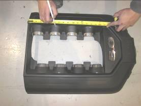
2. Drill the 4 locations. Start with pilot hole, then enlarge with ¾” to 1” step bit or hole saw. Note: You will start your hole approximately 1/8” from the angled wall of the engine cover. When you drill the ¾” to 1” hole, you will be drilling the flat surface and the angled surface.
3. Install the 4 threaded couplers on the 4 fuel rail studs. Torque to 10.4 Nm or 7.8 lb-ft. Note: There are 2 different length couplers, 30mm and 33mm. The 30mm are to be used on the forward studs and the 33mm studs are to be used on the rear studs. Use a removable thread locker and torque to 10 Nm or 7.8 ft. lbs. DO NOT over tighten.
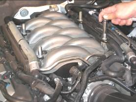
4. Reinstall the engine cover. The couplers are now visible through the drilled holes.
5. Separate the Shaker from the Manifold Bracket. Remove the (2) bolts that secure the front of the Shaker to the Manifold Bracket, and pull the Shaker away from the bracket. The Ball Studs will disengage by pulling.
6. Install the Manifold Bracket. Place bracket on top of the threaded couplers and fasten with the M6-1.0 x 22mm bolts. Note: The mounting holes are slotted in the Manifold Bracket. Center the mounting bolts in the slots to maximize adjustment later if needed.
7. Reinstall strut tower brace if equipped. (Torque to 35 Nm or 26 lb-ft.)
Install The Shaker
1. Install the Upper Air Tube to the bottom side of the Shaker Assembly. Align the pre drilled holes and secure with the provided 3/16” Rivets.
2. Install the Shaker Assembly. Slide the air tube adapter over the lower airtube with both clamps loosely, at this time.
3. Align the ball studs with the receivers and firmly press on top of scoop. You should feel the scoop snap in to place. After the ball studs are engaged, pull the Shaker assembly forward so that the front mounting bracket is in front of Manifold bracket. Now align the 2 front mounting holes and install the M6-1.0 x22mm bolts. Hint: Put a small piece of masking tape in the socket to help hold the bolt.
4. Attach the Air tube Adapter to the Upper Air tube. Do not tighten at this time.
5. Install Drain tube and route safely, away from pulleys, exhaust manifold, etc.
6. Close hood and align Shaker to the center line of the hood. Check that Shaker is level and tighten all hardware, including hose clamps on air tube adapter.
Install the Upper and Lower trim ring:
1. Apply 3m Acrylic Bonding tape (part #950011) to bottom side of Upper Trim Ring. Clean with supplied Alcohol pack and allow time to dry. Apply supplied Adhesion Promoter and allow drying. Apply 3m tape. Press on tape with fingertips to set tape.
Note: Apply Tape at the outer edge of Trim Ring.

2. Close hood.
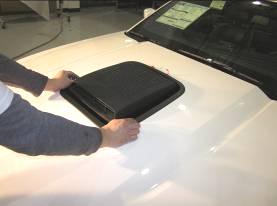
3. Peel 3”-4” of the red backing from the 3M Tape on the Upper Trim Ring (part # 115051) and place in hood opening. Make sure the Trim Ring is facing the correct direction.
4. Line up trim ring with the Shaker Scoop giving even spacing around scoop. When proper placement is achieved, finish peeling the red backing from acrylic bonding tape and press on Trim Ring to set tape to hood.
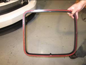
5. Install the Lower Trim Ring onto the Upper Trim Ring’s flange, squeeze until Trim Rings snap together. The Lower Trim Ring will hold the hood blanket in place around the opening.
Note: Squirter Hose will be supported and concealed by the Lower Trim Ring.
6. There are two 3/32” holes that are predrilled in the front and rear of the Upper and Lower Trim Rings (4 total). Use #183011 rivets to secure the Upper and Lower Trim Rings together.
If you have any questions, please contact [email protected] or give us a call @ 866-624-7997
