FREE 1 to 3-Day Delivery on Orders $149+ Details
How to Install Auto Meter Sport Comp II Boost/Vac Gauge w/ Warning Light - Electric (79-17 All) on your Ford Mustang

Shop Parts in this Guide
Installation
1. Check that you have all parts required for installation, and the engine is cool.
2. Disconnect the negative (-) battery cable.
3. Gauge mounts in a 21⁄16” hole. Use supplied brackets and nuts to secure gauge to dash.
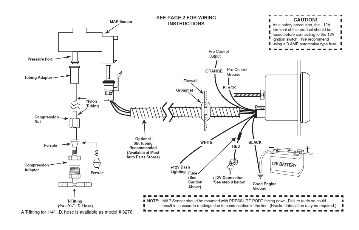
4. Drill 1” diameter hole where wires pass through sheet metal (such as firewall) and install rubber grommet provided. (Grommet will require slit.)
5. Securely mount the MAP sensor to the firewall or inner fender with pressure port facing down. (Bracket fabrication may be required.)
6. Install T-Fitting in a manifold vacuum hose. Attach one end of the nylon tubing to the T-Fitting the compression adapter. Connect the other end of the nylon tubing to the MAP sensor with the tubing adapter. A T-fitting for 1/4” I.D. hose is available as model # 3276.
7. Connect the white wire to dash lighting or switchable 12v light source.
8. Connect the red power wire to a switched 12 volt source that maintains power during engine cranking and black wire to ground. Most vehicles break the electrical connection to accessories while the engine is being started. If the boost gauge is connected to one of these circuits, the auto zero function will not work properly and inaccurate readings will result. To determine whether a switched source maintains power during starting, look for electrical accessories in the vehicle that remain on while the engine is being started. Connect the red power wire to the same circuit that powers one of these accessories. The connection can be tested by turning the key switch from off to on, the pointer will move backward to the stop pin and then move to zero. Once the pointer has reached zero, start the engine. If the pointer reads vacuum without returning to the stop pin, a suitable connection has been found. If the pointer moves to the stop pin and then reads vacuum, another power circuit must be found.
9. Reconnect negative (-) battery cable.
Power-Up
The pointer will move backward to the stop pin and then move to the zero box. This procedure is an auto-calibration function and is performed on every power-up. While this test is being performed, the gauge may make a clicking sound. This is normal.
Electronic Boost/Vac gauges are equipped with an auto zero function used to compensate for operation at varying altitudes. This function takes a pressure reading during the time that the key switch “flies through” from the ON position to the START position. The reading represents 0 pressure and is used to set the zero point on the gauge each time the engine is started.
Warning Indicator
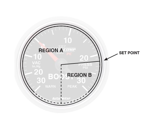
To adjust the warning set point, momentarily press and release the WARN button. The warning light will begin to flash and the pointer will move to the previous set point signifying that warning set mode has been selected. Once in set mode, press the WARN button to move the pointer down, or press the PEAK button to move the pointer up. Warning set points can only be set in the pressure range. Three seconds after the last button press, the warning light will stop blinking and the pointer will return to the current pressure reading. The warning set point is retained when power is removed from the gauge. The warning set point is also the Pro Control set point.
Warning Indicator
To adjust the warning set point, momentarily press and release the WARN button. The warning light will begin to flash and the pointer will move to the previous set point signifying that warning set mode has been selected. Once in set mode, press the WARN button to move the pointer down, or press the PEAK button to move the pointer up. Warning set points can only be set in the pressure range. Three seconds after the last button press, the warning light will stop blinking and the pointer will return to the current pressure reading. The warning set point is retained when power is removed from the gauge. The warning set point is also the Pro Control set point.
Peak Recall
Press and hold the PEAK button to recall the highest pressure reading since the memory was last cleared. To clear the memory, press and hold the PEAK button, and while still holding the PEAK button, press the WARN button. The pointer will move to the stop pin to indicate that the memory has been cleared. Release the PEAK and WARN buttons to resume normal operation. The peak recall point is retained when power is removed from the gauge.
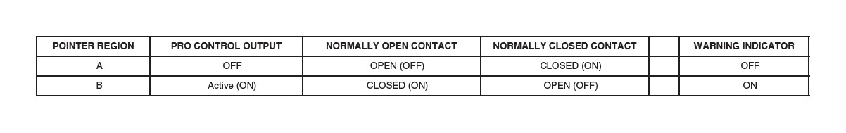
Pro Control
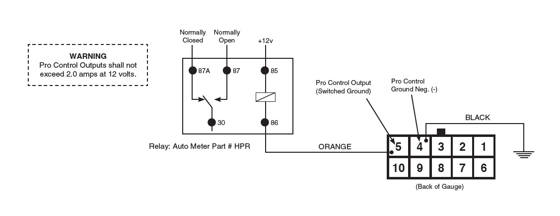
The Pro Control feature activates a switched ground output at a user defined set point.
Pro Control can be used to switch on a relay to activate ignition kill, cooling fans, lamps, alarms, etc.
The Pro Control set point is the same as the Warning Indicator set point. Follow the directions above for Warning Indicator to change the set point.
The set point defines two regions on the gauge dial, the region below the set point and the region above the set point. Like the Warning Indicator on the gauge, the Pro Control
output is active in the region above the set point (high pressure).
PRO CONTROL RELAY DIAGRAM
SERVICE
For service send your product to Auto Meter in a well packed shipping carton. If you are sending product back for Warranty adjustment, you must include a copy (or original) of your sales receipt from the place of purchase.