 FREE 1 to 3-Day Delivery on Orders $149+ Details
How to Install an Edelbrock E-Force Stage 1 Street Supercharger Kit on a 2011 - 2013 GT Mustang
Installation Time
1 days
Tools Required
- Jack and Jack Stands OR Service Lift
- Panel Puller
- Ratchet and Socket Set including 7mm, 8mm (deep), 10mm (deep), 12mm, 13mm, 15mm
- 5mm & 6mm Allen Sockets
- 19mm Wrench
- 3/8” Breaker Bar
- Screwdrivers
- Pliers OR Hose Clamp Pliers
- Impact Wrench
- Blue Loctite
- O-ring Lube
- Masking Tape
- 90° Drill
- 1” Stepped Drill Bit
- Torque Wrench

Shop Parts in this Guide
INTRODUCTION
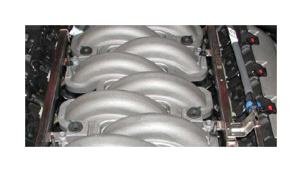
Thank you for purchasing the Edelbrock 5.0L Ford Supercharger System for the Mustang GT. The Edelbrock E-Force Supercharger System for the 2011 5.0L 3V Mustang utilizes Eaton’s new Gen VI TVS Supercharger rotors, featuring a four lobe design with a full 160° of twist for maximum flow, minimum temperature rise, quiet operation, and the reliability for which Eaton is known. These rotors however, are merely the foundation of the system. The Edelbrock Supercharger is a complete system that maximizes efficiency and performance by minimizing air restriction into, and out of, the supercharger. This results in maximum airflow, with minimum temperature rise and minimum power consumption. In addition, Edelbrock inverted the supercharger and packaged it down low in the valley, allowing for an incredible, industry leading, 15 inches of runner length, maximizing low end torque. The supercharger housing itself is integrated into the intake manifold for a seamless design with minimal components, eliminating the possibility of vacuum leaks between gasket surfaces. The system also utilizes a front drive, front inlet configuration giving it the shortest, least restrictive inlet path on the market. Sitting right above the supercharger and below the enormous runners is the largest air to water intercooler available, measuring an astonishing 110 square inches. Last but not least, the E-Force supercharger is without a doubt the best looking engine compartment upgrade imaginable. It features a uniquely styled plenum, and includes matching side covers. In summation, the Edelbrock supercharger will provide you with the most power at the lowest amount of boost resulting in neck snapping performance that is safe to operate on a completely stock engine. It is also pending 50 state emissions legality, and can be had with an optional 5 yr 60,000 mile warranty so that there are no worries when installing it on your brand new car.
IMPORTANT WARNINGS
Before beginning installation, use the enclosed checklist to verify that all components are present in the box then inspect each component for damage that may have occured in transit. If any parts are missing or damaged, contact Edelbrock Technical Support, not your parts distributor.
Proper installation is the responsibility of the installer. Improper installation will void warranty and may result in poor performance and engine or vehicle damage.
Due to the complexity of the Edelbrock E-Force Supercharging system, it is recommend that this system only be installed by a qualified professional with access to a service lift, pneumatic tools, and a strong familiarity with automotive service procedures. To qualify for the optional 3-year, 36,000 mile warranty, it is necessary to have this system installed by a certified ASE technician, Ford dealership, or Edelbrock approved installer. Failure to have this system installed by a properly certified service center may result in voiding of both the optional warranty offered with this sytem, as well as the standard Edelbrock parts warranty. Please contact the Edelbrock Technical Support department if you have any questions regarding how this sytem and/or your installer of choice will affect any warranty coverage for which your vehicle may qualify.
Any previously installed aftermarket tuning equipment must be removed and the vehicle returned to an as stock condition before installing the supercharger.
Any equipment that directly modifies the fuel mixture or ignition timing of the engine can cause severe engine damage if used in conjunction with the Edelbrock E-Force Supercharger System. This includes, but is not limited to: ignition boxes, air/fuel controllers, OBDII programmers, and any other device that modifies signals to and/or from the ECU. Aftermarket bolt-on equipment such as underdrive pulleys or air intake kits will also conflict with the operation of the supercharger and must be removed prior to installation. Use of any of these products with the E-Force Supercharger could result in severe engine damage.
The supercharger manifold includes a 1/8 NPT port to accommodate the installation of a boost gauge or pressure transducer. Remove the plug and replace it with a fitting to attach your gauge or sensor.
The supercharger has been pre-drilled and tapped for a 1/8” NPT fitting at the rear of the passenger side intake runner flange. There is currently a plug sealing the hole, which can be removed, and replaced with a fitting to adapt to your sensor. CAUTION: Never cut into the vacuum lines leading to the bypass actuator, on the driver’s side of the manifold, for the purpose of tapping in a boost gauge, as this will result in boost pressure readings that are higher than what is actually present in the intake plenum.
91 octane or higher gasoline is required at all times. If your vehicle has been filled with anything less, it must be run until dry and refilled with 91 or higher octane gasoline twice prior to installation.
Do not use a wibeband oxygen sensor in place of the rear O2 sensor when dyno testing this supercharger system. The voltage signal will cause the fuel system to run lean and possible engine damage.
Edelbrock periodically releases improved versions of the calibration file found on the supplied handheld programmer. Check the website to ensure you have the latest version, as described in step #209.
1. Remove any front strut tower brace, if equipped, and the plastic engine cover.
2. Use an 8mm socket to remove the negative battery terminal clamp. Tuck it to the side to prevent any accidental contact with the negative battery terminal.
3. Use an 8mm socket to loosen and remove the positive battery terminal clamp, then tuck it over to the side.
4. Use a flat blade screwdriver to pry up the head of the eight push-pins that retain the radiator shroud, then use a panel puller to fully remove the push-pins. Lift the shroud off the car and set it and the push-pins aside.
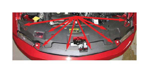
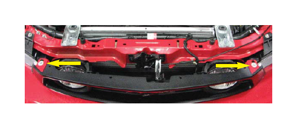
5. Use an 8mm socket to remove the two upper fascia bolts located between the grille and headlights.
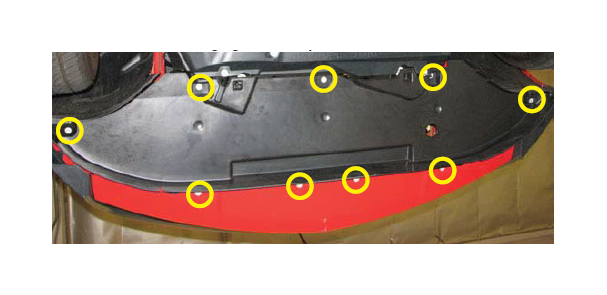
6. Raise the front of the vehicle using a jack and jack stands or a service lift. Remove the nine 7mm bolts retaining the lower splash shield. Pull down slightly on the shield to disengage the clips and remove it.
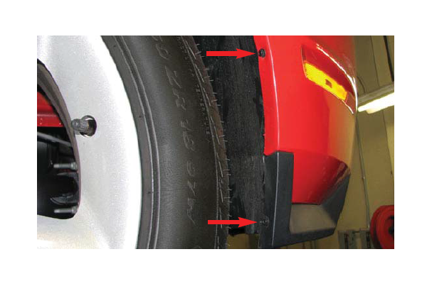
7. Use a 7mm socket to remove the two bolts from the bottom, leading edge of each front wheel well.
8. Remove the five push pins retaining the front half of both front wheel well liners. Note that the two top pins pass through both the front and rear liners. Remove the front half of the liner on both sides of the car.
9. Reach behind the fascia to disconnect the indicator connectors on each side of the vehicle.
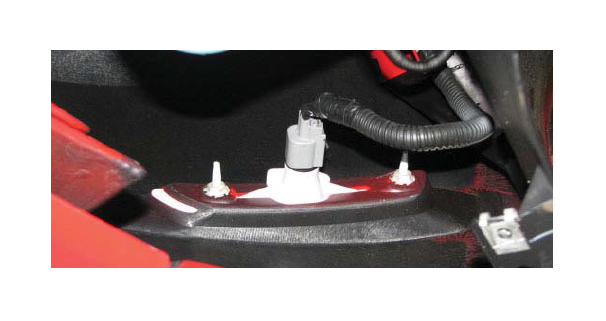
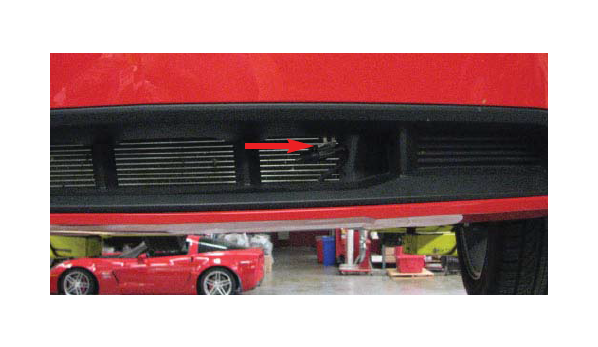
10. Detach the ambient air temperature sensor from its bracket at the front of the car then lower the car.
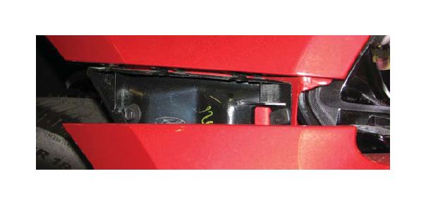
11. Pull the top, rear corners of the fascia away from the fender until the two clips on each side disengage. Lift the two top fascia tabs over the lock clips near the headlights then pull the fascia forward slightly to access the driving light connectors. Once the driving light connectors are detached, the fascia can be removed and set aside.
12. Detach the driver side PCV hose from the air inlet tube and the valve cover and set it aside for reuse later.
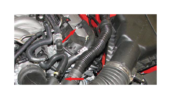
13. Use a 10mm socket to remove the bolt retaining the induction roar resonator diaphragm and lift it up to pull the induction roar resonator tube out of the firewall. Insert the grommet supplied in Bag #1 in the hole left in the firewall. Pull the tube bracket off of the strut tower and the air box.
14. Loosen the throttle body and air box cover worm clamps then remove and discard the inlet tube assembly. Vehicles equipped with an automatic transmission will also need to detach the brake booster hose from the tube.
15. Disconnect and discard passenger side PCV tube.
16. Disconnect the EVAP solenoid connector at the top of the throttle body flange on the manifold.
17. Use an 8mm socket to remove the two bolts retaining the EVAP solenoid then squeeze the tabs to disconnect the EVAP tube. Set the solenoid aside for reuse later.

18. Remove the EVAP tube by detaching it from its retaining clips and hard line then set it aside for reuse.
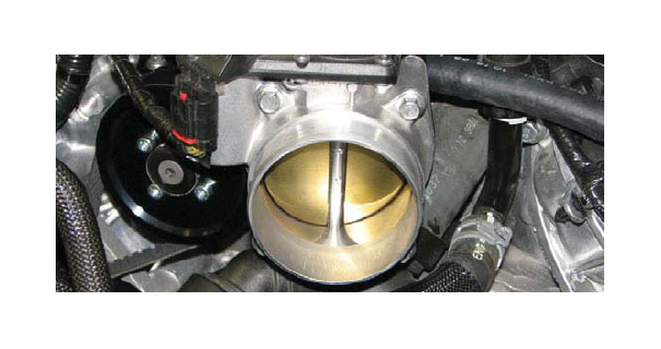
19. Use a 10mm socket to remove the four throttle body bolts then disconnect the throttle body electrical connector. Set the throttle body aside for reuse later.

20. Use a 10mm socket to remove the four nuts at the top of the manifold.
21. Disconnect the brake booster hose from the booster and the manifold and set it aside for reuse later.
22. To avoid injury be sure the engine has fully cooled before draining the cooling system. Release any excess pressure in the system by using a cloth to rotate the radiator cap counterclockwise. Step away from the vehicle if any hot vapor is vented, then remove the cap.
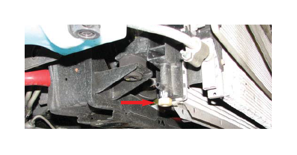
23. Place a drain pan below the passenger side radiator petcock then use a 19mm wrench to loosen the petcock and drain the engine coolant. The system only needs to be drained until the water level is below the intake flange.
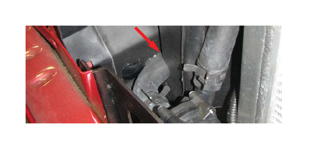
24. Detach the two heater hoses and the coolant overflow hose from the front of the engine.
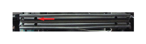
25. Remove the two foam fuel rail bumpers from the top of the manifold and discard them.

26. Detach the fuel injector electrical connectors.
27. Place a shop rag around the fuel line fitting to absorb excess gas then depress the blue lock tab and pull the fuel line off the rail. Use caution when removing this hose as the fuel is still pressurized and will spray a bit.
28. Use a 10mm socket to remove the four fuel rail bolts, then lift the injectors out of their provisions. The rails and injectors can be removed together and discarded.
29. Use an 8mm socket to remove the ten manifold bolts.
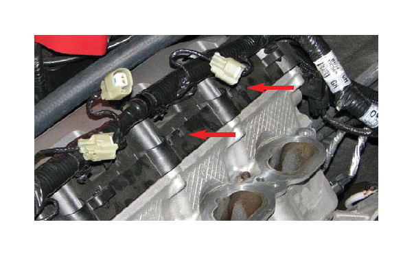
30. Pull the manifold forward slightly to remove the four main engine wiring harness pins. Once the pins have been detached, remove the manifold.
31. Carefully remove the eight o-ring seals from the manifold flanges and set them aside for reuse later.
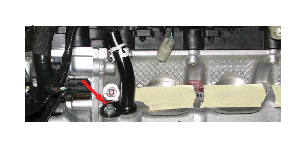
34. Use an 8mm socket to remove the bolt retaining the passenger side coolant nipple. Pull the nipple out of the cylinder head and set it aside for reuse later.
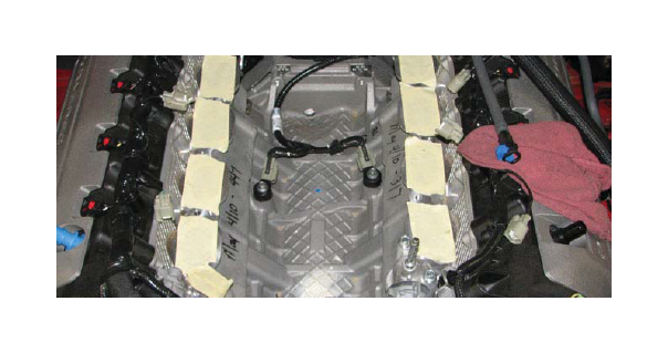
35. Use a soft cloth to remove any contaminants on the sealing surfaces of the cylinder heads. Use masking tape to prevent any debris from entering the exposed ports.
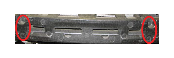
36. Use a panel puller to remove the four pins retaining the foam bumper, then set them and the bumper aside.
37. Remove the plastic shrouds located on either side of the radiator by removing the plastic clips that hold them in with a panel puller. Removing the airbox, while not necessary, will make removing the driver side shroud much easier.
38. Use a 13mm socket to remove the passenger side, upper inside bumper bolt then replace it with the M8 x 30mm long hex flange bolt and M8 washer included in hardware bag #5.
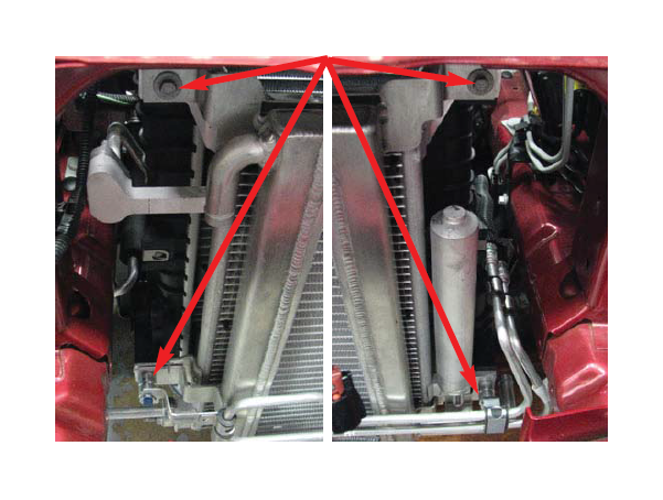
39. Remove the two bolts and two nuts that hold the AC condenser in place. Be careful as you remove the fourth screw as the condenser will be loose and only held in place by the AC hoses and surrounding components.
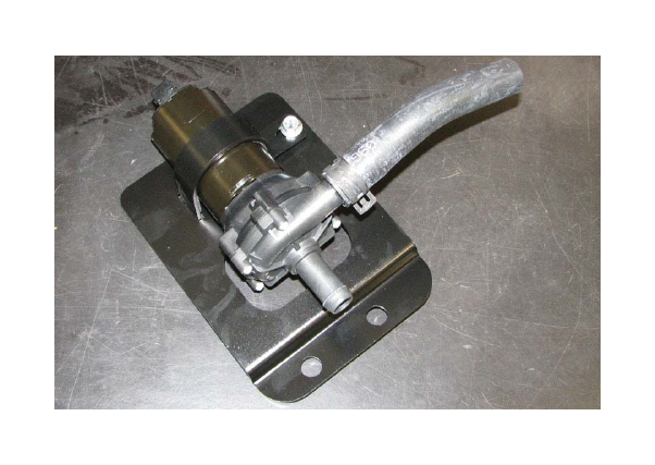
40. Install the heat exchanger in front of the condenser so that the downward bent tube is on the passenger side, then raise the heat exchanger and condenser together and secure them using the stock fasteners. 41. Mount the water pump onto the water pump bracket by sliding the bent edge of the strap into the notch on the bracket and using a 12mm socket to tighten the supplied bolt on the other end of the strap. Orient the pump so that the outlet will point up and back towards the intercooler inlet, while the water pump intake will point towards the passenger side fender.
42. Fit the short molded hose onto the outlet of the water pump and secure it with a hose clamp.
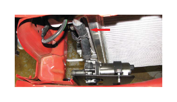
43. Slide an extra clamp onto the outlet hose, then install the water pump and bracket by sliding it over the two inside bumper bolts on the passenger side. Slide the outlet hose onto the inlet tube of the heat exchanger then secure it by sliding the hose clamp up and into place.
44. Route the long molded hose under the fuse box to the intake of the water pump. Hold the passenger side shroud in place to visualize where the hose will pass through it, then use a stepped drill bit to cut a 1” diameter hole in the shroud.
45. Reinstall the passenger side shroud, then feed the inlet hose through the hole and clamp it to the water pump intake. Secure the pump bracket by installing the supplied M8 flange nuts with a 13mm deep socket.
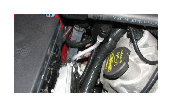
46. Install the long 3/4” hose onto the driver side barb of the heat exchanger and secure it with a clamp. Route the rest of the hose around the A/C hard line, avoiding close proximity to the exhaust manifold and power steering pump, and up between the engine and driver side fender.
47. Reinstall the driver side radiator shroud along with the airbox, if it was previously removed.
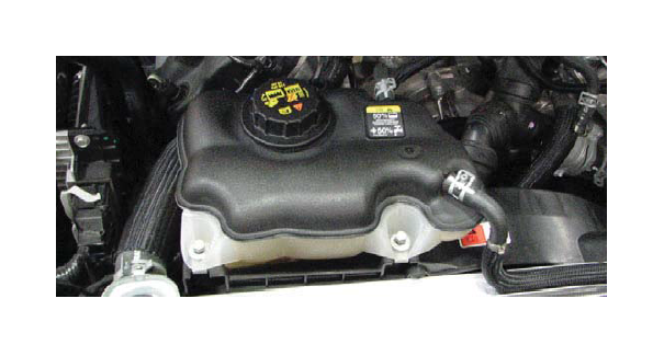
48. Use a 10mm socket to loosen and remove the two bolts supporting the coolant reservoir. It is not necessary to fully remove it, just loosened so that it can be shifted.
49. Use a 15mm socket to loosen the tensioner and remove the stock belt. Use a 13mm socket to remove the stock tensioner from the front engine cover.
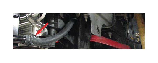
50. Disconnect the upper radiator hose from the radiator.
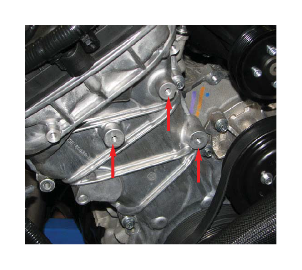
51. Use a 90° drill and the supplied drill bit to drill out the three holes on the passenger side of the front engine cover. The upper and outboard holes should be drilled .72” deep while the inboard hole should be drilled 1.01”. Tap the holes to M8 x 1.25 with the supplied tap.
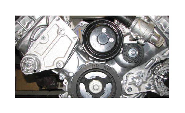
52. Secure the new tensioner bracket to the bosses that were just drilled and tapped with bolts supplied in Bag #3. Use the 40mm bolt in the top hole, the 20mm bolt in the inboard hole, the 25mm countersunk bolt in the middle hole and the 90mm bolt behind the tensioner provision.
53. Secure the idler bracket by installing the 110mm bolt through the ear of the alternator, the 90mm bolt into the top, front cover hole and the 45mm bolt through the lower hole that was used to secure the stock tensioner.
54. Install the tensioner with a 65mm bolt and the three idler pulleys with M8 x 20mm bolts and washers, all supplied in Bag #3. The smaller 65mm pulley should be installed on the uppermost boss on the tensioner bracket.
55. Remove the bolt that secures the air conditioning hard line bracket (if present, not all vehicles so equipped) and gently bend the AC line until it can be attached using the bracket and M6 x 16mm bolt supplied in Bag #3.
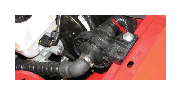
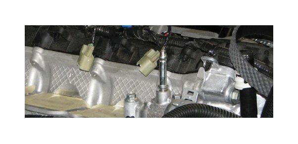
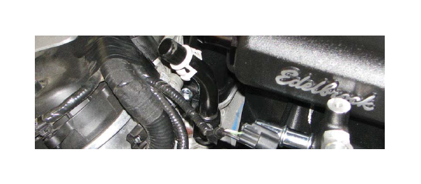
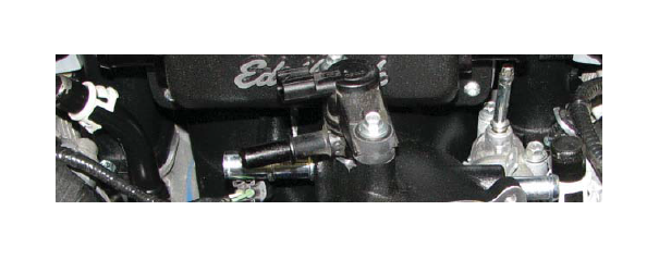
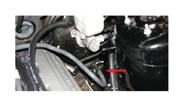
56. Locate the small fitting extending vertically from the thermostat housing. Use an 10mm socket to gently bend this fitting roughly 5° outboard so that it will clear the supercharger manifold.
57. Remove the coil covers from the cylinder heads, then remove the ignition coils to access the spark plugs. Remove the plugs with a 5/8” spark plug socket and gap them to .034”. Reinstall the plugs and torque them to 9 ft-lbs., then reinstall the coils and coil covers. Be sure to install the plugs and coils in the same spot they came off.
58. Install the stock o-ring seals into the grooves on the intake flanges of the supercharger. Be sure to line up the tab on the o-rings with the notches provided.
59. Be sure that the engine bay and environs are clean and free of debris, then remove the masking tape used to protect the intake ports from contamination.
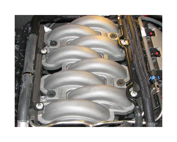
60. With the help of an assistant or a cherry picker, carefully lower the supercharger assembly onto the cylinder heads. Be especially careful not to pinch any wires between the supercharger and the cylinder heads.
61. Ensure correct alignment of the supercharger by sighting through the fuel injector bores and adjusting the manifold until it is centered left to right as well as front to back on the engine block.
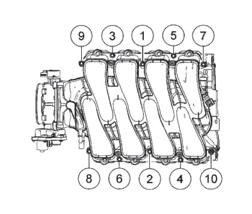
62. Use a 10mm socket to install the intake bolts supplied in hardware bag #1 then torque them to 8 ft-lbs in the sequence shown below.
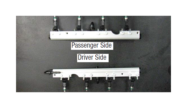
63. Install the black anodized plugs supplied with the fuel rails on both ends of the passenger side rail and in the rear provision of the driver side rail.
64. Install the supplied black anodized 180° fittings into the front provision of the driver side rail and in the bottom, center provision of both rails so that they extend inward toward the supercharger.
65. Clip the supplied fuel crossover hose onto the 180° shaped fittings installed in the center of each rail. 66. Install the injector alignment brackets onto the fuel rails using the bolts supplied in Bag #1.
67. Apply o-ring lube to both ends of the supplied fuel injectors, then install them into the supplied fuel rails, oriented so that the electrical connectors will face away from the supercharger.
68. Trim the back two valve cover tabs on the passenger side and the front two on the driver side.

69. Mark the actuator rod where it goes into the actuator body so that it can be reinstalled in the same position, then unbolt the actuator from the manifold.
70. Lower the fuel rail assembly onto the supercharger and line up the fuel injectors with their provisions on the manifold. Push down on the rails gently until the fuel injectors are fully seated then install the four M6 x 30mm bolts supplied in Bag #1 to secure the rails.
71. Line the actuator rod up with the mark previously made, then reinstall the actuator bolts.
72. Connect each of the fuel injectors to the appropriate terminal on the main engine wiring harness.
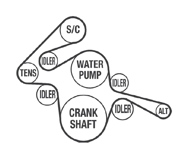
73. Install the supplied belt according to the routing diagram shown, then use a 3/8” drive breaker bar to rotate the tensioner enough to fully install the belt.
74. Clip the stock fuel inlet line into the 180° fitting on the front end of the driver side fuel rail.
75. NOTE: The following two steps apply to vehicles equipped with a manual transmission only. Remove the hose clamp that secures the bulk of the brake booster hose assembly to the 90° plastic fitting then pull the hose off the fitting.
76. Attach the supplied brake booster hose to the 90° plastic fitting previously attached to the stock brake booster line, then attach the short length of 1/2” hose on the other end of the fitting to the nipple on the driver side of the air inlet and secure it with the stock clamp.
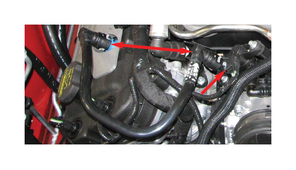
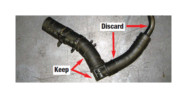
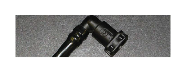
77. NOTE: The following step applies to vehicles equipped with an automatic transmission only. Remove the brake aspirator and molded hose from the stock brake hose assembly. Trim stock 1/2” and 3/8” molded hoses and assemble the components as shown in the picture below. Insert the supplied 90° fitting into the molded hose, attach the 1/2” hose to the manifold fitting, then attach the supplied 3/8” hose to the aspirator.
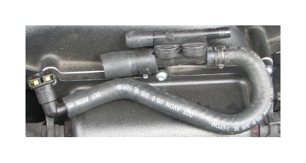
78. Route the rest of the supplied 3/8” brake hose along the driver side cylinder head and attach it to the fitting on the brake booster and secure it with a clamp.
79. Reinstall the passenger side coolant nipple and attach the stock heater hoses to the fittings on the heads.
80. Install the stock EVAP solenoid on the provision at the top of the nose inlet using the stock bolts and o-ring.
81. Install the stock throttle body on the nose inlet using the stock o-ring seal and bolts.
82. Use a razor blade or Exacto knife to carefully cut the end of the stock EVAP hose that attaches to the solenoid and remove the fitting. Use caution not to damage the fitting in the process. Install this fitting into the supplied EVAP solenoid hose.
83. Install the supplied EVAP hose on the EVAP solenoid and route it back along the passenger side fuel rail, around the back of the engine and down to attach it to the EVAP hard line located below the brake booster.
84. Install the stock driver side PCV hose onto the passenger side PCV fitting and attach it to the passenger side of the supercharger manifold.
85. Mount the supplied water pump wiring harness relay on the front of the fuse box housing next to the ECU.
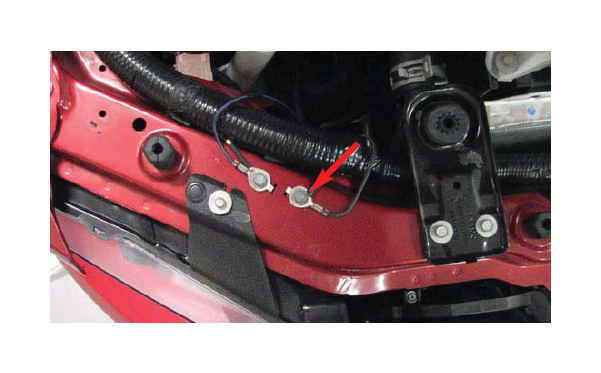
86. Route the ground wire to the inboard grounding bolt.
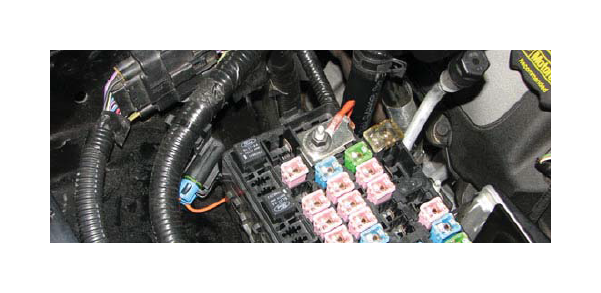
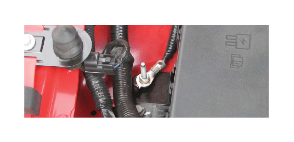
87. Route the longer wire harness segment under the fuse box and attach the fuse holder to the passenger side strut tower with a 10mm socket and the M6 bolt supplied in hardware bag #7. The large white electrical connector can be removed by sliding it to the right for easier access to the bolt. Replace the connector once the fuse holder is mounted.
88. Use a 10mm socket to attach the power wire to the power terminal on the fuse box.
89. Route the water pump electrical connector below the fuse box and around the washer fluid reservoir and plug it into the intercooler water pump.
90. Attach the stock EVAP solenoid connector on the main engine wiring harness to the matching connector on the water pump harness then attach the water pump harness connector to the EVAP solenoid.
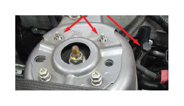
91. Remove the two inboard strut tower nuts from the passenger side strut tower.
92. Remove the 10mm ground strap from the passenger side strut tower bracket and pull out the harness body pin. Route the strap to the ground stud on the outboard side of the fuse box and secure it with the nut supplied in Bag #7.
93. Attach the long molded hose to the bottom barb of the recovery tank and secure it with a clamp.
94. Hang the recovery tank bracket from the exposed strut tower studs. Bend the A/C service port slightly so that it is positioned between the recovery tank and the passenger side fender.
95. Install the short straight hose from the recovery tank to the passenger side intercooler fitting and secure both ends with the supplied hose clamps.
96. Install and torque the strut tower nuts to 26 ft/lbs.
97. Install the throttle body elbow onto the throttle body and secure it with the provided hose clamps. The flexible elbow should be oriented so that it can be easily mated to the air cleaner cover outlet tube.
98. Owners of an automatic transmission vehicle will need to remove the cap from the fitting at the bottom of the throttle body elbow and attach the molded hose connected to the brake aspirator. Owners of a manual transmission vehicle must leave the cap in place.
99. Install the supplied driver side PCV hose.
100. Plug the MAF/Temp wiring harness into the Temp sensor then route the rest of the harness along the inside of the driver side fender to the front of the air box.
101. Seperate the MAF harness connector from the MAF sensor located at the outlet of the airbox. Connect the engine harness to the connector on the MAF/Temp harness then attach the MAF/Temp harness to the MAF Sensor. Reattach the harness to the tab on the airbox.
102. Connect the heat exchanger to intercooler hose to the fitting on the driver side of the manifold and secure it with a clamp.
103. Reinstall the foam bumper insulator and secure it in place with the stock body pins.
104. Reconnect the fog lights and indicators, then replace the fascia onto the front of the car.
105. Reinstall the screws and push in rivets that secure the inner fender wells, then reinstall the top front fascia bolts.
106. Replace the lower splash shield and secure it with the stock fasteners. The vehicle can now be lowered.
107. Verify that the coolant petcock is closed, then refill the coolant system.
108. Fill the intercooler system with a 50/50 blend of water and coolant poured into the recovery tank. Fill the tank until the water level is roughly 1” from the top of the threaded neck.
109. Turn the ignition key to the ‘ON’ position.
110. Verify that water is flowing briskly through the recovery tank, then install the cap. XV. Flashing the ECU
111. Plug the supplied programming module into the OBD-II port of the car, located below the steering column.
112. Once the main menu has loaded, press the central ‘select’ button on the controller to access the ‘Performance Tune’ option.
113. Read the discalimer carefully, then choose ‘Agree’ and press select.
114. Use the arrow buttons to select your transmission, then press select to confirm your selection.
115. Select ‘Edelbrock E-Force 5psi’ from the menu.
116. Read the description and press select.
117. The programmer will automatically save a copy of your existing engine tune. Press select to continue.
118. Turn the ignition key to the ‘OFF’ position when prompted, but do not remove it.
119. Turn the ignition key to the ‘ON’ position when prompted, but do not attempt to start the car. The programmer will automatically start saving the stock calibration.
120. Once complete, follow the on-screen prompts regarding key position until you are given the option to ‘Install Tune’ or ‘Modify Tune’. Choose ‘Modify Tune’ and press select.
121. Read the disclaimer and press select.
122. Select ‘Modify Parameters’ and press select.
123. Press select to choose ‘Axle Ratio’.
124. Press select to choose ‘Axle Ratio’, again.
125. Use the directional buttons to choose the number closest to your axle ratio (printed on the differential cover) and press select.
126. Press select to confirm your choice.
127. An asterisk will appear next to the ‘Axle Ratio’ option to signify that your changes have been saved. If your Mustang is equipped with non-stock tires, choose the ‘Tire Revs per Mile’ option and press select; otherwise, proceed to step 196.
128. You will need to check your tire manufacturer’s website to determine the tire revolutions per mile for your tires. The stock tires get 771 revs per mile.
129. Use the directional buttons to select the number closest to the tire revs per mile figure provided by your tire manufacturer. Press select again to confirm your selection.
130. Press escape twice to return to the Performance Tune menu. Choose ‘Install Tune’ and press select.
131. Confirm your choice by pressing select.
132. Follow the on-screen prompts regarding key position until you recieve notification that the tune installation is complete.
133. When the download is complete you will be prompted to disconnect the DiabloSport Performance Tuner from the OBD-II port of your vehicle.
134. If you have access to a diagnostic scan tool, run a ‘Key On, Engine Off’ test to verify that all connectors are properly installed, otherwise move on to the next step.
135. Start the car and verify a smooth idle. If you are using a diagnostic scan tool, run a ‘Key On, Engine Run’ test.

