 FREE 1 to 3-Day Delivery on Orders $149+ Details
How to Install Exedy Mach 350 Stage 1 Clutch on your Mustang
Installation Time
4 hours
Tools Required
- Floor jack, jack stands, and car ramps
- 3/8” drive ratchet, with long and medium extensions
- 3/8” drive swivel
- 3/8” breaker bar / cheater bar
- 7/8” combo wrench
- 8mm, 10mm, 13mm, 15mm, 17mm sockets (short or deep)
- 12mm 12-point socket
- Pilot bearing puller attachment, with slide hammer (Rent-a-tool program at your favorite auto store)
- Small flathead screwdriver (optional)
- Needle nose pliers
- Rubber mallet
- Liquid Wrench, PB Blaster, or similar penetrating oil (optional, but likely)
- Brake cleaner
- Super Clean, or similar degreaser/cleaner
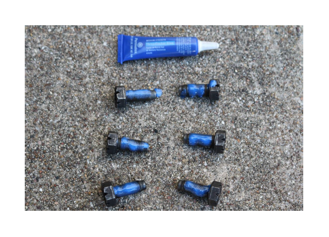
- Blue thread locker
- Permatex black RTV
- Mechanics gloves
- Oil/fluid catch can
- Shop towels
- 3.2 quarts Pennzoil Synchromesh transmission fluid (optional, but recommended)
- Giant piece of cardboard underneath the car while you work
Shop Parts in this Guide
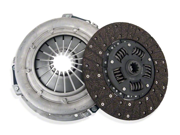
In this write-up, we will be replacing the OEM clutch assembly with an Exedy Mach 350 Stage 1 clutch kit. In addition, a new clutch fork and pivot stud are also on the menu. For my specific application, I was initially looking at replacing just the faulty throwout bearing. However, since we’ll already have the transmission out, we may as well replace everything else to avoid having to go back in there in a week/month.
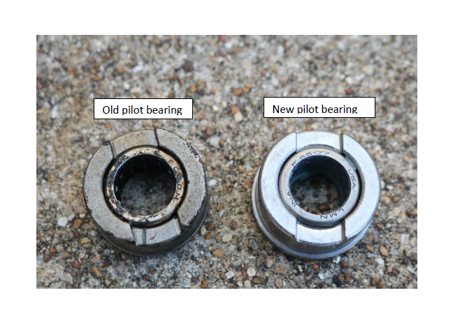
The Exedy Mach 350 Stage 1 Clutch Kit comes with both roller pilot and throwout (release) bearings, the pressure plate, and the friction disc. While we have the transmission removed, as mentioned above it is cheap insurance to also replace the clutch fork and pivot stud.
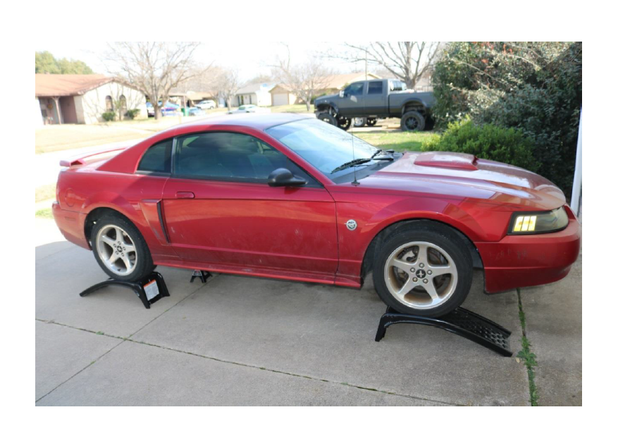
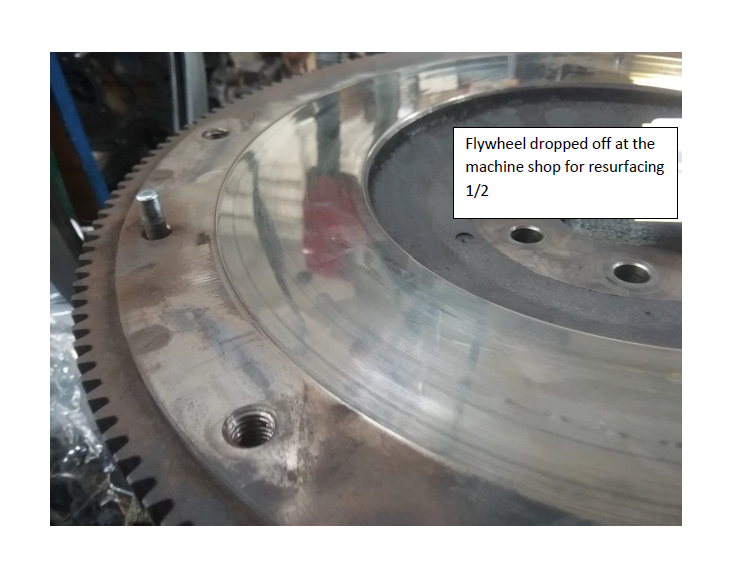
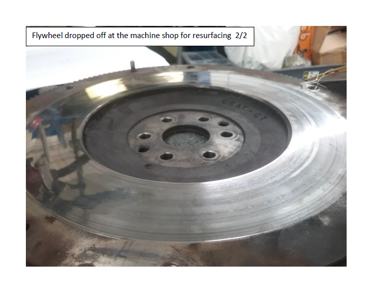
Finally, when replacing any clutch it is recommended to either replace or resurface the flywheel in order to ensure a proper mating surface. As of this write-up, my ’04 GT has just shy of 122,000 miles, and as evidenced by some of the pictures, it appears to have never been serviced.
Please note, I have made every effort to properly identify lesser-known parts, such as the “lower shift boot metal bezel ring” in the shifter assembly, or the “transmission spacer plate”, and also referenced the 2003 Ford Mustang Service Manual for the correct torque specs for reassembly. Some typographical errors may be present, despite best efforts to find and correct them all.
Pictures were taken midway through the process, beginning with the flywheel getting dropped off at the automotive machine shop, and several shots were used multiple times in this write-up.
Because of the age/mileage, I chose to replace the transmission fluid rather than reuse it. As I discovered during this whole process, my transmission fluid looked like used motor oil, leading me to strongly believe this too had never been touched. Tremec’s Service Topic 3-02 on recommended fluids for the TR3650 transmission states to use Dexron III or similar Automatic Transmission Fluid (ATF), referenced here. Ford released TSB 04-15-6 stating to fill the TR3650 transmission with 3.0 Liters (US equivalent of 6.3 pints or 3.17 quarts), referenced here.
As with everything in the DIY realm, safety first!
Thanks for reading! Now, let us begin….
Steps:
1. Elevate your ride. For peace of mind, I put mine up on ramps and turned them in opposite directions for safety.
2. Disconnect the battery! You will be up close and personal with the starter, and metal tools conduct electricity quite well.
3. Remove shifter assembly.
a. Remove shifter knob
b. Remove housing, grasp firmly and pull back and up. There are 4 clips, two on either side
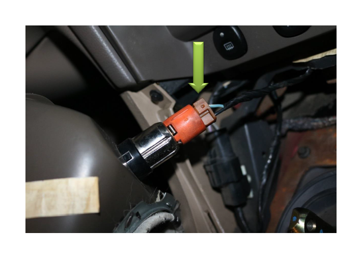
c. Unclip the cigarette lighter connection (flathead screwdriver will help)
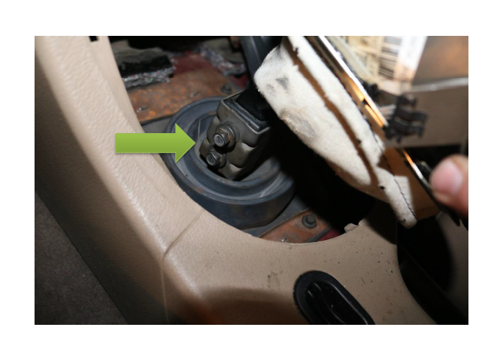
d. Remove shifter handle, 2x 10mm (re-torque to 27 lb-ft)
e. Remove the lower shift boot metal bezel ring, 4x 8mm
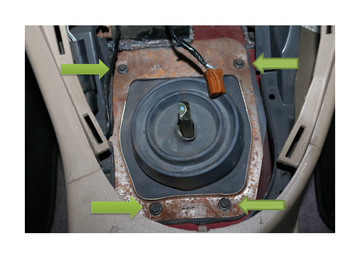
f. Remove the shifter assembly from the transmission, 4x 13mm. For best results, reattach the shifter handle and gently rock it all the way left/right to break the seal. Once loose, pull straight up to remove.
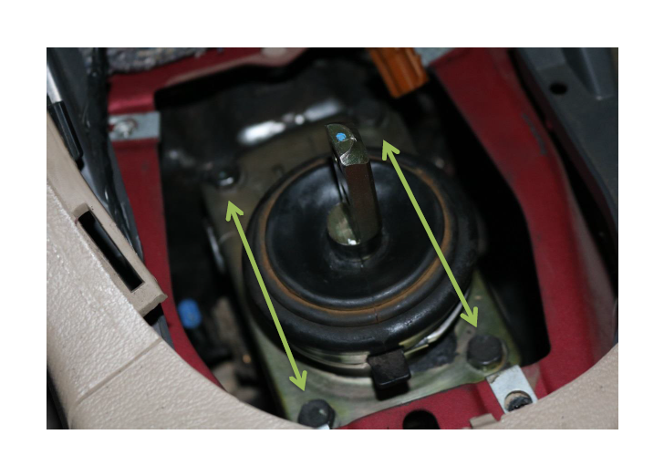
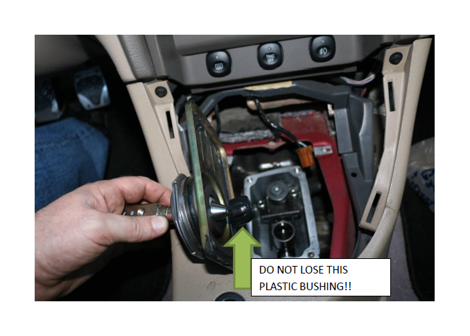
g. There may be some residual transmission fluid on the underside of the shifter assembly. Take care to have a shop towel handy and DO NOT LOSE the plastic shift rod bushing. It will still be attached to the shifter assembly when removed from the transmission. There may also be a permanent gasket in place from previous servicing.
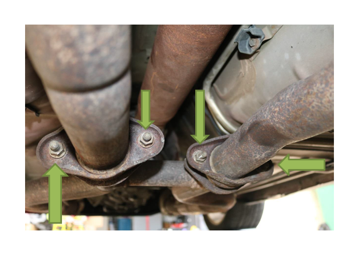
4. Remove the H-pipe. The midpipe contains a total of 8x 15mm bolts, two per side both front and rear. Passenger side bolts at the manifold will require a swivel head attachment to reach.
Note: This is a stock exhaust setup, those configurations with long-tube headers and/or aftermarket exhaust options may alter the removal steps accordingly.
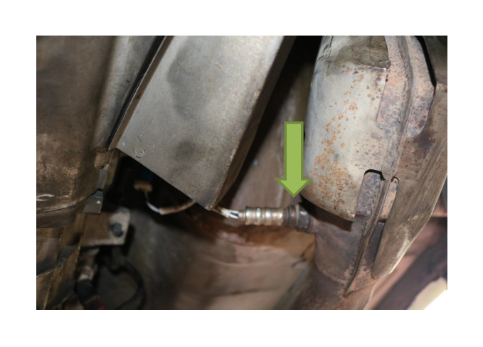
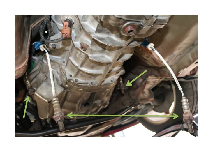
a. Label the O2 sensors (optional) for later reinstallation
b. Remove the O2 sensors, both front and rear, using the 7/8” wrench
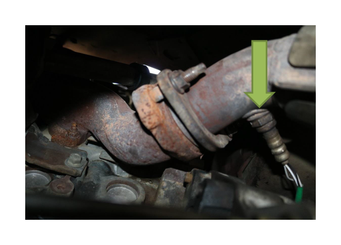
c. 8x 15mm (re-torque the rear 4 bolts to 26 lb-ft and the 4 manifold bolts to 30 lb-ft). Remove the rear four exhaust bolts first, placing a jack stand under the “H” to hold the rear up, then remove the front four bolts at the manifold. The four rear bolts are threaded from the rear.
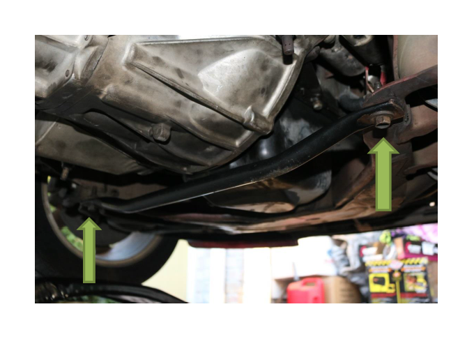
5. Remove the front subframe brace underneath the bell housing. Note: there is a lock-washer on the other end of each bolt.
a. 2x 15mm (re-torque to 30 lb-ft)
6. Remove the starter (ensure you have disconnected the battery!). Note: All 3 starter bolts thread in from the front, and are very difficult to reach from directly underneath it. Use the long extension and swivel to reach them going through the front of the engine bay and over the passenger side A-arm.
a. 3x 13mm (re-torque to 17 lb-ft)
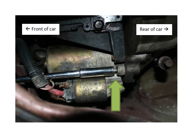
b. Leave the starter connected to the power cabling, and rest on the A-arm secured by a bungee cord or zip ties
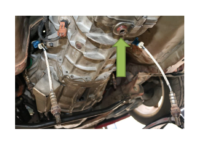
7. Locate the drain plug and drain the transmission fluid into your catch can. a. 3/8” drive ratchet
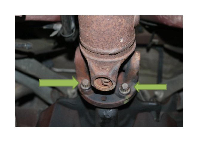
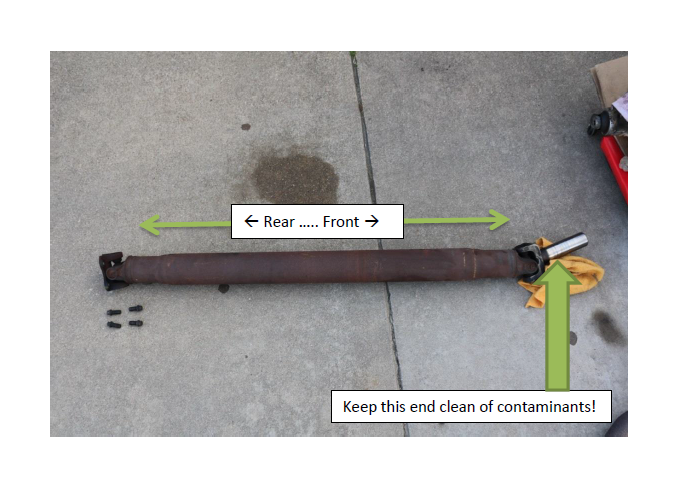
8. Once the transmission has been drained, mark and remove the driveshaft from the differential pinion flange. Note: There may be residual transmission fluid still present. When removing the driveshaft keep the catch can or shop towels handy.
a. 4x 12mm, using the 12-point socket (re-torque to 83 lb-ft). You may need to lift up the rear tires off the ramps and turn the driveshaft to expose the other bolts.
b. Push slightly towards the front to unseat from the lip on the pinion flange
c. Gently slide the driveshaft towards the rear, taking care to catch any residual trans fluid
d. Secure the driveshaft yoke, taking care that no dirt or other contaminants get on or inside
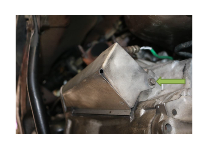
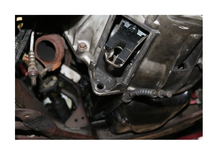
9. Remove the clutch fork dust cover to access and remove the clutch cable.
a. 1x 10mm, the dust cover is located on the driver side of the transmission
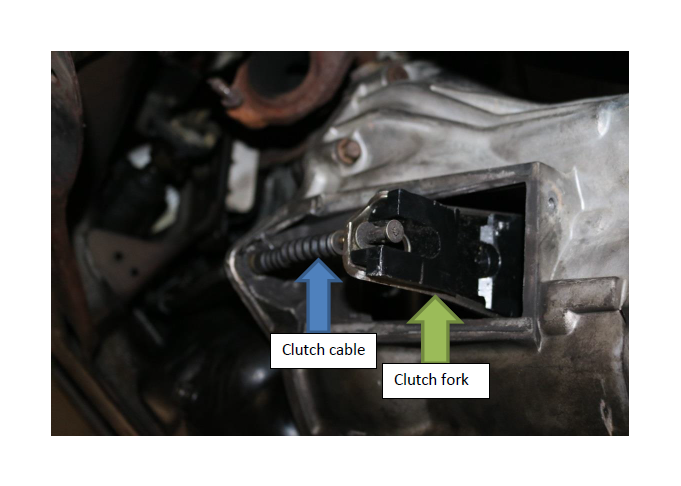
b. Using a pry bar or similar leverage, compress the clutch fork (move it towards the front) enough to relieve and remove the clutch cable. With no tension on the clutch cable, slide it in towards the transmission, then remove through the larger hole.
c. Using needle nose pliers, remove the clutch cable retaining clip
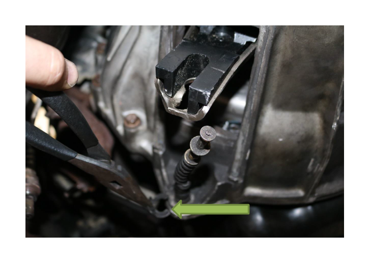
d. Remove the clutch cabling from the transmission and set aside
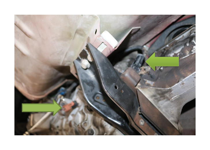
10. Disconnect the reversing lamp switch and the output shaft speed sensor cabling from the transmission.
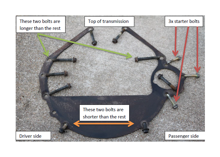
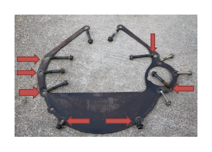
11. Break loose the transmission bolts, but do not remove just yet. Note #1: You will need multiple extensions and the swivel to reach the 2 topmost transmission bolts. To access these two bolts, run the extensions parallel to the length of the transmission. Note #2: There are 12 total bolts of varying sizes, all with a 13mm head. Reference the next picture of the transmission spacer plate for the correct placement and sizing locations. This spacer goes behind the flywheel.
a. 9x 13mm (the 3x starter bolts were removed in Step 6)
b. Support the transmission with a floor jack & transmission adapter attached for maximum stability
c. Remove the top two bolts, break loose the remaining 7 bolts
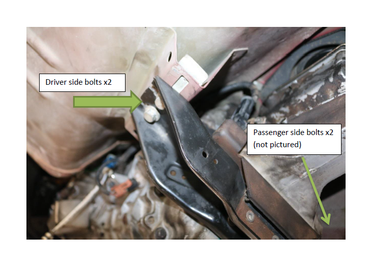
12. Remove the transmission mount/crossmember. Note: Removing the transmission is a 2 or 3-person job because of the weight involved and how cumbersome 120 lbs of metal can be underneath the vehicle.
a. 4x 15mm (re-torque to 40 lb/ft)
13. With the transmission fully supported by the floor jack, remove the remaining bolts at the bell housing. Note: We have already removed 3x for the starter, and 2x at the top, leaving 7 bolts.
a. 7x 13mm (re-torque to 38 lb-ft). Reference the photo in step 11a
b. With a buddy underneath stabilizing the transmission on the floor jack, slowly break the bell housing connection with the rear of the engine block
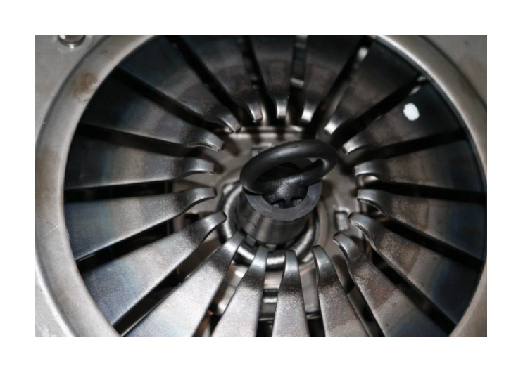
c. Once free and fully supported by the floor jack, slowly take the transmission back to the rear of the vehicle, taking care to not scrape the input shaft against the pressure plate fingers or damage the pilot bearing. Once the input shaft is clear, lower the transmission all the way
d. Slide the transmission out from underneath the vehicle
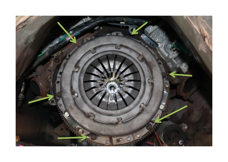
14. Remove the old pressure plate and friction disc. Note: As you remove the outer pressure plate, the inner friction disc (which is not bolted down) will also come free. Take caution as these two parts are deceptively heavy (about 20 lbs).
a. 6x 13mm (re-torque to 24 lb-ft 60 degrees)
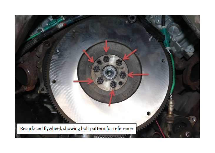
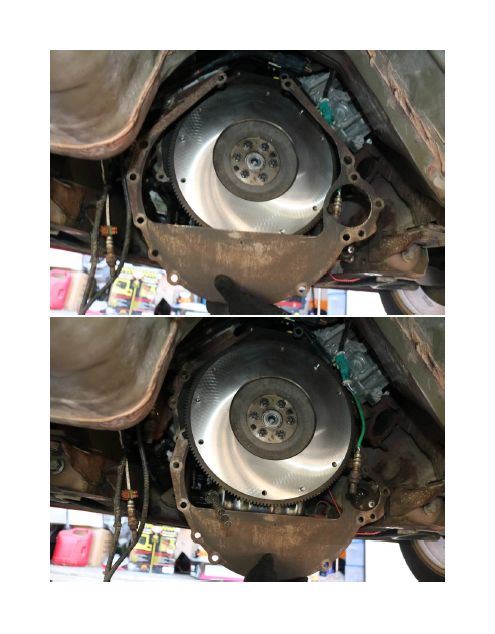
15. Remove the flywheel. Photo was taken after it was resurfaced, before and after pics included for reference. Note: Part weighs about 22 lbs, be careful during removal. Note #2: Removing the flywheel bolts will turn the crankshaft. Have someone hold the crank in position with a 17mm long wrench or similar so it won’t spin. Note #3: The flywheel bolt pattern is very specific. With a sharpie, mark a tooth and a static reference point like the exhaust manifold to greatly assist realignment during reinstallation. PS, sharpie the flywheel tooth, not your own #JustSayin
a. 6x 17mm (re-torque to 59 lb-ft)
16. Remove the pilot bearing.
a. Using the pilot bearing puller attachment, insert into the pilot bearing and open/expand into the grooves. Connect the slide hammer and 2-3 hits should remove the old pilot bearing
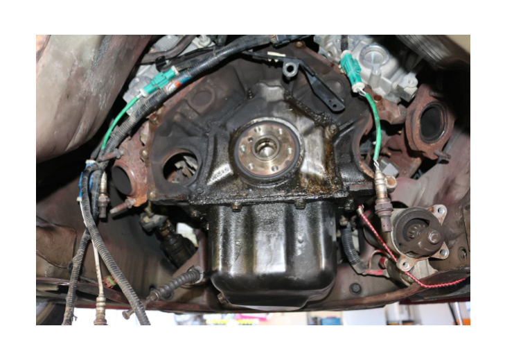
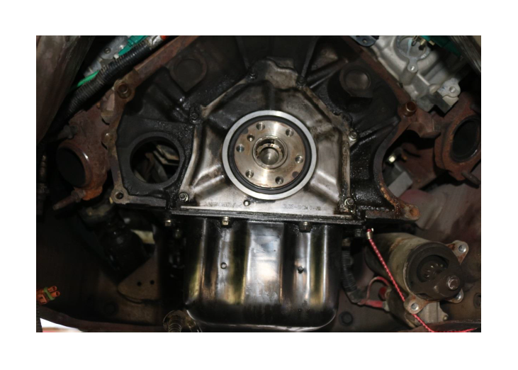
17. Super Clean the rear of the engine block as needed. If the rear seal is bad, now is the time…My mess was due to a leaky oil filter, thankfully.
*****REASSEMBLY *****
18. Replace the pilot bearing.
a. Seat the new bearing evenly into position and gently tap on it with the rubber mallet, taking care to ensure it is reseating evenly. When fully seated, it will be just about flush
19. Install the resurfaced (or new, we don’t judge) flywheel. Take note of any previous alignment markings during disassembly and remount accordingly.
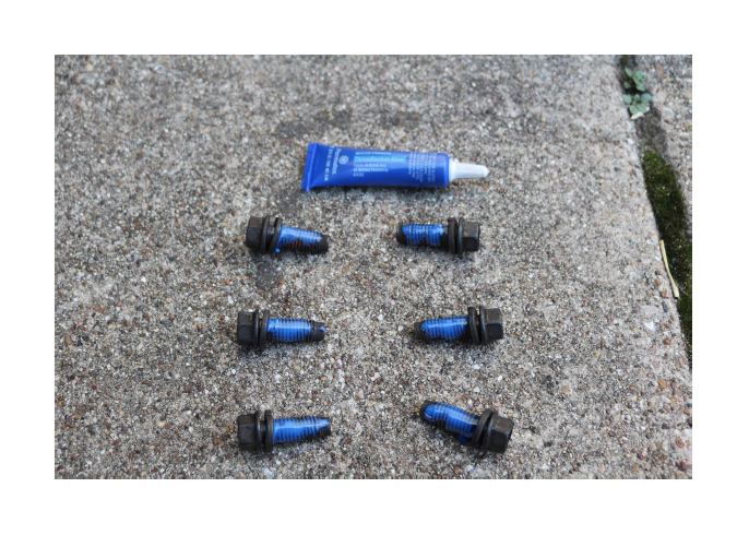
a. Apply thread locker to the 6x 17mm bolts and torque to 59 lb-ft
b. You will need someone to hold the crankshaft in place with 17mm wrench or breaker bar when torqueing down the 6 flywheel bolts
c. Once mounted and secured, clean the surface of the flywheel with brake cleaner to remove residual grease caused by gloved hands or fingers
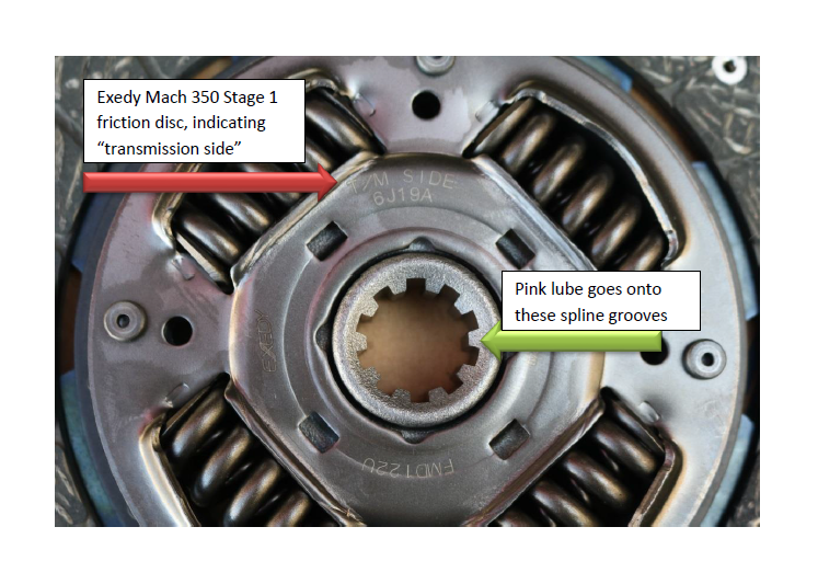
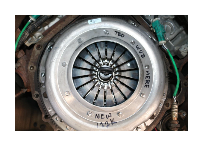
20. Install the Exedy Mach 350 Stage 1 friction disc and pressure plate.
a. Using the provided tube of pink lube, apply to the spline grooves of the friction disc
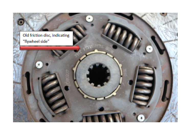
b. Using the provided alignment tool, place the friction disc onto the flywheel. Take note of the markings on the new friction disc, it will indicate “flywheel side” or in this case “transmission side”
c. The alignment tool will hold the new disc in place while we mount the pressure plate over the friction disc, with the alignment tool protruding out the middle
d. Apply thread locker to the 6 bolts, and secure the pressure plate (torque to 24 lb-ft 60 degrees)
e. Mark your territory (and remove the alignment tool)
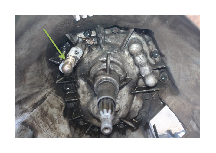
21. Replace the clutch fork, throwout bearing, and pivot stud.
a. Slide the clutch fork down/towards the opening in the bell housing to release the clip connecting to the pivot stud, pull forward and remove. The throwout bearing is attached to the fork and will slide out with it
b. Remove and replace the pivot stud using 7/8” wrench
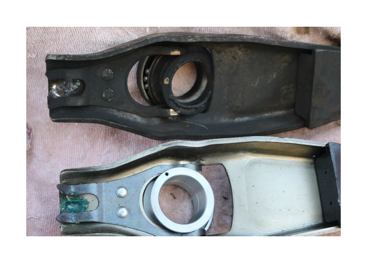
c. Remove and replace the throwout bearing. It will slide in and out of the grooved prongs on the clutch fork
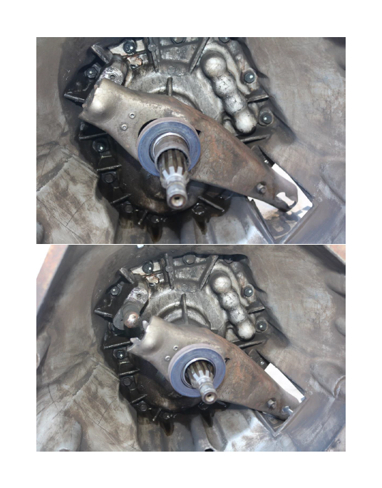
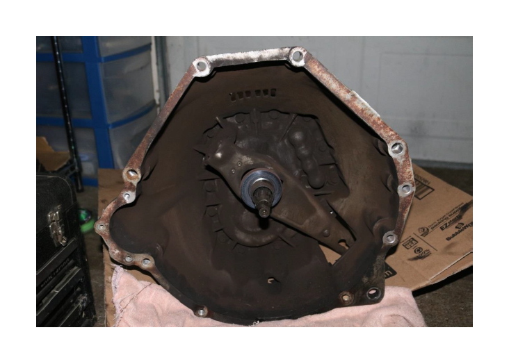
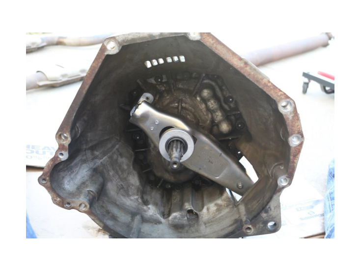
d. Clean the bell housing with Super Clean, or similar degunkifier. Before and after shots:
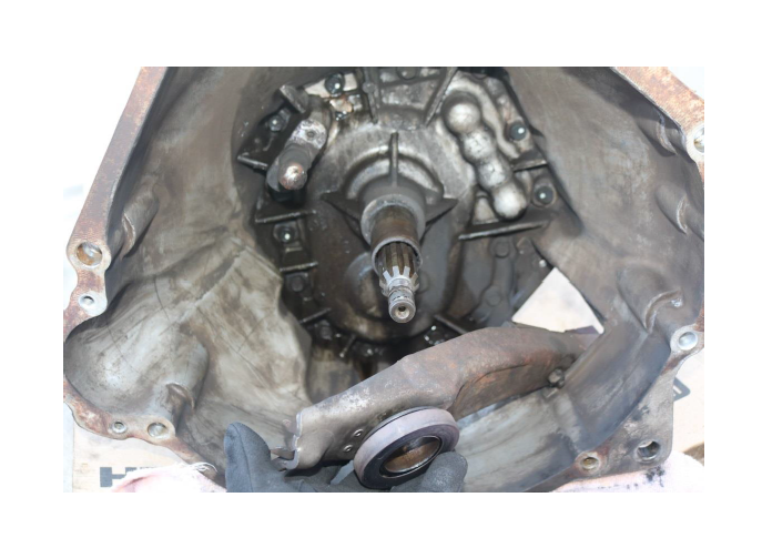
e. Installation of the clutch fork is the reverse of removal. Apply a small amount of grease to the input shaft housing (NOT the grooved input shaft itself) to provide a smoother contact for the new throwout bearing
22. Reinstall the transmission. Note: You can use the clutch fork opening in the bell housing as a viewport to realign the input shaft in through the pressure plate. You may need to turn the input shaft slightly to get the grooves lined up properly with the clutch disc.
a. Make sure the transmission spacer is remounted first. It can hang on the two large holes on either side of TDC, second from the top (reminder, these are the two long bolts)
b. Tie down or secure the loose hanging O2 sensors, clearing the way for the transmission
c. Recall the bolt sizes and pattern from Step 11a and reinstall accordingly
d. 9x 13mm at the bell housing
e. 4x 15mm for the rear transmission mount/crossmember
f. Transmission is now secured, lower the jack and remove
23. Reconnect the clutch cabling and dust cover.
a. Thread the cable through the hole in the spacer/bell housing
b. With no tension on the clutch fork, snake the cable back onto the fork
c. Reinstall the retainer clip on the clutch cable
d. Reinstall the clutch fork dust cover, 1x 10mm
24. Reconnect the reversing lamp switch and the output shaft speed sensor cabling to the transmission.
25. Reinstall the driveshaft.
a. Install the driveshaft yoke into the transmission first, taking care not to damage the internals or shaft
b. Bring the rear of the driveshaft up and onto the differential pinion flange
c. 4x 12mm 12-point socket
d. Apply thread locker and re-torque to 83 lb-ft
26. Reinstall the exhaust, along with the (2) front and (2) rear O2 sensors. Note: To avoid the O2 sensor cabling from getting overly twisted up, counter-twist them before installing to negate most or all of the twist.
a. 8x 15mm (torque to 26 lb-ft at the rear and 30 lb-ft at the manifold)
b. 7/8” wrench for the O2 sensors
27. Reinstall the starter. a. 3x 13mm, the easiest approach is through the front and over the A-arm (torque to 17 lb-ft)
28. Reinstall the front subframe brace.
a. 2x 15mm (torque to 30 lb-ft)
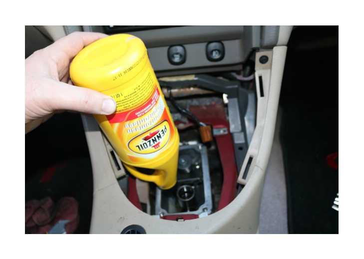
29. Add 3.2 quarts transmission fluid, the easiest method is via the gaping hole where the shifter is currently not. The late ’01 to ’04 GT uses the Tremec TR-3650 transmission, and as per Ford’s TSB 04-15-6 the TR-3650 takes 3 Liters (approximately 3.2 US Quarts).
a. Add via the open/exposed shifter
b. Clean the mating surfaces for the shifter assembly, and apply black RTV to reseal
c. Reassemble the shifter in reverse order of Step 3
30. Check the clutch pedal movement, and make any adjustments as necessary at this time. Also check for any fluid leaks before lowering.
31. Reconnect the battery.
32. Remove the ramps and test drive. Recommended break-in period from Exedy is 750 miles.
Installation Guide Created by AM Customer Ted Hotchkiss on 02/27/2017

