FREE 1 to 3-Day Delivery on Orders $149+ Details
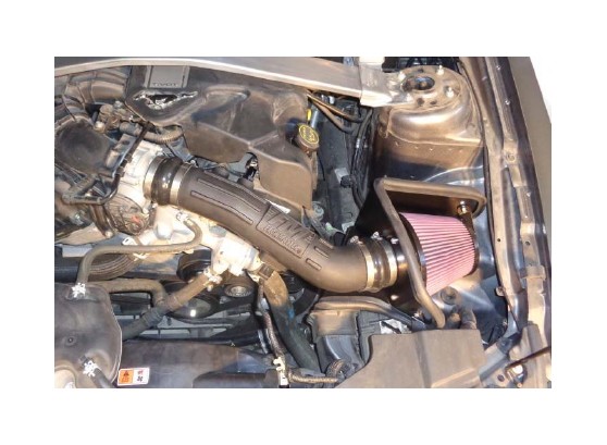
How to Install Flowmaster Delta Force Cold Air Intake (11-14 V6) on your Ford Mustang
REVIEW THE INSTRUCTIONS AND VERIFY KIT CONTENTS:
1. Please take a moment to read and understand these instructions before installing your FLOWMASTER cold air intake kit.
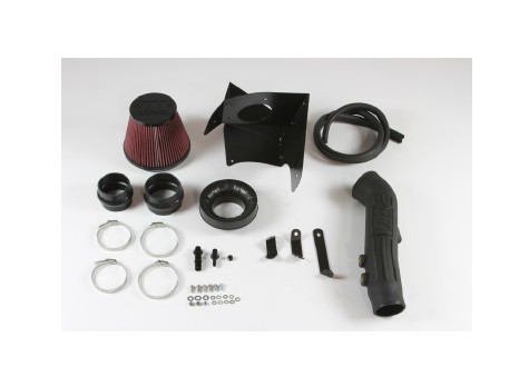
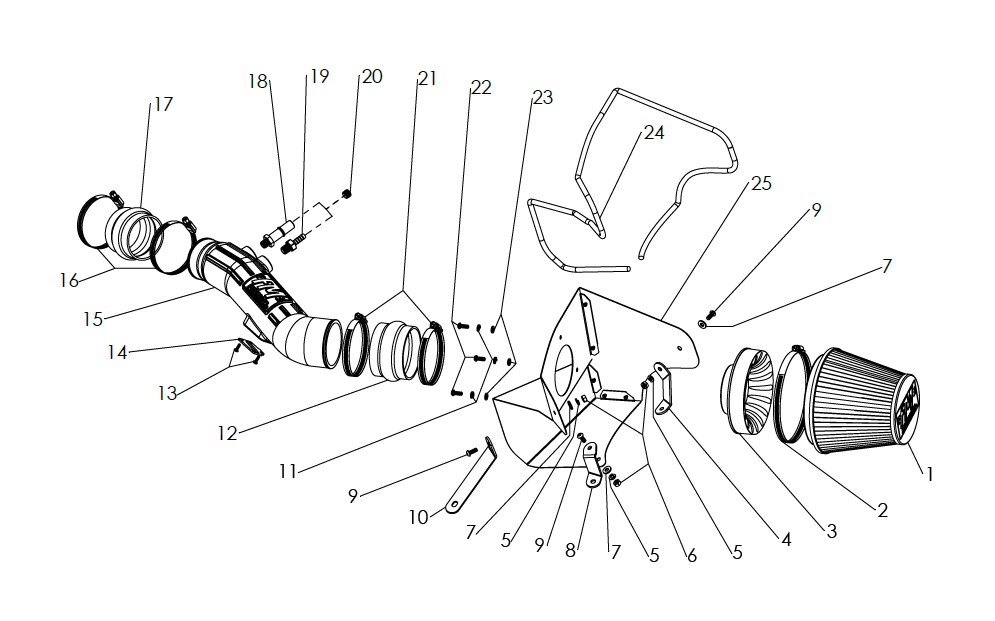
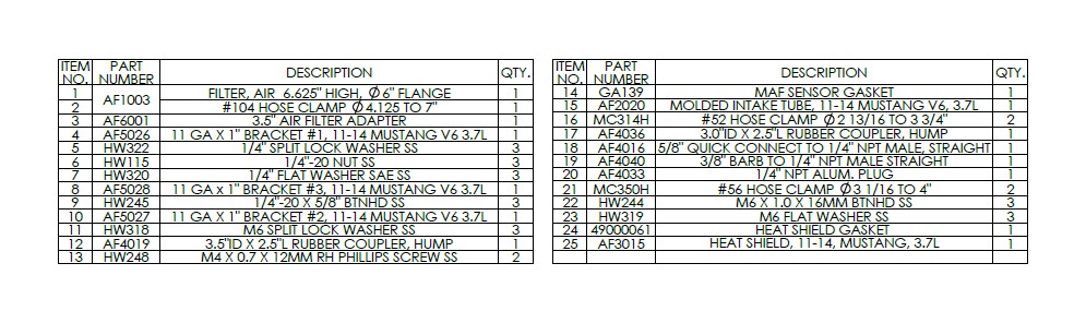
2. Use the parts drawing and list (front page) to verify your kit’s contents.
In the unlikely event that any parts are missing, please contact FLOWMASTER Technical Support for replacements.
To simplify assembly and avoid cross‐threading fasteners , identify and separate the ¼‐20 screws, item (9) (used with nuts (6)), and the M6 screws (22) (used with filter adapter (3)).
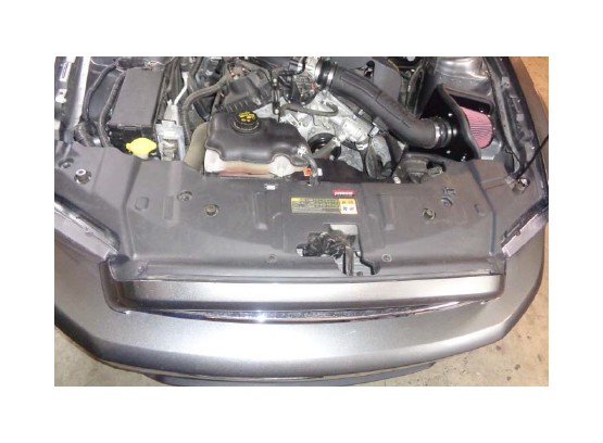
REMOVE FACTORY AIR INTAKE SYSTEM:
NOTES
• We highly recommend that you retain all factory air intake system parts.
• Please refer to vehicle manufacturer’s recommendations regarding removal of factory components.
• Disconnecting the negative battery cable erases pre‐programmed electronic memories. Write down all memory settings before disconnecting the negative battery cable. Some radios will require an anti‐theft code to be entered after the battery is reconnected. The anti‐theft code is typically supplied with your owner’s manual. In the event your vehicle’s anti‐theft code cannot be recovered, contact an authorized dealership to obtain it.
3. Turn off the vehicle’s ignition and disconnect the negative battery cable.
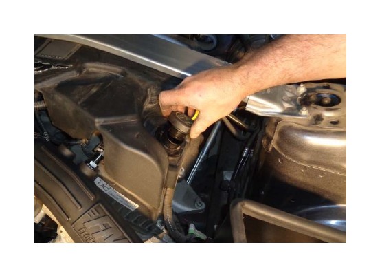
4. If your vehicle includes the optional engine cover, provide working clearance around the cover by removing the oil fill cap and fill cap extension, then temporarily reinstalling the fill cap.
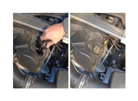
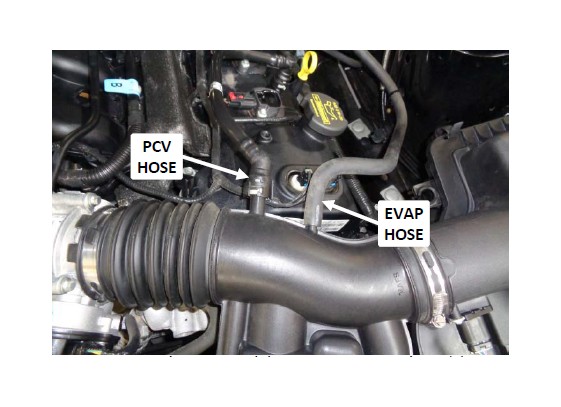
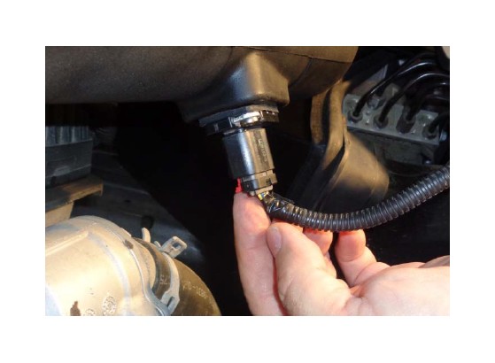
5. Remove the PCV and / or EVAP vacuum hose(s) from the intake duct. (Your vehicle may have either / both hoses.) NOTE: Release the PCV fitting by lifting the latch up and to the left.
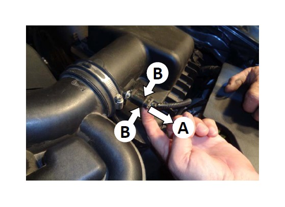
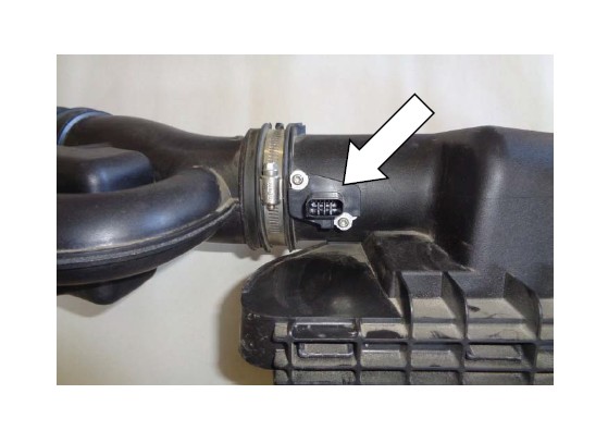
6. Disconnect the mass airflow (MAF) sensor plug by (A) pulling the locking tab away from the sensor until it stops, then (B) squeezing the flat sides of the plug and pulling it straight off the sensor.
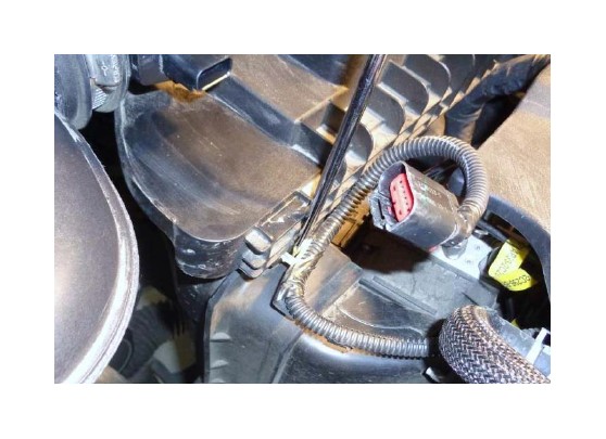
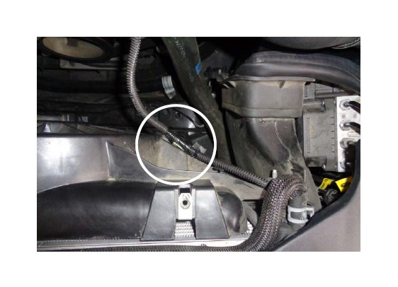
7. Use a flat‐tip screwdriver to release the clip securing the MAF lead to the airbox.
8. Remove and retain the airbox mount bolt.
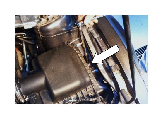
9. Loosen the hose clamp securing the intake duct to the throttle body, and remove the duct from the throttle body.
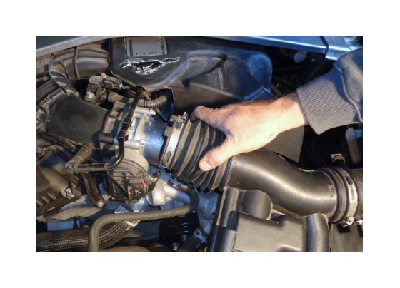
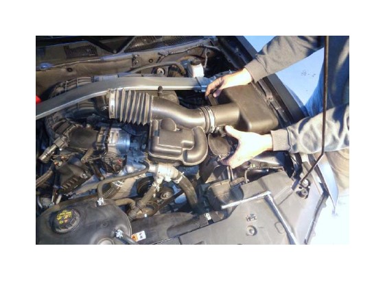
10.Remove the assembled airbox and duct from the vehicle.
11.Remove the MAF sensor from the airbox, then remove the stock gasket from the sensor. CAUTION: The sensor is delicate! Handle it with care, and store it in a safe location until reinstallation.
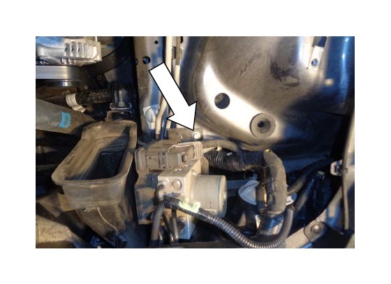
12.Remove and retain the lower mount bolt.
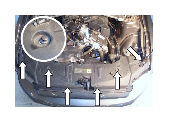
13.Use a flat‐tip screwdriver to release the 6 radiator support cover fasteners at the locations shown. Remove the fasteners, then remove the cover.
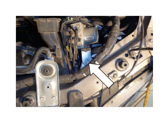
14.Remove and retain the upper mount bolt (hidden behind the cable bundle).
ASSEMBLE AND INSTALL YOUR FLOWMASTER COLD AIR INTAKE SYSTEM:
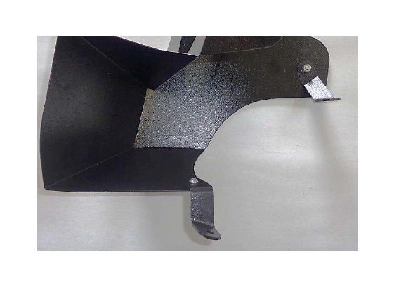
15. Attach bracket (10) to heat shield (25) using ¼‐20 × 5/8" screw (9) (against bracket) and flat washer (7), lock washer (5) and nut (6) (against heat shield).
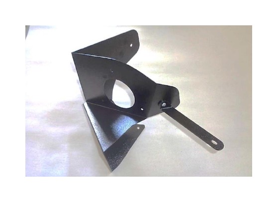
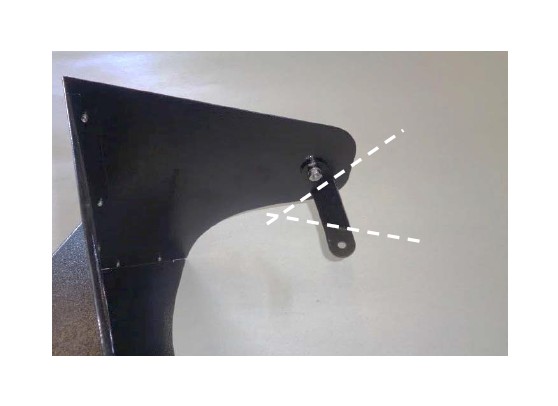
16.Attach bracket (4) to heat shield using ¼‐20 × 5/8" screw (9) and flat washer (7) (against heat shield), and lock washer (5) and nut (6) (against bracket). Note orientation of bracket bend lines.
17.Attach bracket (8) to heat shield using ¼‐20 × 5/8" screw (9) (against bracket), and flat washer (7), lock washer (5) and nut (6) (against heat shield).
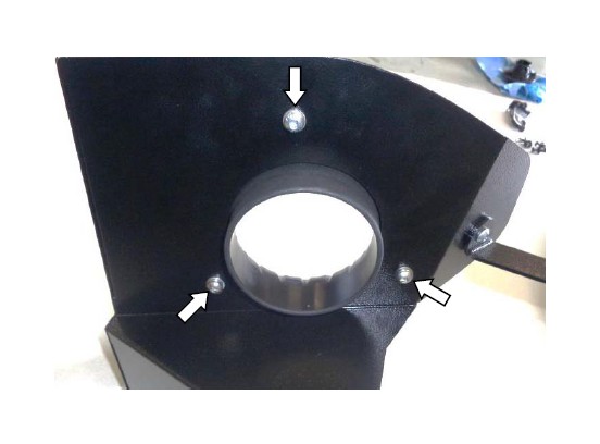
18.Assemble air filter adapter (3) to heat shield using M6 screws (22), lock washers (11) and flat washers (23).
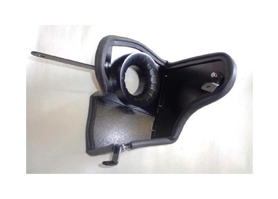
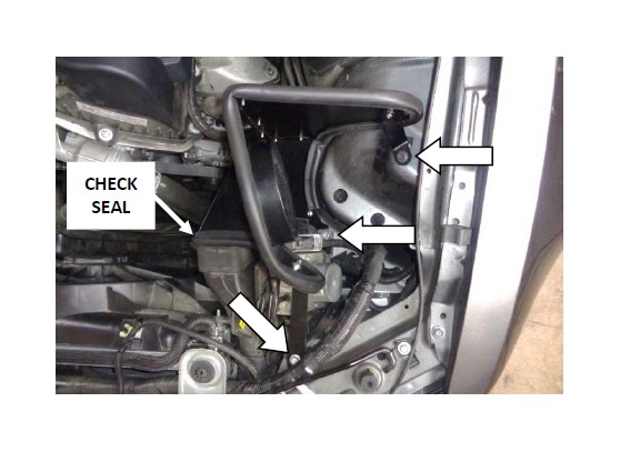
19.Attach the gasket (24) to the heat shield. Starting on either side of bracket (8), gradually work around the heat shield, firmly pressing the seal onto the edge. When you return to the bracket, trim seal to fit using metal‐cutting shears.
20.Install heat shield in vehicle, securing the brackets with the factory bolts removed earlier. If necessary, adjust alignment of the brackets, then retighten their fasteners. Verify even contact between heat shield gasket and lip seal on stock air duct.
21. Determine which vacuum fitting(s) are required for your vehicle’s configuration. The 5/8" quick disconnect fitting (18) mates with the PCV hose latching connector. The 3/8" barbed fitting (19) mates with the EVAP system hose.
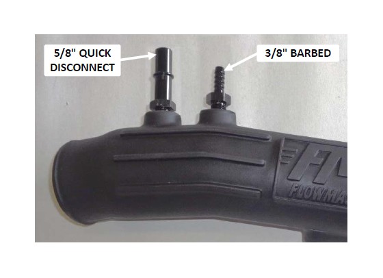
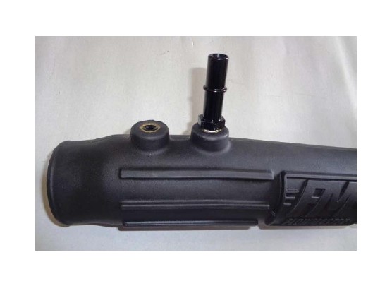
22.Your vehicle may require one or both vacuum fittings. If it uses only one fitting, the 1/4" plug (20) will be fill the unused port. Apply 2 wraps of nylon thread tape to threads of the required hardware, and install them in intake tube (15), in the appropriate ports.
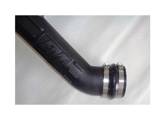
23.Install two small hose clamps (16) on small flex coupler (17), and install coupler on discharge end of intake tube. Only snug the clamps at this time, to allow adjustment when tube is installed.
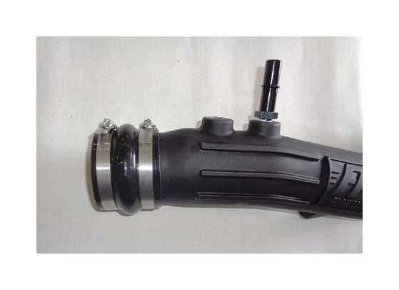
24.Install two large hose clamps (21) on large flex coupler (12), and install coupler on intake end of intake tube. Only snug the clamps at this time, to allow adjustment when tube is installed.
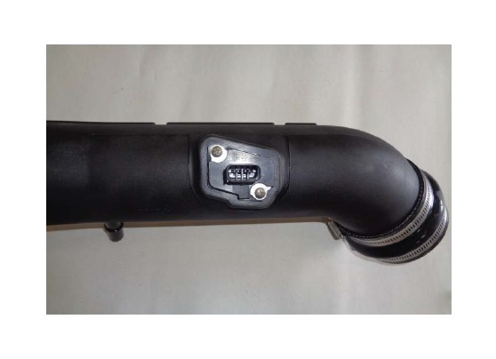
25.Slip the MAF sensor gasket (14) over the sensor, ensuring correct orientation. Then install the sensor in intake tube, using M4 screws (13).
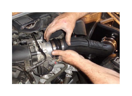
26.It is recommended that the assembled intake tube be installed as follows. First, install the right coupler on the filter adapter.
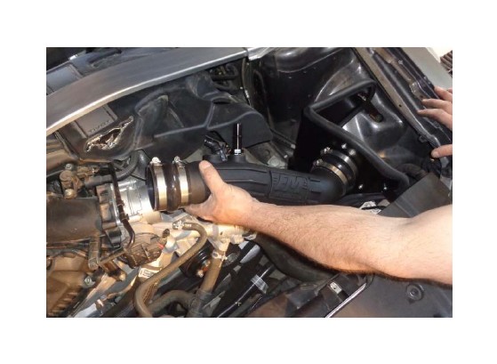
27.Then connect the vacuum hose(s) to their respective fitting(s).
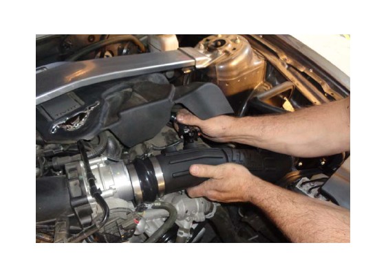
28.Install the left coupler on the throttle body.
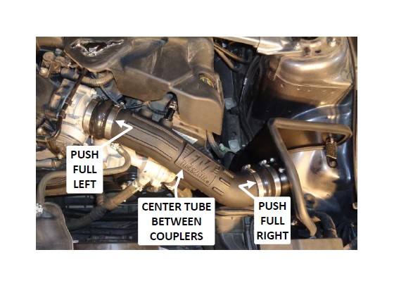
29.Push the left coupler up against the raised stop on the throttle body. Push the right coupler up against the heat shield. Then center the intake tube between the couplers, and tighten all hose clamps.
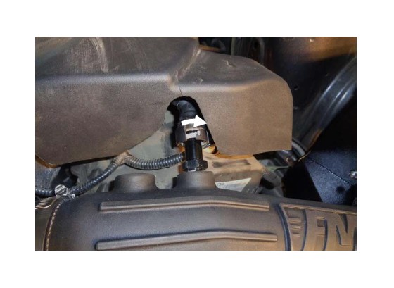
30.If your vehicle has a latching PCV fitting, secure it by pushing the latch to the right until it clicks.
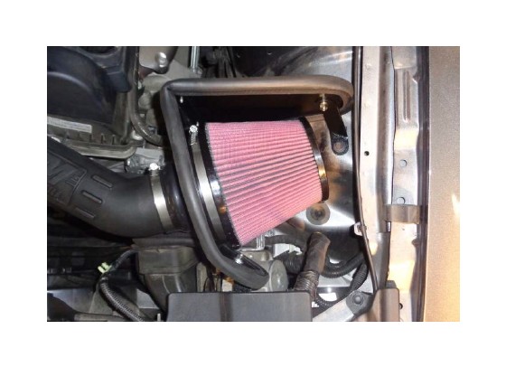
31.Install clamp (2) on air filter (1), then install filter on filter adapter and tighten clamp.
32.Plug the MAF sensor lead into the sensor, push the latch in, and verify the connector is secure.
33.Secure the loose MAF sensor lead away from any moving parts, using the factory clip or cable ties.
34.If your vehicle includes the optional engine cover, remove the oil fill cap, reinstall the fill cap extension (removed at Step 4), then reinstall the fill cap.
35.Reinstall the radiator support cover and secure with the 6 fasteners (removed at Step 13).
Congratulations, the installation of your FLOWMASTER cold air intake kit is now complete!