 FREE 1 to 3-Day Delivery on Orders $149+ Details
How to Install Ford Performance Performance Pack Front Control Arm Kit on your Mustang
Installation Time
3 hours
Tools Required
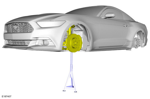
- Vehicle/Axe Stands
- Mechanics' Hand Tools
- Lower Arm Ball Joint Seperator

Shop Parts in this Guide
Frontward Lower Arm removal
Special Tool(s) / General Equipment
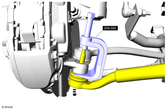
- 204-592 Separator, Lower Arm Ball Joint
- Vehicle/Axle Stands

Lower Arm Ball Joint Seperator
Removal
NOTICE: Suspension fasteners are critical parts that affect the performance of vital components and systems. Failure of these fasteners may result in major service expense. Use the same or equivalent parts if replacement is necessary. Do not use a replacement part of lesser quality or substitute design. Tighten fasteners as specified.
Remove the wheel and tire.
NOTICE: The front suspension height sensor must be disconnected from the lower control arm prior to servicing suspension components or damage to the suspension height sensor and/or the vehicle dynamic suspension system may occur. The sensor will need to be recalibrated after reassembly.
NOTE: If equipped with dynamic suspension.
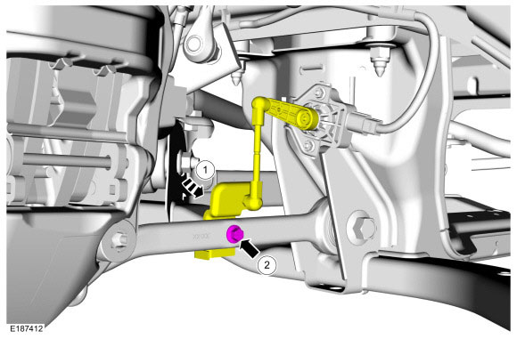
1. Remove the ride height sensor arm bracket bolt.
2. Position the ride height sensor arm bracket aside.

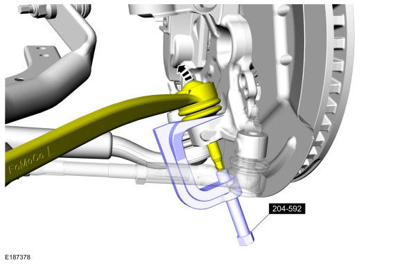
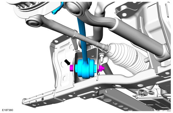
NOTICE: Do not use a prying device or separator fork between the ball joint and the wheel knuckle. Damage to the ball joint or ball joint seal may result. Only use the pry bar by inserting it into the lower arm body opening.
NOTICE: Use care when releasing the lower arm and wheel knuckle into the resting position or damage to the ball joint seal may occur.
Separate the front lower arm from the wheel spindle.
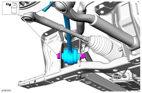
Remove and discard the front lower arm-to-frame bolt and remove the front lower arm.
Installation
NOTE: Only tighten the bolt finger tight at this stage.
Position the front lower arm and install the new front lower arm-to-frame bolt.

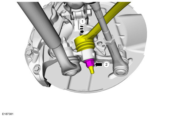
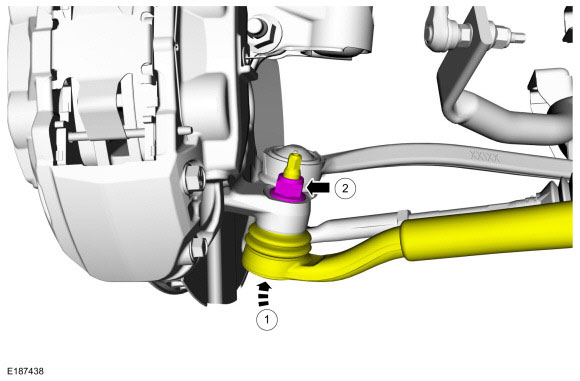
1. Attach the front lower arm to the wheel spindle.
2. Install the new front lower arm outboard nut. Torque: Non SVT: 85 lb.ft (115 Nm)
Rearward Lower Control Arm removal
Remove and discard the rear lower arm outboard nut.
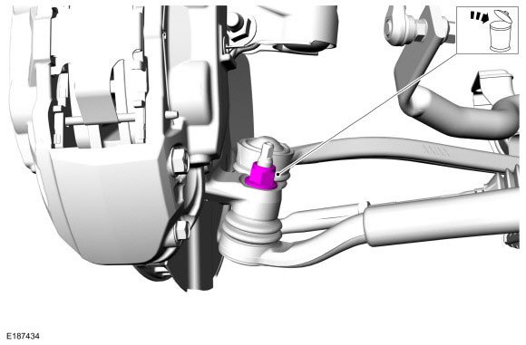
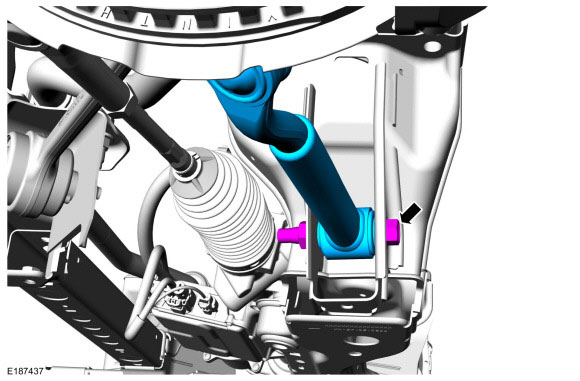
NOTICE: Do not use a prying device or separator fork between the ball joint and the wheel knuckle. Damage to the ball joint or ball joint seal may result. Only use the pry bar by inserting it into the lower arm body opening.
NOTICE: Use care when releasing the lower arm and wheel knuckle into the resting position or damage to the ball joint seal may occur.
Separate the rear lower arm from the wheel spindle.
Remove and discard the rear lower arm-to-frame bolt and remove the rear lower arm.

Installation
NOTE: Only tighten the bolt finger tight at this stage.
Position the rear lower arm and install the new rear lower arm-to-frame bolt.

1. Attach the rear lower arm to the wheel spindle.
2. Install the new rear lower arm outboard nut.
Torque:
Non SVT: 85 lb.ft (115 Nm)
Support the suspension at curb height.
Use the General Equipment: Vehicle/Axle Stands
NOTICE: Tighten the suspension bushing fasteners with the suspension loaded or with the weight of the vehicle resting on the wheels and tires, otherwise incorrect clamp load and bushing damage may occur.
Tighten the rear lower arm-to-frame bolt.
Torque: 184 lb.ft (250 Nm)
Tighten the front lower arm-to-frame bolt.
Torque: 184 lb.ft (250 Nm)
NOTE: If equipped with dynamic suspension.
1. Position the ride height sensor arm bracket.
2. Install the ride height sensor arm bracket bolt.
Torque: 177 lb.in (20 Nm)
Install the wheel and tire.
Installation
WARNING: When a wheel is installed, always remove any corrosion, dirt or foreign material present on the mounting surface of the wheel and the mounting surface of the wheel hub, brake drum or brake disc. Make sure that any fasteners that attach the rotor to the hub are secured so they do not interfere with the mounting surfaces of the wheel. Failure to follow these instructions when installing wheels may result in the wheel nuts loosening and the wheel coming off while the vehicle is in motion, which could result in loss of control, leading to serious injury or death to vehicle occupant(s).
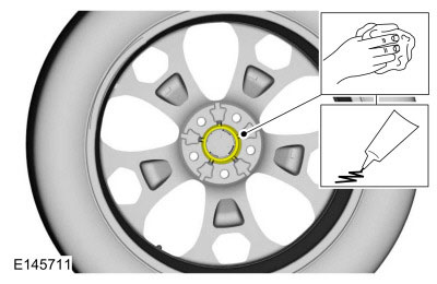
NOTICE: Make sure to apply a thin coat of anti-seize lubricant only to the interface between the wheel pilot bore and the hub pilot. Do not allow the anti-seize to make contact with the wheel-to-brake disc/drum mounting surface, wheel studs, wheel nuts, brake pads or brake disc friction surfaces or damage to components may occur.
Clean the mounting surface of the wheel. Apply the substance from the specified tube.
Material: High Temperature Nickel Anti-Seize Lubricant / XL-2
NOTE: Only tighten the nuts finger tight at this stage.
Position the wheel and install the wheel nuts.
WARNING: Retighten wheel nuts within 160 km (100 mi) after a wheel is reinstalled. Wheels can loosen after initial tightening. Failure to follow this instruction may result in serious injury to vehicle occupant(s).
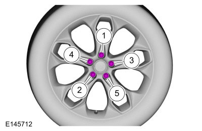
NOTICE: Failure to tighten the wheel nuts in a star/cross pattern can result in high brake disc runout, which accelerates the development of brake roughness, shudder and vibration.
NOTE: The wheel nut torque specification is for clean, dry wheel stud and wheel nut threads.
NOTE: Final tightening to be performed with vehicle resting on tires.
Tighten the wheel nuts in a star pattern.
Torque: 148 lb.ft (200 Nm)
Check and if necessary adjust front toe.
If equipped with dynamic suspension, calibrate the suspension system. Connect the scan tool and carry out the Ride Height Calibration routine. Follow the scan tool directions.

