FREE 1 to 3-Day Delivery on Orders $149+ Details
Ford Racing 1.7 Performance Roller Rockers - Stud Mount (289/302/5.0L/351W) - Installation Instructi
Installation
Install
1. Place the rocker arm on the stud with the flat side of the fulcrum turned up.
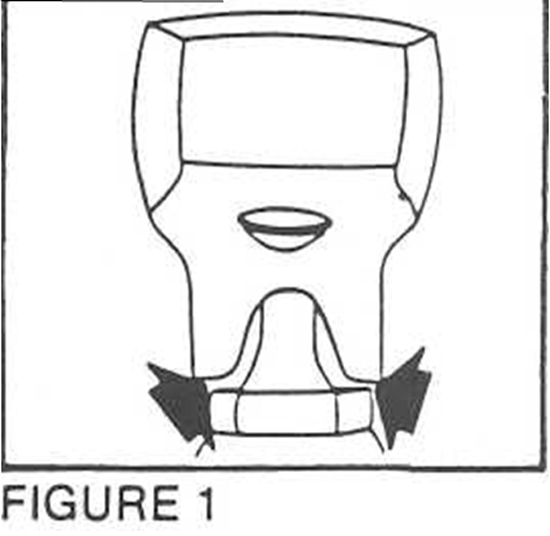
2. Check to insure that the bottom side of the rocker arm does not contact the lower portion of the rocker arm stud, or the stud boss, when the lifter is on the base circle, which is the lowest point of the cam. See Figure 1. Installation of a longer than stock length pushrod will increase the clearance in this area.
3. Check to insure there is no contact between the underside of the rocker arm and the valve spring and retainer assembly. Normally, the least clearance occur when the valve is closed and the lifter is on the base circle, which is the lowest point of the cam, but you should check it throughout its travel after you adjust the valves (see step 4).
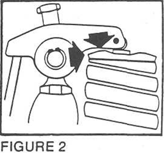
4. We offer certain rocker arms that are machined to offer additional clearance when used with large diameter valve springs. DO NOT ATTEMPT TO GET PROPER CLEARANCE BY GRINDING OR MODIFYING THE ROCKER ARM! We recommend a minimum of.040" clearance in the area marked in Figure 2. Additional clearance can be gained by using a longer than stock push-rod. Remember to recheck your rocker arm geometry.
5. Valve adjustment—make sure the pushrod is in the tappet and in the rocker arm seat when adjusting.
6. For hydraulic lifter adjustment, turn the engine in the normal direction of rotation until the exhaust lifter starts to move up, then adjust the intake valve to zero lash with no pre-load, then Y2 turn more. You adjust the valve by rotating the hexnut until you obtain the proper adjustment, tighten the set screw, then torque the hex nut to 15-20 ft pounds maximum. Next, turn the engine again in the normal direction until the intake valve opens and then is almost closed. Now set the exhaust valve to zero lash, then V2 turn more, locking the nut as described above. Continue the procedure for each cylinder until all valves are adjusted.
7. For mechanical lifter adjustment, use the same procedure except instead of lifter pre-load, you must use the clearance specs on your camshaft specification card. Re-check the adjustment after the hex nut is torqued.
Installation instructions provided by Manufacturer