FREE 1 to 3-Day Delivery on Orders $149+ Details
How to Install a Ford Racing Voltmeter Gauge on your 1979-2013 Mustang
Installation
CAUTION FOR ALL GAUGE INSTALLATION
As a safety precaution, the 12V wire attached to the positive I ( ) terminal of t~e gauge sho~ld be fused. before connecting to the positiye ( ) output side of the ignition switch. We recommend using ~ 4 Amp, 3 AG fast-acting type cartndge fuse (Llttlefuse® # 312 004 or an equivalent) inline between the power supply source and the I ( ) terminal on the gauge.
NOTE: Some late model vehicles use electronic sensors in their pressure and temperature senders for engine control functions. Before removing the original sender, we recommend that you contact your automotive dealer to be sure no critical functions will be disrupted . . With pressure gauges it is beneficial to add a T-fitting to install your new gauge and to keep the warning light operational. This allows you to monitor the pressure and still have a warning light to indicate emergency conditions.
NOTE:: Disconnect negative (-) battery cable before installation.
CAUTION: Do not touch ignition wire to the sender (5) terminal on back of gauge or the sender may be damaged.
Mounting
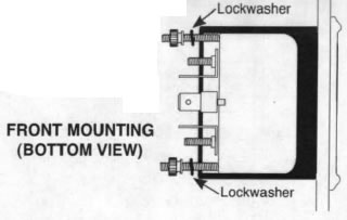
These gauges can be mounted in-dash or in Auto Meter mounting solutions (panels, cups, pods, etc.). 2 1/16" diameter gauges mount in 2 1/16" hole. Fasten with brackets supplied as shown. (Hookup wire is required.) To assure proper functioning of this instrument, please read instructions thoroughly before installing.
Metric Adapters
If this product is to be installed on a vehicle requiring metric fittings, please contact your local Auto Meter dealer to purchase metric adapters. A complete listing of the fittings available can be found in our catalog or online at http ://www.autometer.com
Temperature Gauges
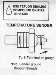
1. Install temperature sender.
- Water Temp: Install temperature sender (included). Purchase of additional fittings such as metric or hose adapters may be required.
- Oil & Trans. Temp: Hole may have to be drilled and adapter nut (included) welded or brazed in pan. Be sure there is adequate internal clearance for nut and sender. Sender needs to be threaded into something that is grounded. If not, proper ground connections need to be made. May use #2260 weld on bung on steel pans (not included).
- Cylinder Head Temp: Head must be drilled and tapped for ""8" NPT hole. Sender needs to be threaded into something that is grounded. If not, proper ground connections need to be made. Be sure not to drill all the way through.
- Diff. Temp: Install temperature sender in ""8" NPT sender port on cover if available. If cover does not have a port, remove cover and drill and tap a ""8" NPT hole or, drill and weld, or braze, adapter nut (included) in cover. Proper ground connections should be made by running ground wire from bolt in cover to chassis, being sure to leave enough slack in wire for suspension travel.
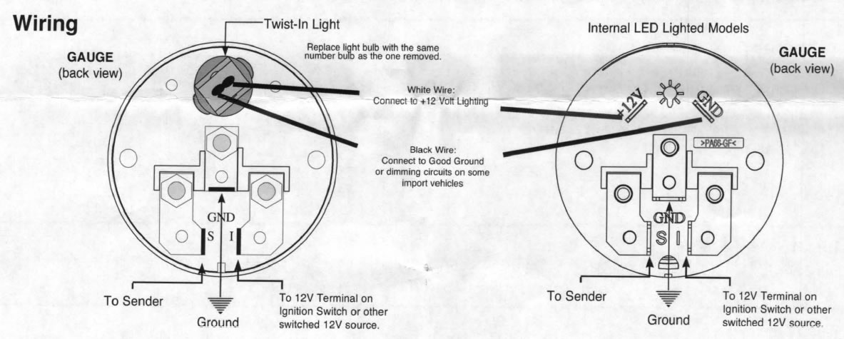
2. Route 18-gauge wire through firewall. If a new hole is drilled in the firewall a grommet is recommended. Connect one end to terminal post on temperature sender, and opposite end to sender (S) terminal on back of gauge.
3. Route 18-gauge wire from center terminal GND (-) on back of gauge to good ground near sender.
4. Connect wire from ignition switch to ignition (I) terminal on back of gauge.
5. Reconnect negative (-) battery cable.