FREE 1 to 3-Day Delivery on Orders $149+ Details
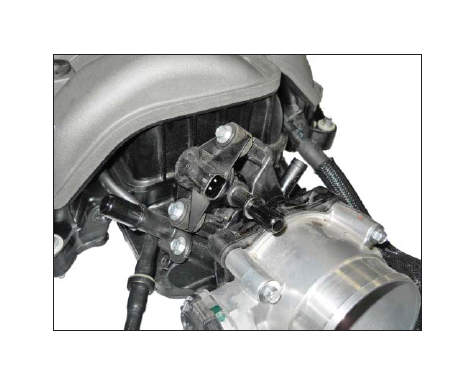
How to Install a 670HP Mustang Supercharger Kit - Manual on your 2015 GT Mustang
SECTION A – DISASSEMBLY
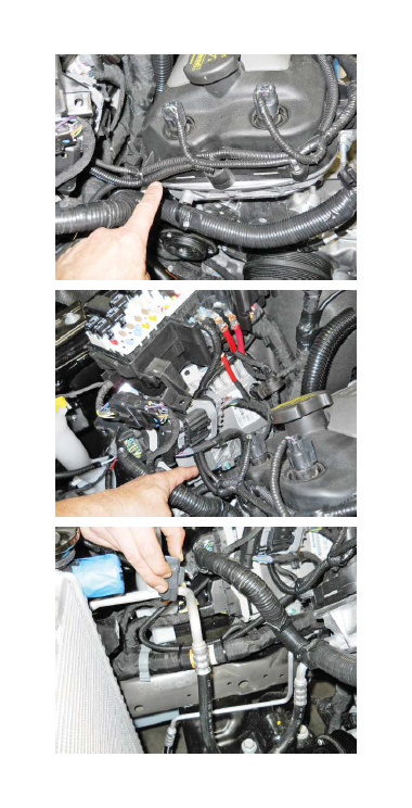
The following section will guide you through the disassembly of the stock components. Special care should be taken to label fasteners and parts that are taken off during this procedure since many will be reused:
1. Cover both fenders with fender covers to protect the vehicle finish.
2. Release the fuel system pressure.
NOTE: The following procedure is taken directly from the Ford Service Manual).
WARNING: Fuel in the fuel system remains under high pressure even when the engine is not running. Before working on or disconnecting any of the fuel lines or fuel system components, the fuel system pressure must be relieved. Failure to do so can result in personal injury.
WARNING: flame of any type when working on or near any fuel-related components. Highly flammable mixtures are always present and can be ignited, resulting in personal injury.
a. Open the vehicle doors and lift the bottom cushion of the back seat. It is held in place by a push tab in the center of each cushion.
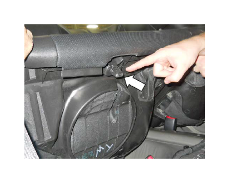
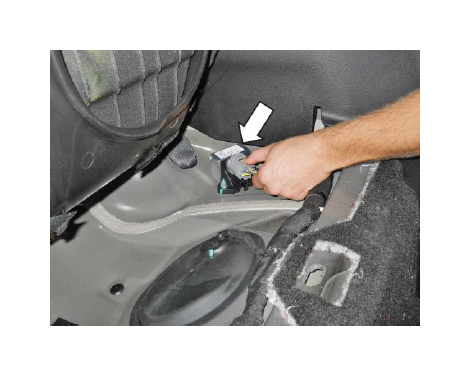
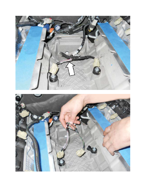
b. Disconnect the Fuel Pump Control Module electrical connector located under the driver side back seat.
c. Start the engine and allow it to idle until it stalls.
d. After the engine stalls, crank the engine for approximately 10 seconds to make sure the fuel injector supply manifold pressure has been released.
e. Turn the ignition switch to the OFF position.
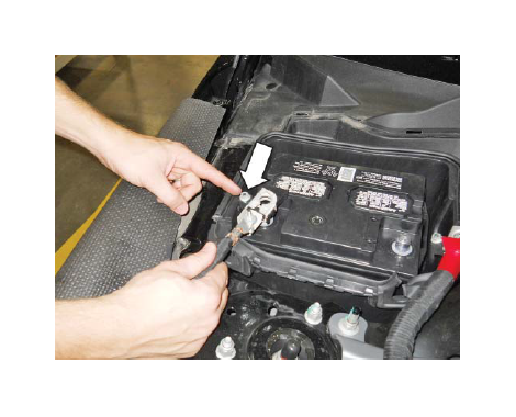
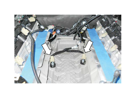
3. Open the hood. Remove the push pins from the battery cover panel located on the passenger side of the engine bay, and remove the panel.
4. Loosen the retaining nuts and disconnect the (-) negative and ( ) positive connections to the battery. Stow the cables out of the way.
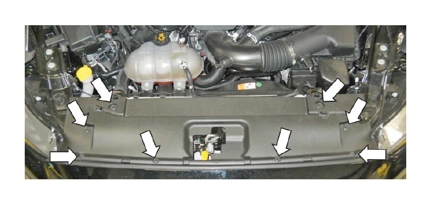
5. Release the (8) push pin retainers by pulling the center pin and remove the radiator trim cover.
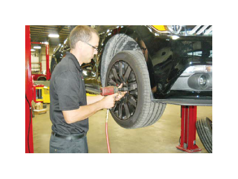
6. Raise the front of the vehicle using the Ford recommended lifting points and place onto safety stands. With the tires lifted off of the ground, remove the front wheels.
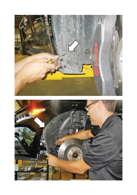
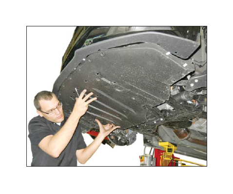
7. Note the position of the fourteen (14) small, medium and large pushpins on the inner wheel well splash shields so they can be reinstalled in the same position. Remove the pushpins then remove the inner wheel well splash shields.
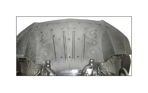
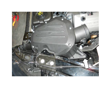
8. Remove the nineteen (19) lower close-out panel bolts and the two (2) pushpins. Remove the lower close-out panel from the vehicle (7 mm socket).
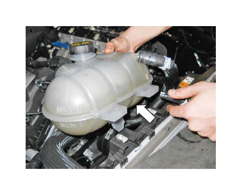
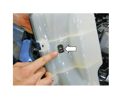
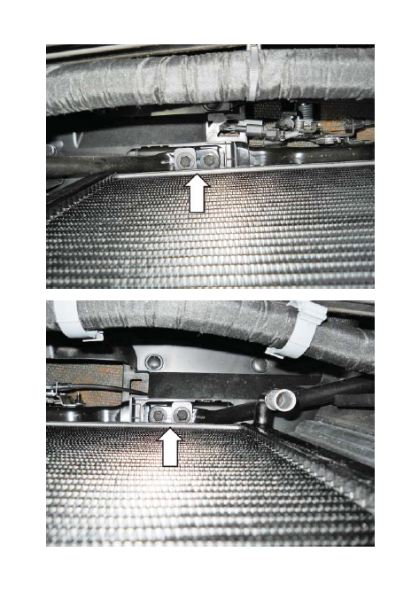
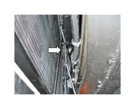
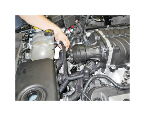
9. With the engine cool, remove the cap on the engine coolant degas bottle and drain the coolant using the petcock located on the lower passenger side of the radiator. Save the coolant for reuse.
Tip: Connect a 3/8" hose to the drain fitting next to the petcock and run into a clean drain pan or bottle. Use a 3/4" wrench to open petcock and allow coolant to drain out of the fitting.
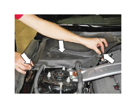
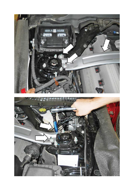
10. If equipped, remove the four (4) nuts and the strut tower cross brace (15 mm socket). The strut tower cross brace cannot be reused after the supercharger has been installed. Discard the nuts.
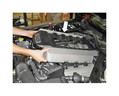
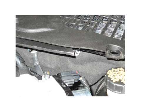
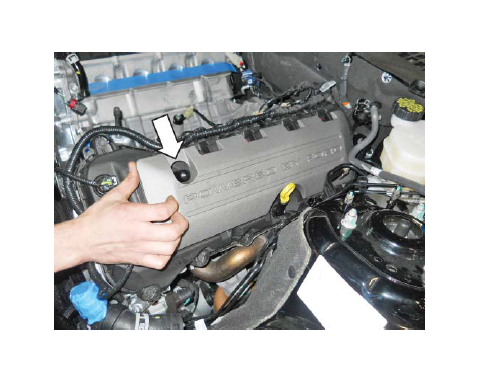
11. Lift up and remove the engine appearance
cover. The cover cannot be reused after the supercharger has been installed.
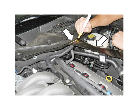
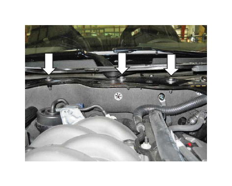
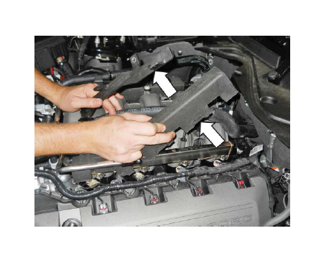
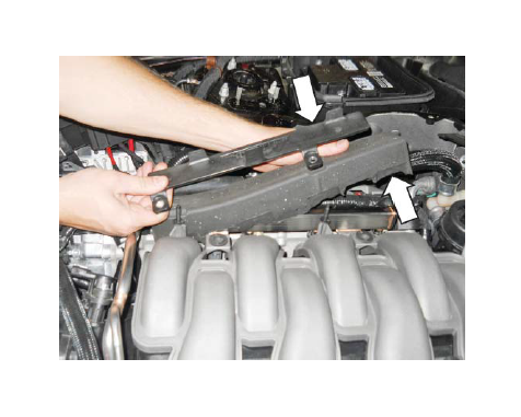
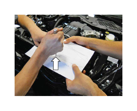
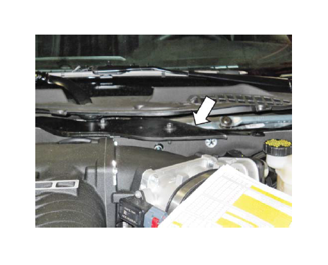
12. Mark a cut line on the LH side of the K-brace using the wiper cowl as a guide as shown. Remove the six (6) pushpin retainers on the cowl trim panel. Lift up the cowl trim panel and remove the two (2) nuts and five (5) bolts from the K-brace. Slide the K-brace out from the cowl trim panel and remove it from the vehicle.
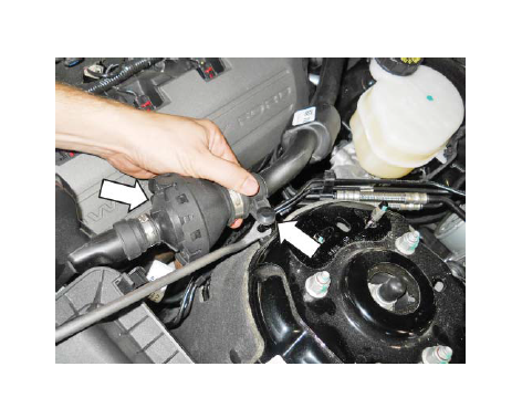
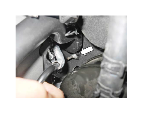
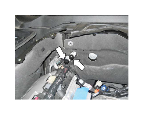
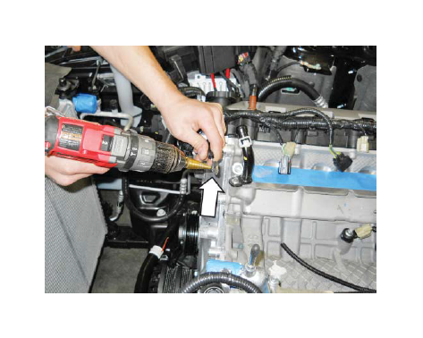
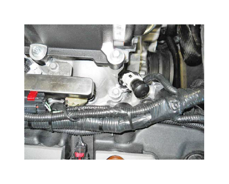
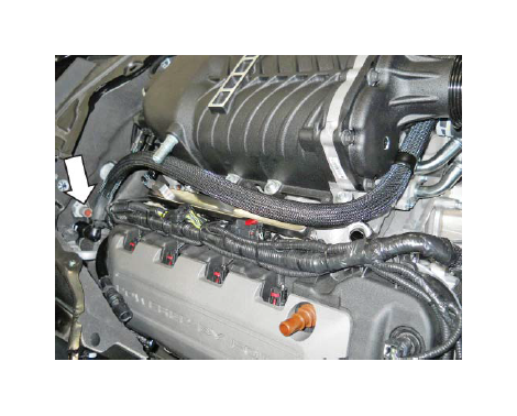
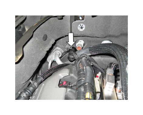
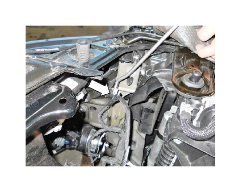
13. Pry up the pushpin securing the induction resonance tube to the strut tower. Remove the mounting nut at the base of the induction resonance tube at the firewall (10 mm). If necessary, remove the dipstick to gain access to the nut. Remove the induction resonance tube from the cowl. The induction resonance tube will not be reused.
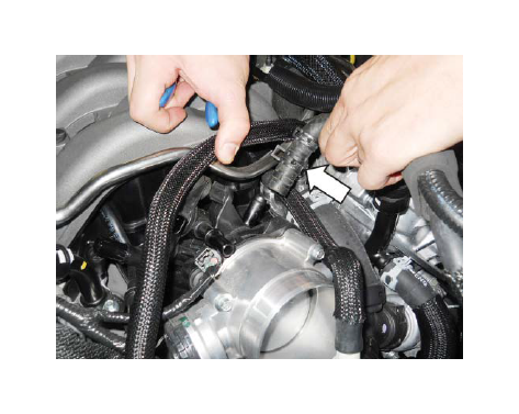
14. Disconnect the brake aspirator line from the clean air tube.
15. Disconnect the vacuum line from the air cleaner tube.
16. Disconnect the positive crankcase ventilation (PCV) tube from the clean air tube.
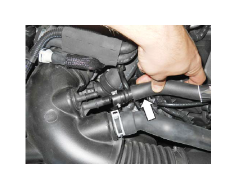
17. Disconnect the PCV Fresh Air Inlet tube from the left-hand cam cover and remove the tube from the vehicle.
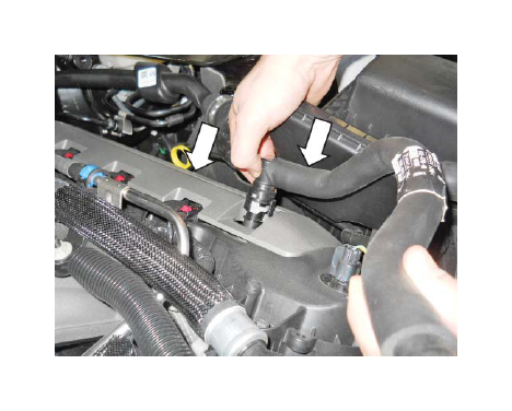
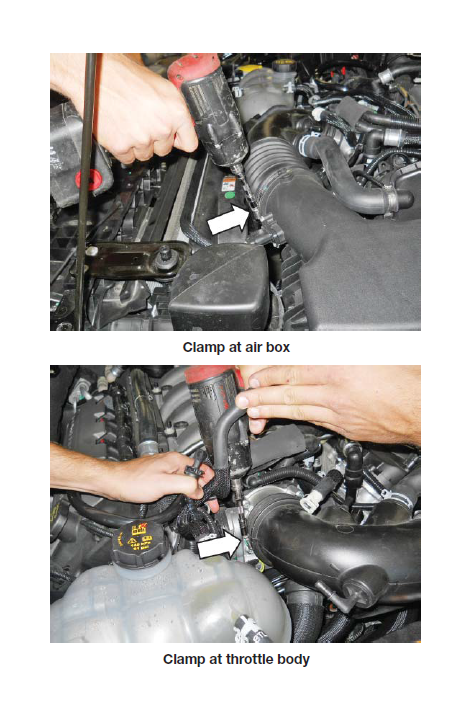
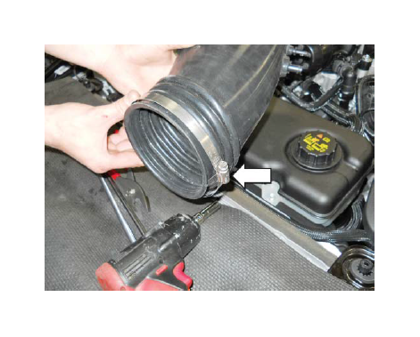
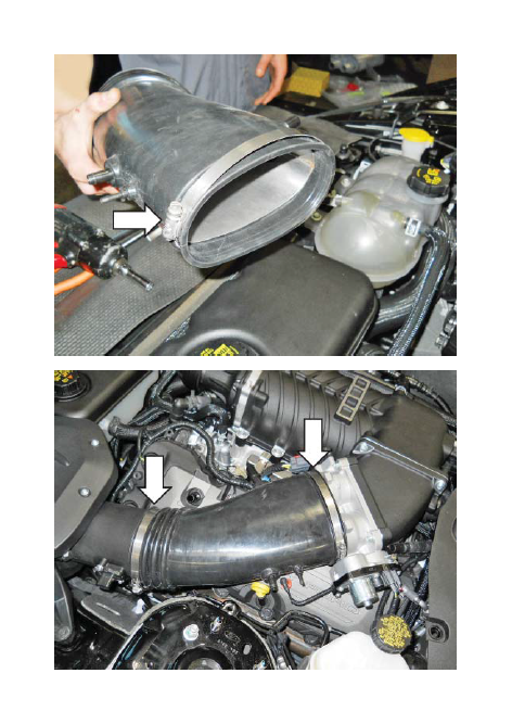
18. Loosen the clamps securing the clean air tube at the airbox and throttle body. Remove the clean air tube from the throttle body and airbox lid. The clean air tube will not be reused.
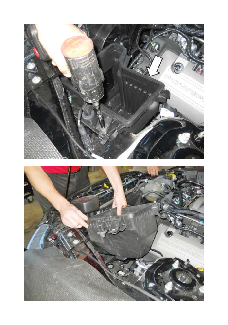
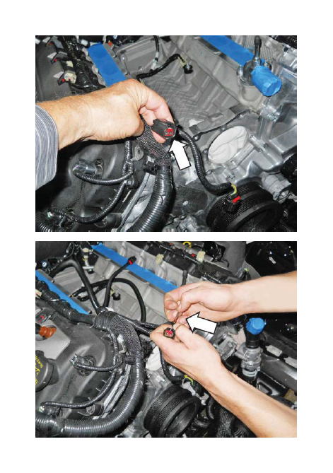
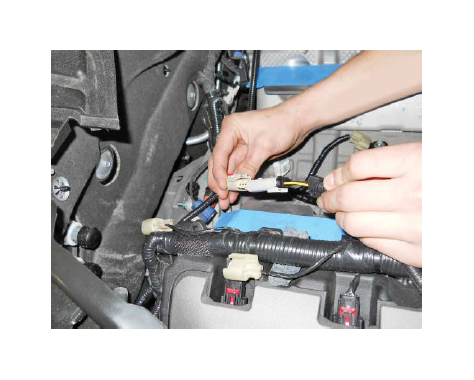
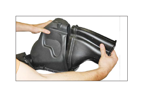
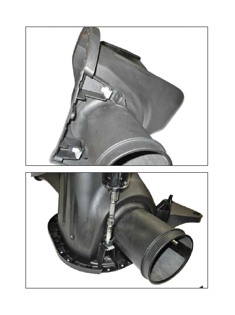
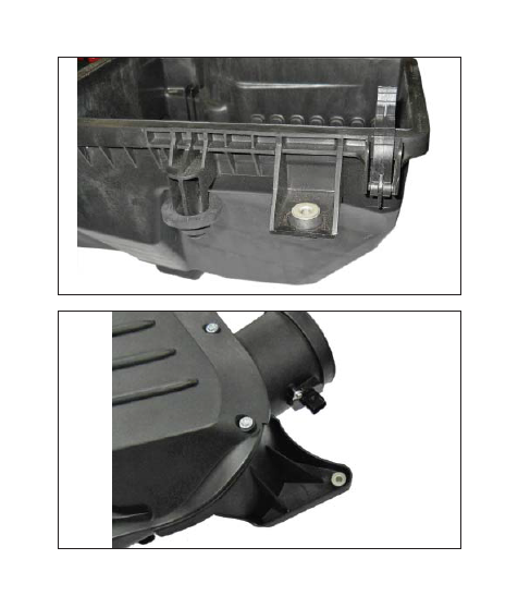
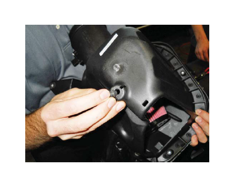
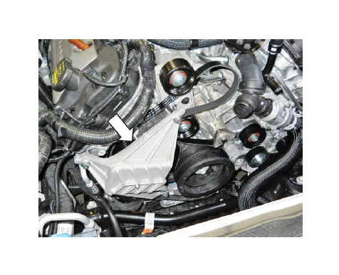
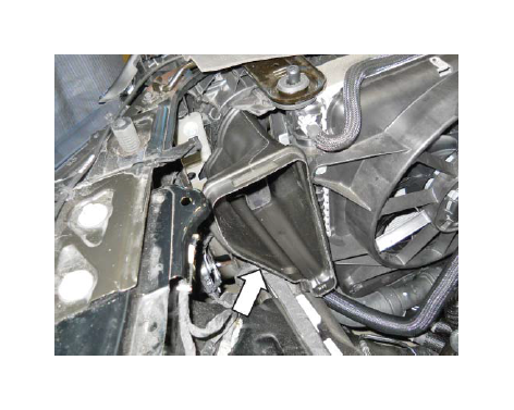
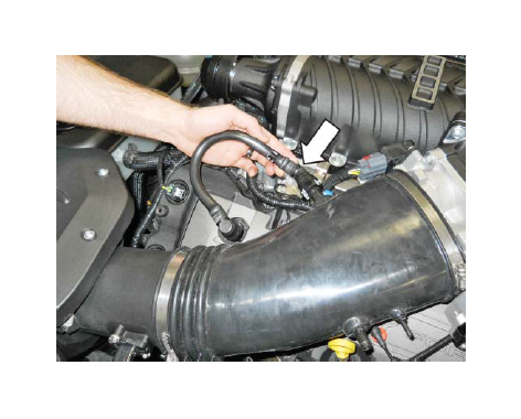
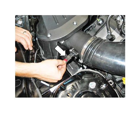
19. Remove the MAF (mass air flow) sensor connector by pulling the red locking tab back and pressing the black release tab. Release the two (2) locking tabs securing the upper airbox lid to the lower airbox. Disconnect the MAF wiring harness retainer from the front edge of the upper airbox lid. Remove the lid from the vehicle and set it aside. The MAF sensor will be reused and the airbox lid will be discarded.
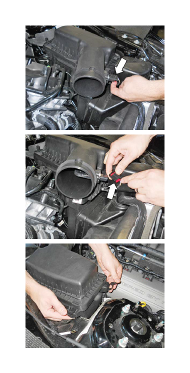
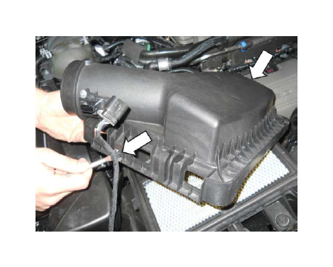
20. Remove the filter from the airbox. Remove the mounting bolt at the side of the airbox (10 mm socket). Pull up and remove the lower airbox from the vehicle.
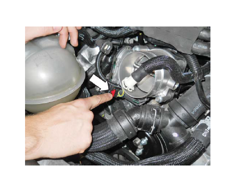
21. Disconnect the brake aspirator.
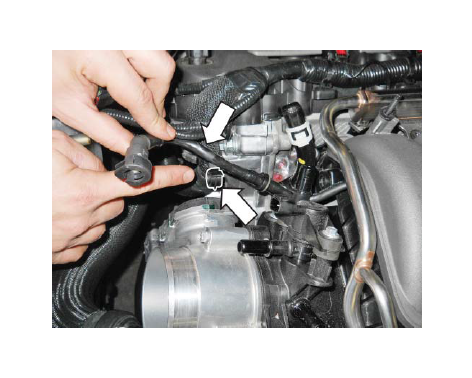
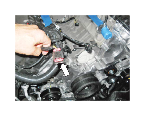
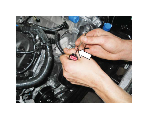
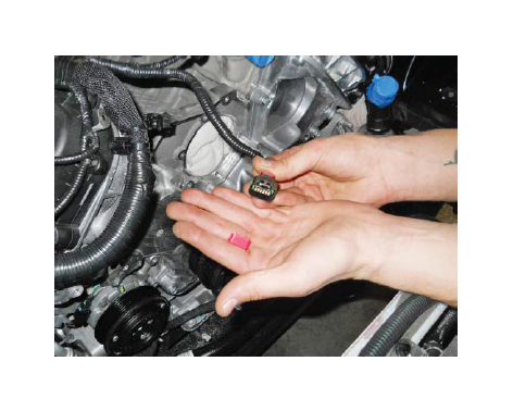
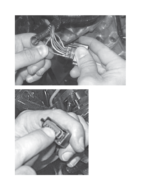
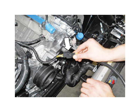
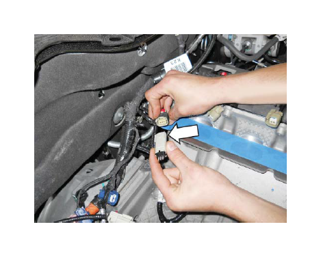
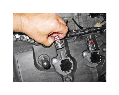
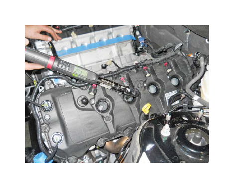
22. Disconnect the throttle body electrical connector. Pull the red locking tab back; press the black release tab to disengage the lock.
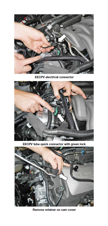
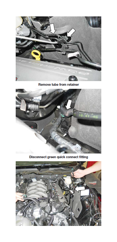
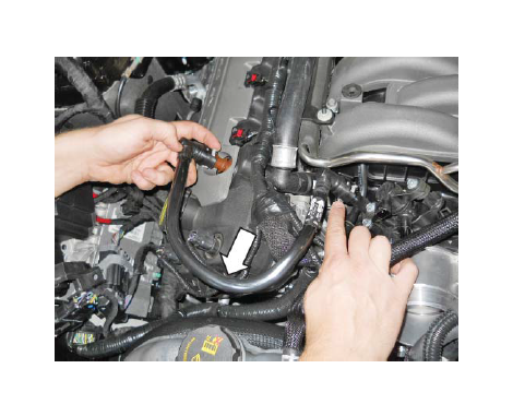
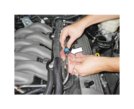
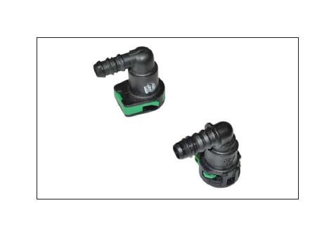
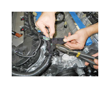
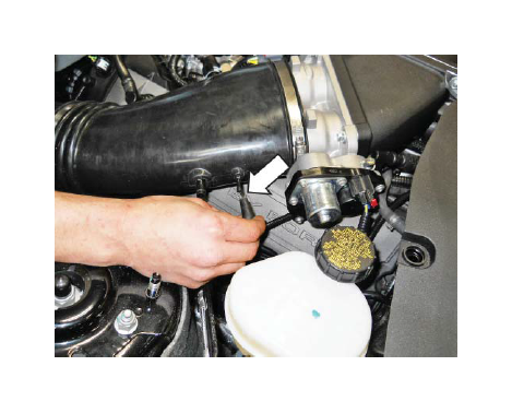
23. Unlock the green connector and disconnect the evaporative emission canister purge valve (EECPV) tube and electrical connector (green). Remove the EECPV tube retainer from the front left hand cam cover. Disconnect the remainder of the tube at the fitting located behind the inner fender (pry from retainer) below the brake booster. Remove from vehicle and set it aside. The quick connect (green locking) connectors must be transferred to the new line in Hardware Kit E.
24. Remove the PCV Purge line from the intake manifold and RH cam cover. This line will not be reused.
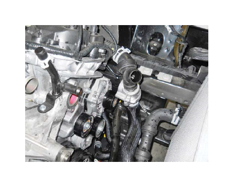
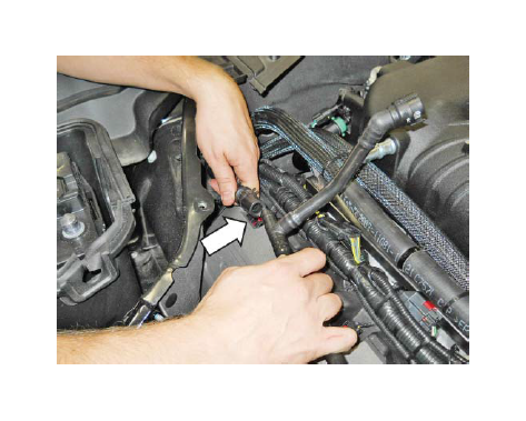
25. Disconnect the fuel supply hose from the fuel rail.
NOTE: Use a rag to catch any excess fuel during disconnection. Use a cap, tape or other suitable method to block the rail opening from contaminants.
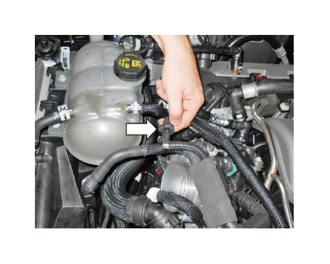
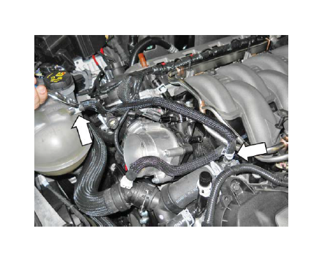
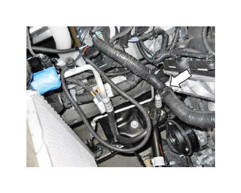
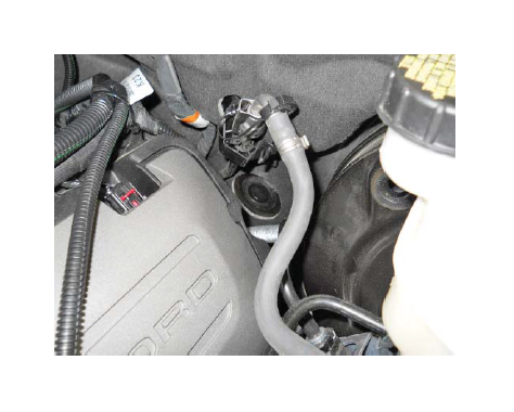
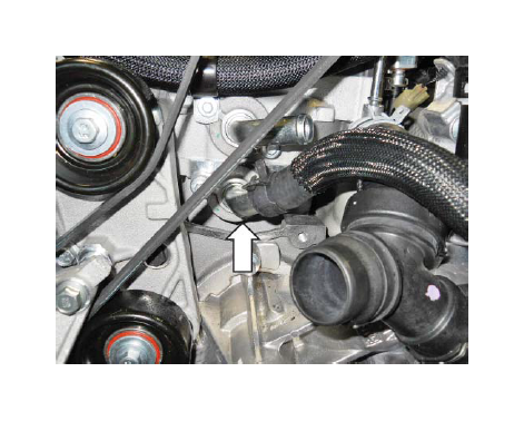
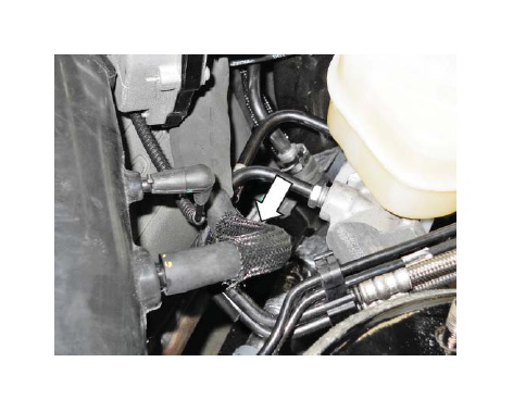
26. Disconnect the brake booster vacuum hose from the intake manifold. This port is located directly behind the throttle body.
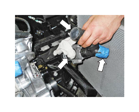
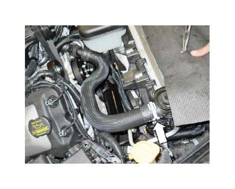
27. Move the LH heater hose aside from the support bracket on top of the LH cylinder head.
28. Remove the two (2) nuts that secure the brake boost vacuum hose and heater hose support bracket to the LH cylinder head.
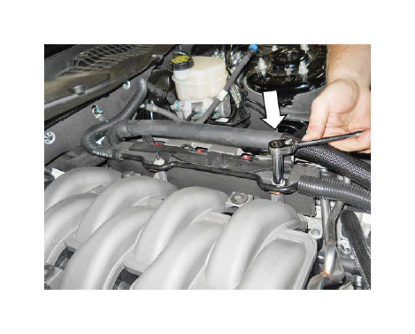
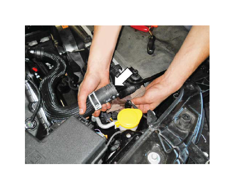
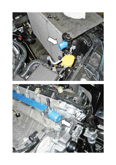
29. Disconnect the brake boost vacuum hose from the port at the firewall.
30. Remove the brake boost vacuum hose/line from the vehicle and set it aside. This line will be modified.
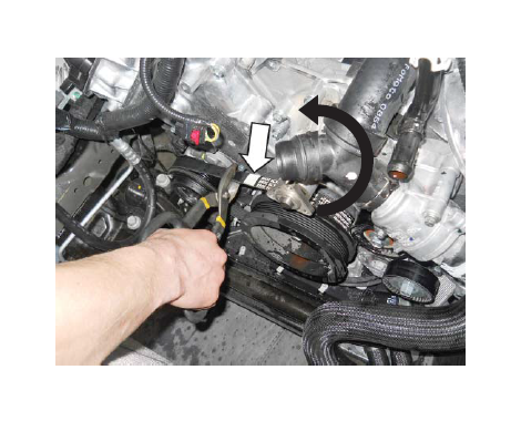
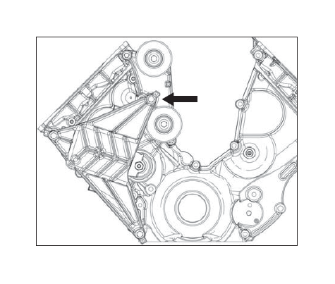
31. Remove the LH heater hose support bracket and fuel rail cover from the LH side of the cylinder head.
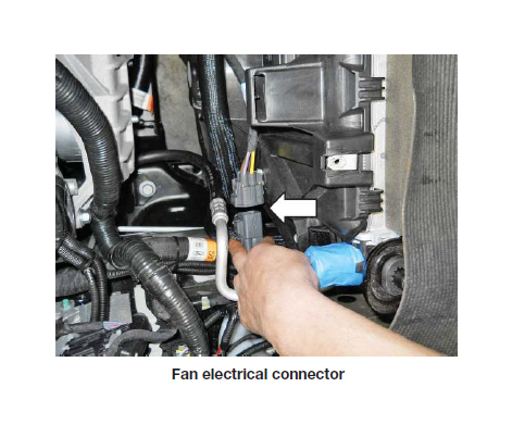
32. Remove the two (2) nuts and support bracket that retained the RH heater hose above the RH fuel rail. This hardware will not be reused. Remove the support bracket and fuel rail cover from the RH cylinder head.
33. Disconnect the heater feed and return hoses located at the front of both the LH and RH cylinder head intake flanges. Disconnect and remove the hoses from the ports on the RH firewall.
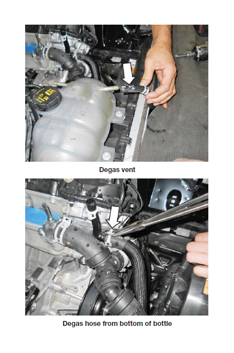
34. Disconnect the clamps on the hose ends and remove the 3/8" engine coolant degas hose from both the engine and the degas bottle.
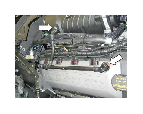
35. Remove the four (4) fuel rail bolts. These bolts will be reused.
NOTE: It is not necessary to remove the fuel rail from the intake manifold assembly.
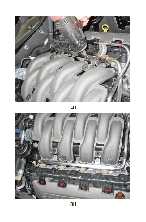
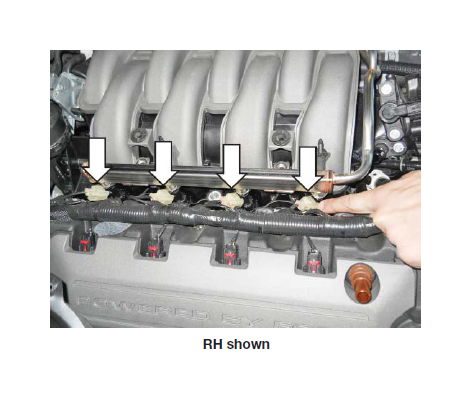
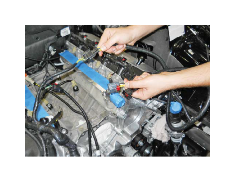
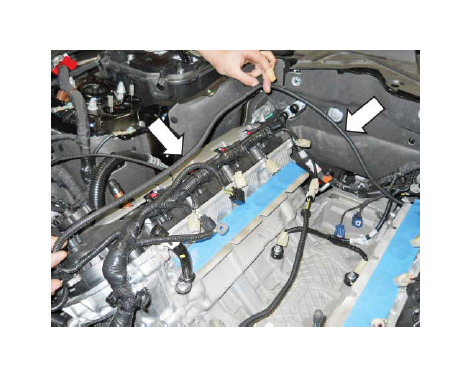
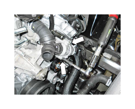
36. Disconnect the eight (8) fuel injector electrical connectors (four [4] on each side).
37. Remove the line from retainer near the front of the RH cylinder head.
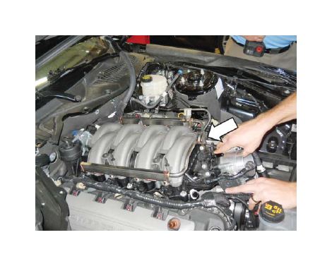
38. Remove the six (6) intake manifold mounting bolts.
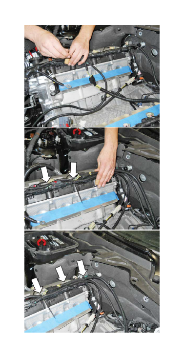
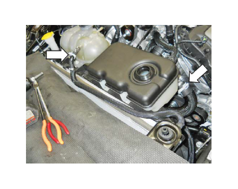
39. Lift the intake manifold and fuel rail assembly straight up and pull it forward to access the harness connectors at the rear. Disconnect the CMCV harness connector. Cut the retaining clip to remove the harness. Use care – Do not cut the harness. Disconnect the four (4) harness connectors. Release/remove the two (2) pushpins.
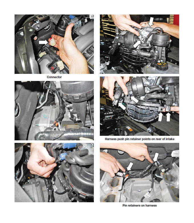
40. Remove the intake manifold and fuel rail assembly from the vehicle. This hardware will not be reused.
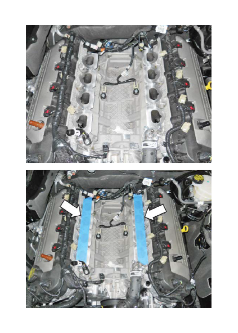
41. Clean the intake mounting surfaces and apply tape over the open intake ports to prevent engine contamination.
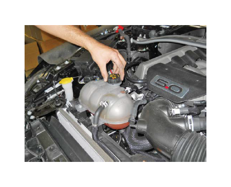
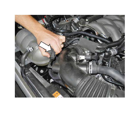
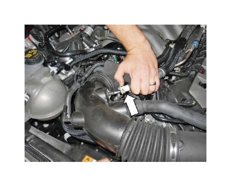
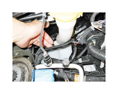
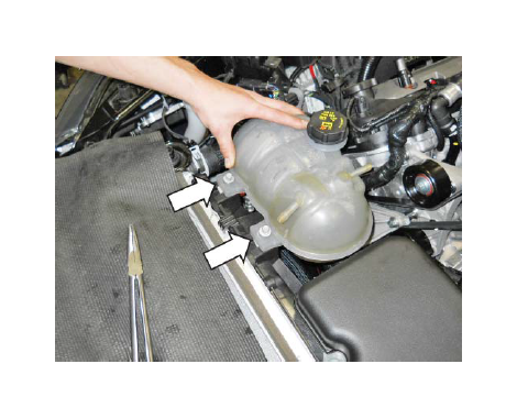
42. Disconnect the vent hose from the engine coolant degas bottle and at the water pump inlet.
43. Remove the two (2) mounting bolts (10 mm socket) and remove the engine coolant degas bottle.
44. Disconnect the clamp on the end of the upper radiator hose at the radiator. Use a rag to catch excess coolant. On the thermostat housing end of the hose, push the clip down on the connector and remove the upper radiator hose from the vehicle.
CAUTION: Some coolant will still be inside the hose. Use a rag to catch coolant when removing the hose.
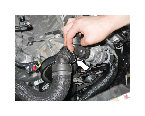
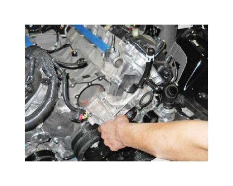
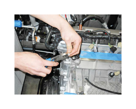
45. Loosen the water pump bolts.
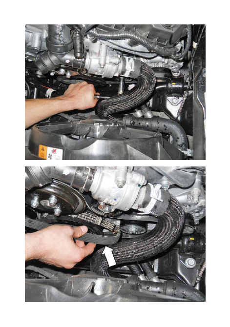
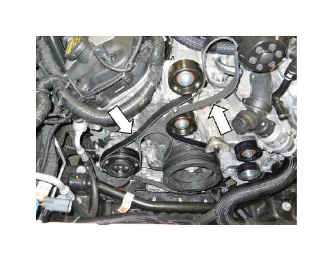
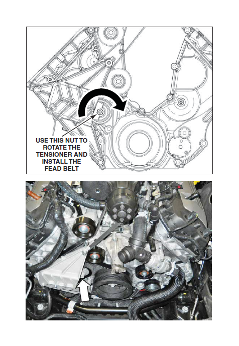
46. Remove the Front End Accessory Drive (FEAD) belt. Rotate the FEAD Tensioner counter-clockwise to release the belt tension and remove the belt. Set the belt aside as it will be reused.
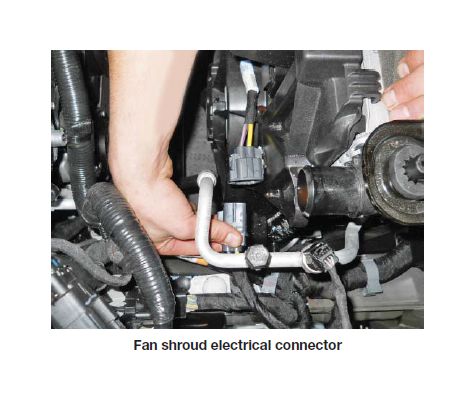
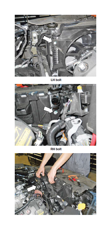
47. Disconnect the electric fan harness connector on the cooling module. Remove the two (2) bolts (10 mm socket) securing the shroud to the cooling module, then remove the electric fan and shroud assembly from the vehicle.
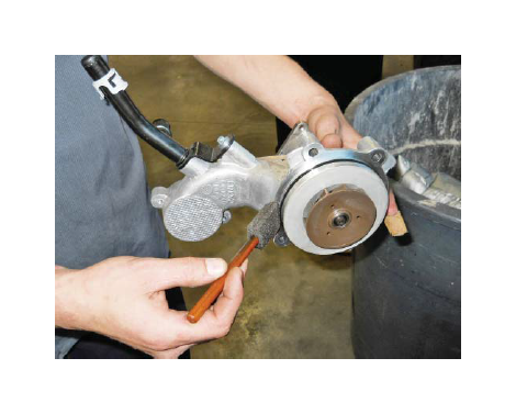
48. Remove the three (3) bolts securing the water pump pulley to the engine and remove the water pump pulley.
49. Cut and remove the A/C compressor belt. Discard belt.
NOTE: Make sure to remove coolant to keep components clean as you continue procedures.
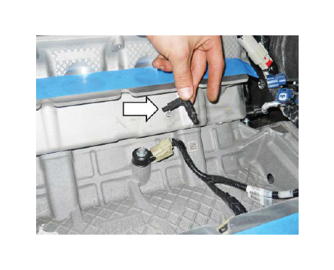
50. Unclip the engine electrical harness retention clips that retain the engine harness to the top corners of the RH (passenger side) front cover.
51. Loosen the clamp and disconnect the coolant hose, at the outlet neck.
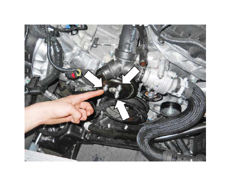
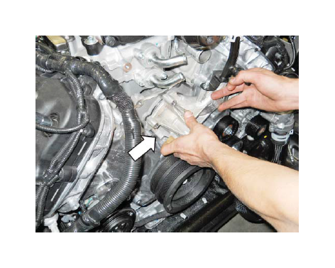
52. Remove the two (2) bolts from the thermostat housing (8 mm socket).
53. Remove the thermostat housing assembly and set it aside.
54. Remove the four (4) water pump mounting bolts (10 mm socket) and remove the water pump. Set both aside for re-use.

55. Place a clean towel in the water pump inlet cavity.
56. Cap or tape off the PCV port, heater feed tube and the heater core ports on the firewall.
57. Tape off the radiator hose port and inlet port.
58. Tape off and block the thermostat housing ports. Use care to prevent coolant from leaking from the housing and hose.
SECTION B – MODIFICATIONS
The following section will guide you through the required modifications of existing components and build up of the assemblies used to complete the installation. With the exception of the wiring modifications and intercooler pump bracket mounting, all of this work can be performed away from the vehicle.
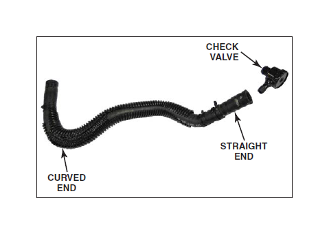
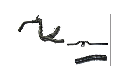
BRAKE BOOSTER VACUUM AND ASPIRATOR HOSE ASSEMBLY MODIFICATION
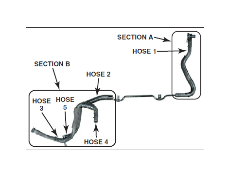
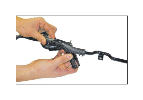
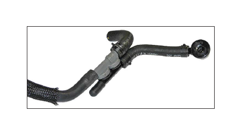
1. Retrieve the brake vacuum hose and aspirator assembly and place it on a work bench.
2. Disassemble the vacuum hose assembly and lay it out on the bench as shown in the following steps.
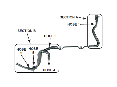
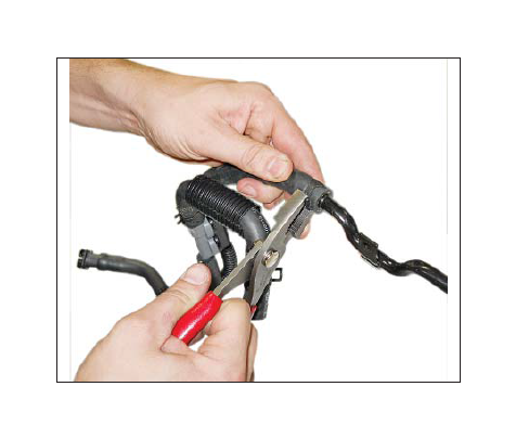
3. Release the clamp and remove Section A, hose 1, from the brake booster hose and aspirator assembly.
4. Release the clamp and remove the check valve from the straight end of hose 1.
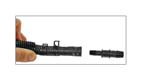
5. Connect the 1/2-to-3/8 Hose-Reducer, Plastic Fitting (1315-3XWD9) found in Hardware Kit D (1315-TVSHKD) into the straight end of hose 1. Secure it with the clamp.
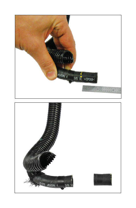
6. Turn hose 1 to the other end. Cut 1" off the curved end of hose 1. Remove convolute as necessary.
7. Return to Section B of the hose/tube assembly. Carefully remove the foam sleeve from the brake aspirator.
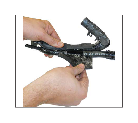
8. Remove the convolute.
9. Release the clamp and separate Section B, hose 2, from the steel tube.
10. Remove the convolute from the curved nylon tube (hose 5).
11. Cut and remove the curved nylon tube from the brake aspirator.
12. Install the Cap Plug (CS2575) found in Hardware Kit D (1315-TVSHKD) on the now open port of the brake aspirator.
13. On hose 4, remove the convolute off of the curved end.
14. Loosen the clamp and rotate the curved hose (hose 4) end 180 degrees. Reinstall the clamp.
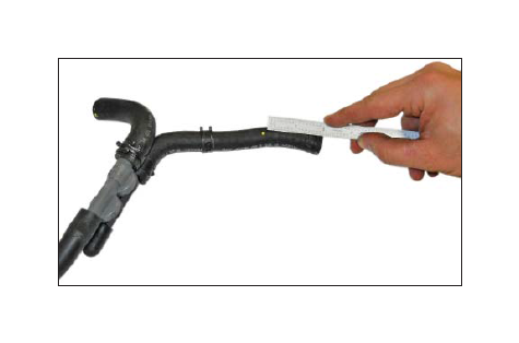
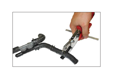
15. On the hose just rotated, mark a line 2" from the bend coming from the aspirator as shown, and cut the hose.
16. Remove the dual clamp from the severed hose. Cut the clamp in half to become a single clamp. Trim the excess metal. Transfer the single clamp to the remaining hose end.
17. On hose 2, mark and cut 2" from the end of the hose.
18. Insert the brake booster check valve on the end of hose 2 and secure it with the clamp.
19. On hose 3, trim 3/4" past the radius on the bend shown. This hose will connect to the clean air tube.
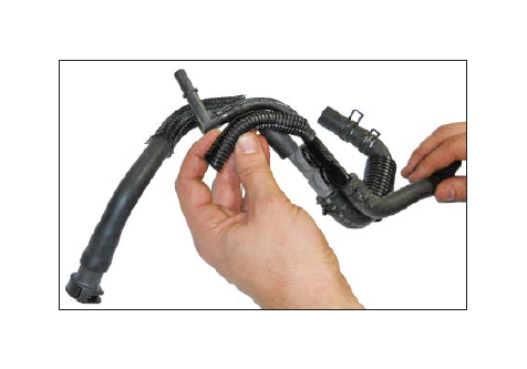
20. Re-wrap the foam sleeve on the modified brake booster hose and aspirator assembly as shown.
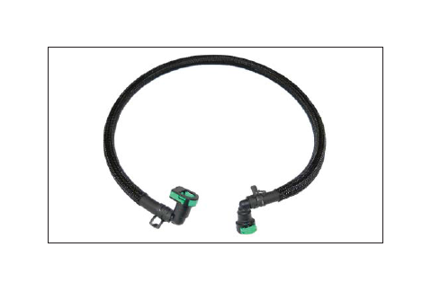
EVAPORATIVE EMISSIONS CANISTER PURGE LINE
1. Remove the convolute and carefully cut the quick connect fittings from both ends of the old EECPV line.
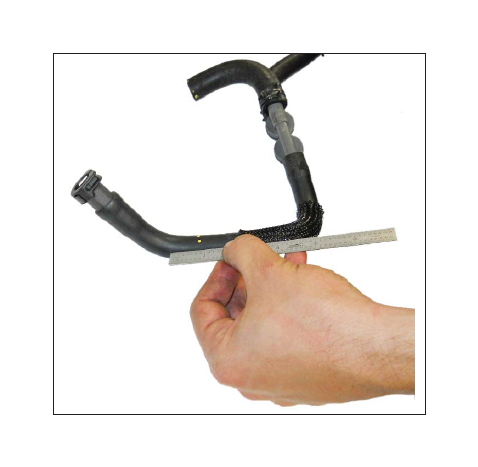
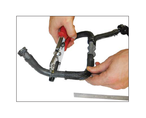
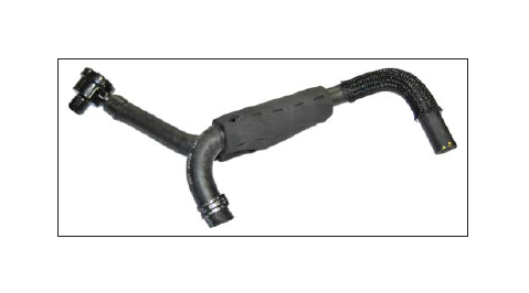
2. Install the Protective Hose Sleeve (1150-18K579SLV) found in Hardware Kit D (1315-TVSHKD) over the 36" length of 3/8" Rubber Hose (1315-9G271).
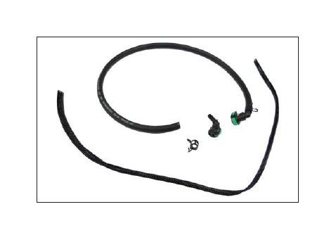
3. Install one (1) Clamp (7329K11) found in Hardware Kit D (1315-TVSHKD) onto each end of the new line. Install the quick connect fittings on the ends of the new line using the orientation shown. Secure the fittings with the clamps.
K-BRACE MODIFICATION
1. As described previously, mark the K-brace where it meets the windshield wiper close-out panel.
2. Use a suitable tool to cut the K-brace in the area marked.
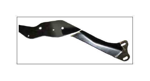
3. Use a suitable tool to file the sharp end where the brace was cut.
4. Paint the cut area with suitable material to prevent corrosion.
ELECTRIC FAN SHROUD MODIFICATION
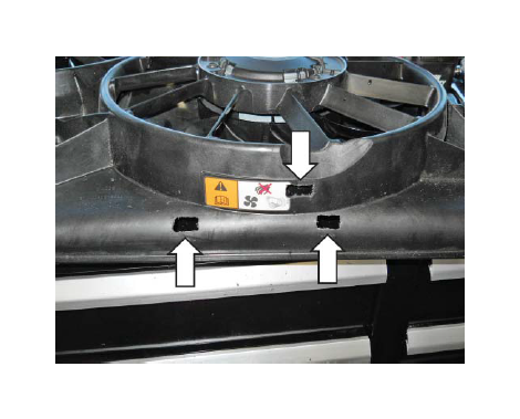
1. Place the IC degas bottle template (1315-DGSTMPL) on the top of the fan shroud and align it with the shroud features. Use a spring-loaded punch or other suitable tool to mark the fan shroud for modification. Remove the template.
2. Use a dremel or other suitable tool to remove material in the three (3) rectangular areas marked as well as the two (2) holes.
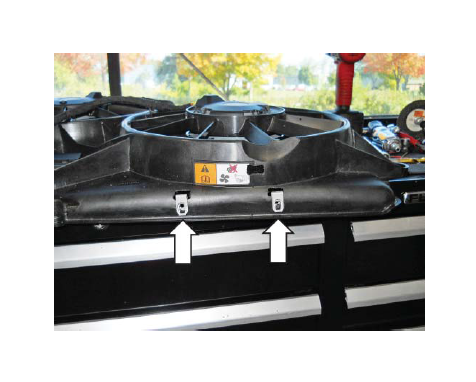
3. Install two (2) J-Clips (N623332-M6) found in Hardware Kit H (1315-TVSHKH) in the two (2) areas on the edge of the shroud.
4. Insert the Clip (20860) found in Hardware Kit H (1315-TVSHKH) onto the tab on the bottom of the Intercooler Degas Bottle (1315-8D080).
5. Position the intercooler degas bottle to the fan shroud and check the fit, but do not install. Remove additional material as required so the bottle fits properly.
FRONT COVER MODIFICATION
WARNING: Wear safe eye protection when grinding to prevent serious personal injury.
1. If not already done so, clean the engine surfaces with brake clean and dry with shop air.
2. Block off the grinding area to prevent debris and metal shavings from spreading through the engine compartment.
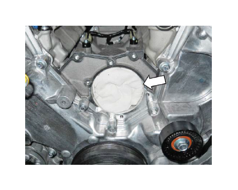
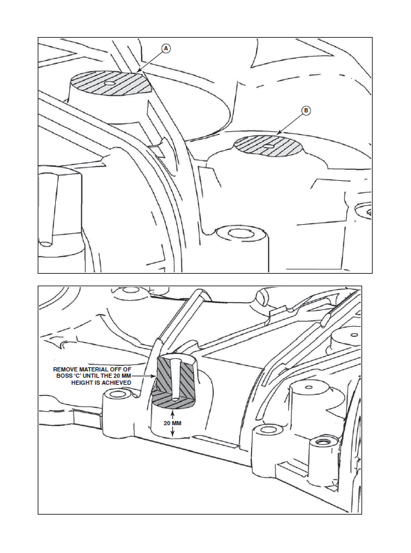
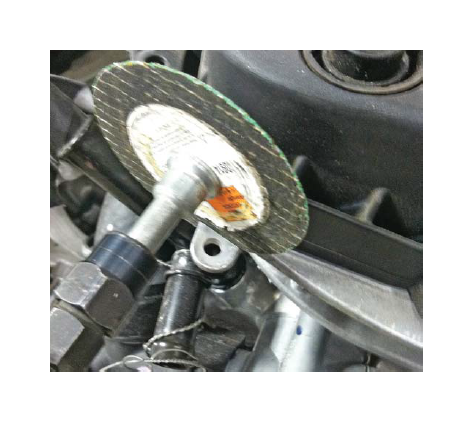
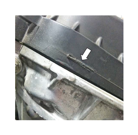
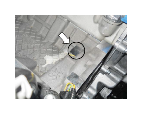
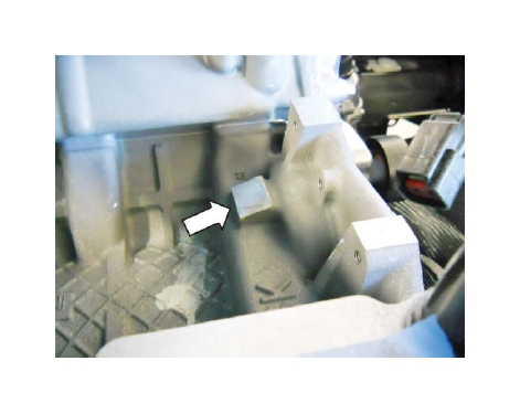
3. Using a grinder or cut-off wheel, modify the front cover in the areas shown. The two (2) bosses located at A and B need to be reduced in height such that they are flush, or lower than the height of the nearby rib structure. The boss located at C needs to be reduced in height and cut in half.
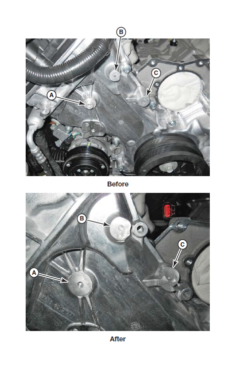
Surfaces A and B, must be lower than or equal to the adjacent rib height. Cut in half and remove material off of boss C until flush.
Refer to the following closeup example views for detail.
Crosshatched surfaces A and B must be lower than or equal to this rib height.
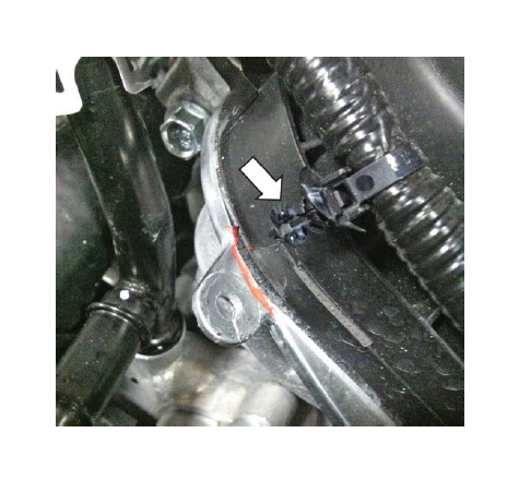
4. Remove the wiring retention clip from the feature on the front cover and set aside.
5. Using a suitable cutting tool, remove the mounting tab. Follow the edge of the part. Use caution as to not contact the cam covers.
6. Deburr any rough edges on the cover and remove the retention harness from the wire harness.
INTAKE VALLEY MODIFICATION
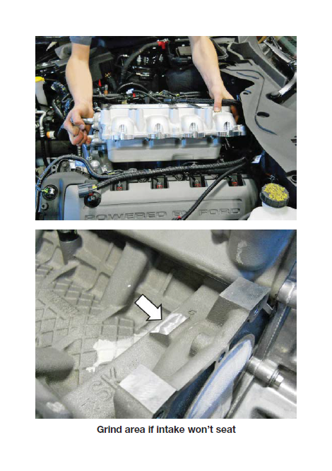
1. Mark the boss in the intake valley behind the water pump mounting location as shown.
2. Use a grinder or suitable tool to grind the boss down across the entire length. Make sure to take off material uniformly along the angle. If high spots are left, the intake manifold will not seat properly on the engine.
3. Vacuum out metal shavings.
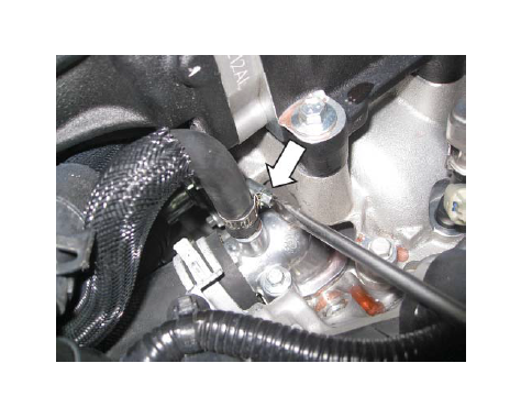
TPS/ETC WIRING
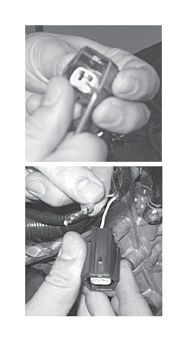
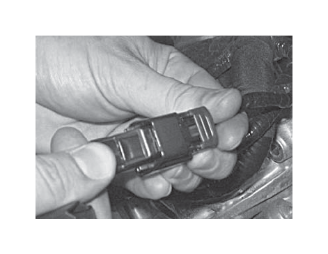
1. Locate the Throttle Position Sensor (TPS) (6-wire) connector and harness at the front of the passenger side cylinder head. Using a proper de-pinning tool, pop out the locking tab and remove the connector from the harness.
2. Depress the locking tab and separate the “empty” female 1 x 6 connector from the new TPS/ETC Extension Harness (131114A595). It will be used in the next step.
3. Populate the new connector such that the yellow with violet wire is in position 1, the blue with green wire is in position 2, the brown wire is in position 3, the blue with orange wire is in position 4, the yellow wire is in position 5 and the green with violet wire is in position 6. Install the red plastic lock into the connector to secure the wires in place.
4. Connect the TPS/ETC Extension Harness (131114A595) from Hardware Kit E (1315-TVSHKE) to the newly installed connector. The wire colors on each side of the connector pair should align. Route the harness along the main wiring harness to the rear of the driver side cam cover. Use tape or zip ties to secure the extension harness to the main harness.
EVAPORATIVE EMISSIONS CANISTER PURGE VALVE WIRING
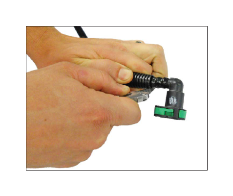
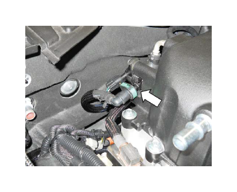
1. Locate the Evaporative Emissions Canister Purge Valve electrical connector (2-wire) at the front of the passenger side cylinder head. Use a proper de-pinning tool to remove the connector from the harness.
2. Depress the locking tab and separate the “empty” female 1 x 2 connector from the Evaporative Emissions Canister Purge Valve Extension Harness (13119G866). This connector replaces the connector removed in the previous step. Carefully pull the white locking tab forward to allow wires to be installed into the connector. Populate the new connector such that the white with brown wire is in position 1 and the green wire is in position 2. Depress the white locking tab to secure the wires.
3. Connect the Evaporative Emissions Canister Purge Valve Extension Harness (13119G866) to the newly installed connector. The wire colors on each side of the connector pair should align. Route the harness along the main wiring harness to the rear of the passenger side cam cover. Use tape or zip ties to secure the extension harness to the main harness.
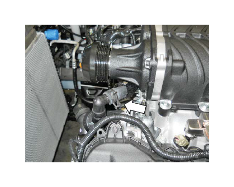
AIR CHARGE TEMPERATURE (ACT) WIRING
1. Locate the IMRC sensor connector (light grey) at the rear of the passenger side cylinder head.
2. Connect the IMRC sensor connector into the ACT Wiring Harness (1315-12A690), found in Hardware Kit E (1315-TVSHKE).
3. Route the extension wiring harness to the RH side cylinder head.
4. Install the Connector Block (1315-14A464), found in Hardware Kit E (1315-TVSHKE), into the IMRC 3-pin sensor connector (dark grey) located at the rear of the driver side cylinder head.
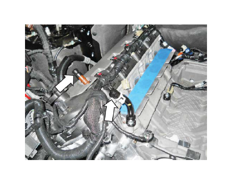
TPS/ETC AND EECPV HARNESS ROUTING
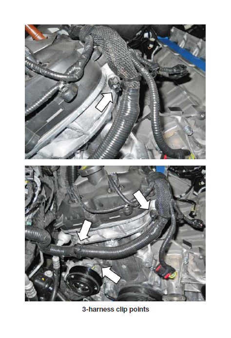
1. Remove the wiring retainer and clip on the engine harness.
2. Route both extension harnesses along the engine harness. Secure them in place with zip ties.
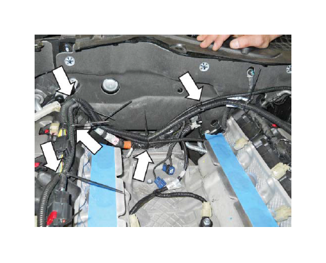
3. When complete, the secured harnesses will look similar to this. Trim the excess length from the zip ties.
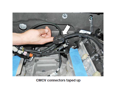
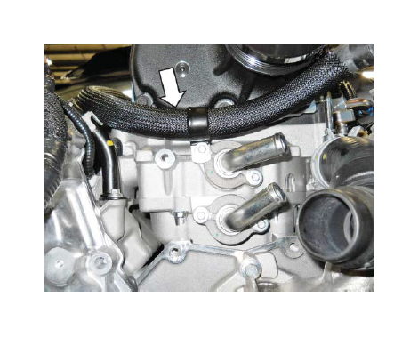
4. Wrap electrical tape around the two (2) blue CMCV connectors at the rear of the cylinder head as shown.
ENGINE HARNESS GROUND WIRE
1. Pry up the engine harness retainers at the RH front and side of the engine.
2. Peel back the insulation at the base of the ground wire that was attached to the stud on the front cover. Trim back part of the insulation until the ground wire is exposed.
3. Separate the ground wire further back into the harness. This will create slack necessary for relocating the ground.
4. Rewrap the ground wire with electrical tape.
5. Use snips to cut off the bent metal tab on the end of the ground tab.
6. Using a step bit, drill the hole on the tab to enlarge the opening. The hole must be larger to accommodate a larger bolt.
TIP: Hold the tab with pliers when drilling to keep the tab stationary.
INTERCOOLER PUMP WIRING
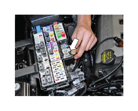
1. Lift up the fuse box by releasing the two (2) retaining tabs and locate the hole underneath the fuse box near the PCM. The intercooler pump relay will be attached at this location.
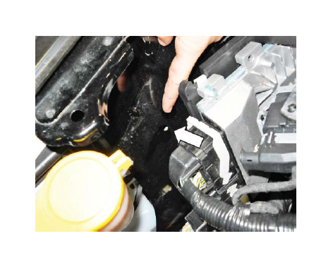
2. Install the relay and fuse from the Intercooler Pump Wiring Harness (1315-8W501) through the hole and secure it with one (1) M6 x 14 Bolt (N605771) and one (1) M6 Nut (W520412). These parts can be found in Hardware Kit E (1315-TVSHKE).
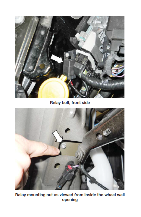
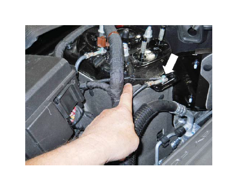
Relay mounting nut as viewed from inside the wheel well opening
3. Lay the intercooler pump wire harness along the
engine harness, in back of the cylinder head to the driver side inboard cylinder head. Disconnect the radio capacitor and plug the intercooler pump harness in line with this connector.
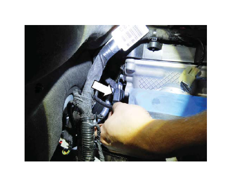
4. Route the intercooler pump wire harness in back of the cylinder head along the RH engine harness to the area near the fuse box.
5. Install the intercooler pump harness red power wire to the first post in the fuse box. Tighten the nut to 10 Nm.
6. Install the ground wire with the existing ground wire near the RH strut tower and retighten the bolt to 10 Nm. Coil up the extra wire slack.
7. Route and tuck the intercooler pump harness under the engine harness and down the RH coil cover towards the fuse box as shown. Secure it in place with zip ties.
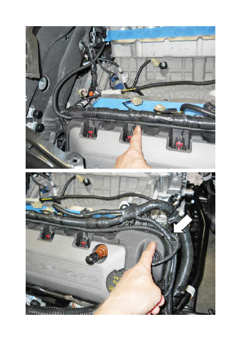
8. Retain the engine harness to the front cover using the zip tie with fur tree (156-00329) found in Hardware Kit E (1315-TVSHKE).
9. Route the intercooler pump wire harness over the top and in front of the wiper washer bottle. Secure it in place with zip ties as necessary.
10. Zip tie the excess harness out of the way and secure it to a safe location.
KNOCK SENSOR ORIENTATION ADJUSTMENT
The knock sensors must be reoriented and the harnesses rewrapped to accommodate the new fuel charging assembly. It will be necessary to split the two (2) sensor wires further up the harness in order to gain the necessary slack for proper sensor positioning towards the side of the engine valley.
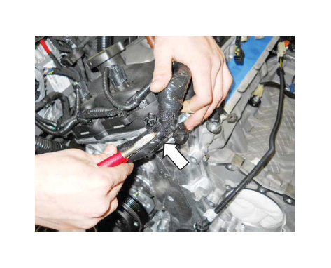
1. Remove the 90-degree plastic wiring retainer clipped to the connector and taped to the wiring convolute.
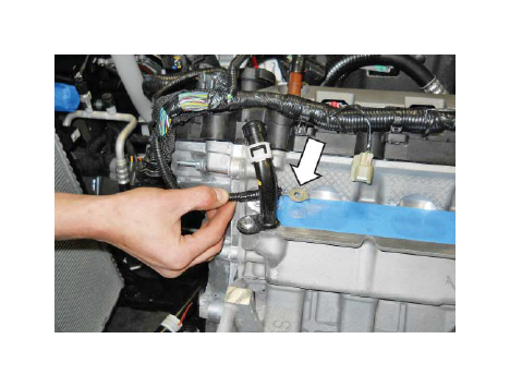
2. Loosen the two (2) bolts which retain the knock sensors to the engine block (10 mm socket). If necessary, one (1) of the bolts and sensors can be removed for this modification process.
3. Peel back the tape from the connectors and remove the convolute approximately 1-1/2" past where they meet at the harness.
4. Temporarily fit the sensors as follows to determine where to rewrap the wires. Install and rotate the RH and LH knock sensors as far as possible to the outside of the valley of the block. Check that the sensors lay low on the engine valley so they will not interfere with the fuel charging assembly once it is installed.
5. Reinstall the convolute and rewrap the wires with electrical tape as required.
6. Install the knock sensors in position. Install the bolts and torque them to 20-30 Nm.
CHANGING THE FACTORY SPARK PLUGS
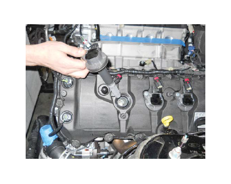
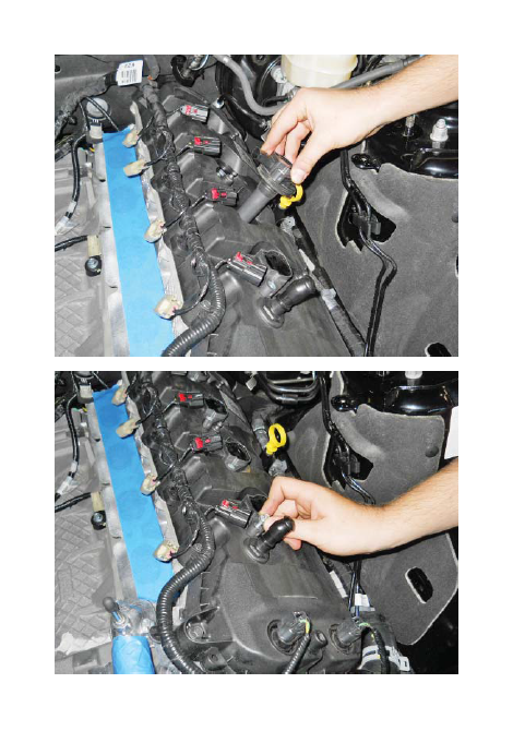
1. Remove the coil covers by gently pulling up on them. Remove the oil cap prior to removing the RH coil cover.
2. Disconnect the electrical connectors for each ignition coil (eight [8] places).
3. Remove the eight (8) fasteners holding the coil on plug assemblies in place (8 mm socket). Save the fasteners for re-use.
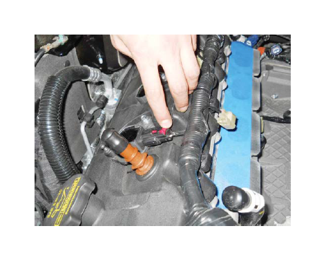
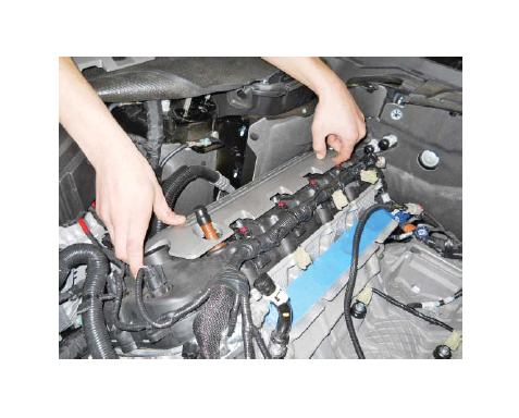
4. Remove the coil on plug assemblies and label them so they can be reinstalled in their original position. A slight twisting motion will break the seal and ease removal.
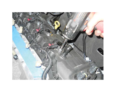
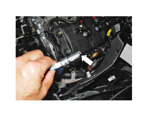
5. Use a 5/8" spark plug socket and 6" extension to remove the eight (8) factory spark plugs and set aside. These will not be re-used.
NOTE: Use a universal swivel socket at the rear RH plug.
6. Unpack the eight (8) provided Spark Plugs (BL3E-
12405) which are pre-gapped to 0.9 mm. Check to ensure the gap is intact and none are damaged.
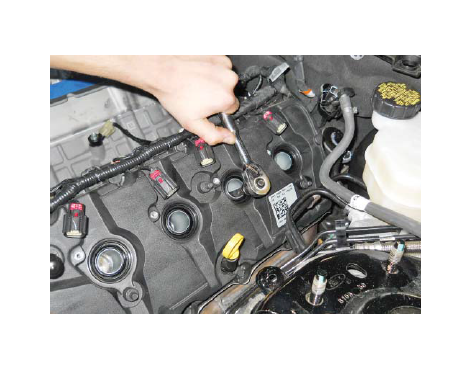
7. Install the new spark plugs using a 5/8" spark plug socket and 6" extension. Torque to 14 Nm.
NOTE: Use a universal swivel socket for the RH rear plug.
8. Apply a small amount of dielectric grease to the inside of the coil on plug boots before attaching to the spark plugs. Install the ignition coil on plugs in their original position. Install the coil on plug bolts and torque to 6 Nm.
9. Connect the electrical connectors for each ignition coil eight (8) places.
10. Re-install the coil on plug covers. Reinstall the oil cap after the RH cover is installed.
SECTION C – SUBASSEMBLY
INTERCOOLER LOW TEMPERATURE RADIATOR (LTR)
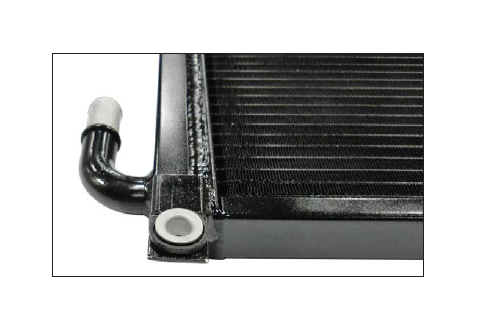
1. Insert one (1) Rubber Grommet (R07060107) found in Hardware Kit H (1315-TVSHKH) into each lower tab on the Low Temperature Radiator (LTR) Assembly (1315-8K229).
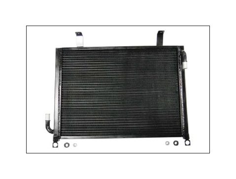
2. Push one (1) Sleeve (R07060108) found in Hardware Kit H (1315-TVSHKH) into each of the rubber grommets.
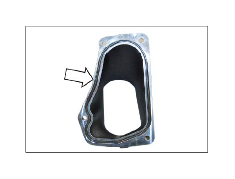
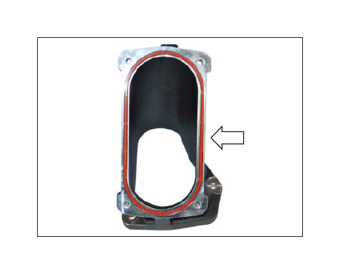
INTAKE MANIFOLD BUILDUP
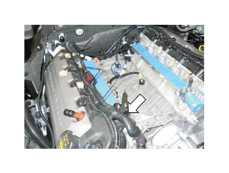
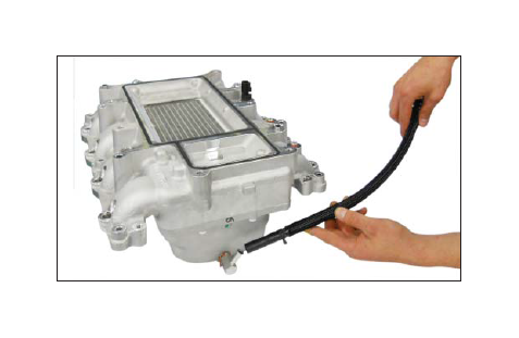
1. Remove the PCV Purge Hose (13116K817) from the packaging. Release the clamp and separate the rubber section of hose as shown.
2. Attach the rubber hose section from the PCV Purge Hose to the bubbler fitting (3/8" barb) on the bottom rear of the intake manifold (1315-9H487) and secure it with the supplied clamp.
SUPERCHARGER BUILDUP
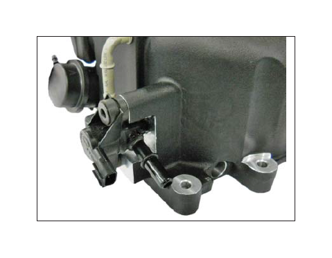
1. Remove the two (2) bolts and the Evaporative Emission Canister Purge Valve from the stock intake manifold (8 mm socket). Discard the bolts.
2. Install the valve into the rear of the supercharger (1315-6F066) using two (2) M6 x 1.0 x 35.5mm Bolts (N808429) found in Hardware Kit B (1315-TVSHKB). Torque bolts to 8-12 Nm.
3. Connect the Supercharger Boost Bypass Actuator Hose (1315-9E498) found in Hardware Kit D (1315-TVSHKD) to the top port on the actuator and route to the small port on the supercharger.
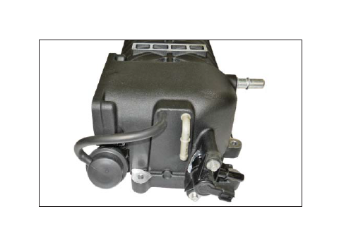
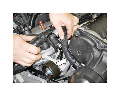
4. Connect the brake boost hose to the 90-degree tube at the rear of the supercharger and secure it with the clamp. This is “hose 1” created from the brake boost vacuum and aspirator assembly modification process.
5. Connect the Supercharger Bypass Reference Vacuum Line (7R3V-9E498) to the bottom fitting on the supercharger bypass actuator.
NOTE: This line will later be routed underneath the heater hose and fuel line.
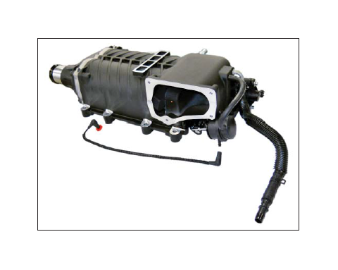
6. Install the supercharger badge (1315-6F066BDG) onto the top of the supercharger.
FUEL RAIL ASSEMBLY
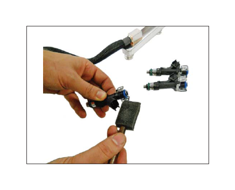
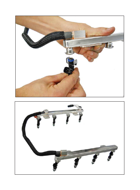
1. Carefully install the eight (8) new Anti-Rotation Fuel Injector Clips (1311-9C995) onto the new Fuel Injectors (13119F593K Fuel Injector Kit).
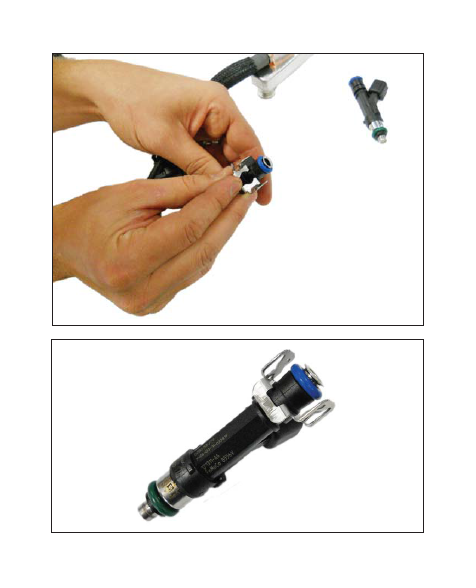
2. Apply assembly lube to the injector O-rings and install the injectors into the new Fuel Rail (1315-19F792).
NOTE: Verify that the anti-rotation clips are properly aligned and fully engaged into the fuel rail injector cups.
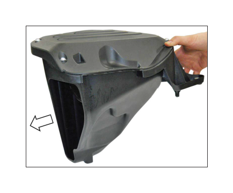
AIRBOX ASSEMBLY
1. Insert the Dirty Air Duct (1315-9F763) and install
it into the Lower Airbox Tray (1315-9A612) as shown.
NOTE: These may be separated if needed to ease installation to the vehicle.
2. Insert the two (2) J-Clips (W520823) from Hardware Kit A (1315-TVSHKA) onto the airbox tray as shown.
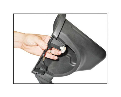
3. Place the MAF Tube Assembly (1315-12B579HC) through the opening of the airbox tray from the inside.
4. Align the holes on the MAF tube assembly with the J-Clips on the airbox tray. Install two (2) Bolts (W500224) (M8 X 25) from Hardware Kit A (1315-TVSHKA) and torque to 10 Nm (10 mm socket).
5. Install the Filter (1315-9601R) onto the MAF tube and secure it with the supplied clamp. Torque clamp to 3-5 Nm.
6. Remove the MAF sensor from the factory airbox lid. Retain the bolts for reuse.
7. Transfer and install the factory MAF sensor into the MAF tube assembly using the original MAF sensor bolts (M4 X 0.7 X 10) and tighten with a T-20 Torx bit. Torque the screws to 1.8–2.2 Nm. Be careful not to over tighten these screws. Wiggle the MAF sensor to ensure that it is properly fastened.
8. Install the Upper Airbox Cover (1315-9643) on the airbox tray. Using a T-30 Torx head bit, install six (6) Bolts (W506976) from Hardware Kit A (1315-TVSHKA).
9. Remove the grommets and sleeves from the factory lower airbox. Install the grommets and sleeves onto the new airbox assembly.
TIP: Remove the center bushing while installing the rubber grommet through the hole in the tab. Re-install the center bushing once the grommet is fully seated.
10. Remove the rubber mounting isolator from the bottom of the factory airbox and install it onto the mount on the bottom of the new airbox in the same orientation.
SECTION D – INSTALLATION
The following section will guide you through the final installation of the kit into the vehicle. If you need to stop during any part of the installation, make sure you cover any open ports in the cylinder heads or intake manifold to prevent foreign material from contaminating your engine.
INDUCTION RESONANCE TUBE DELETE GROMMET
1. Obtain the Induction Resonance Tube Delete Grommet (W651016) from Hardware Kit A (1315-TVSHKA).
2. Install the Induction Resonance Tube Delete Grommet in the hole that was exposed when the resonance tube was removed.
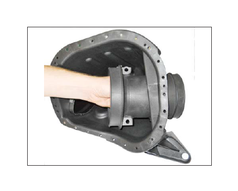
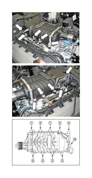
INTAKE MANIFOLD, FUEL RAILS, SUPERCHARGER, SPACER AND THROTTLE BODY
1. Remove the tape from the cylinder heads and clean the cylinder head to intake manifold mating surfaces.
2. Install the Fuel Charging Assembly (1315-9H487) and check to make sure it is seated completely. If not, remove it and grind the modified area in the engine valley again until the manifold seats properly.
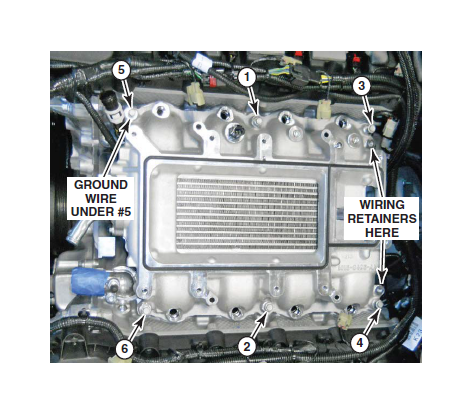
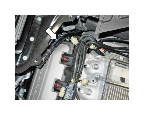
3. Install the engine harness ground wire tab at the RH front of the intake manifold using one (1) of the M6 x 1.0 x 40 mm Bolts (R18020004) found in Hardware Kit B (1315-TVSHKB). Do not tighten the fastener down until the next step. Zip tie the ground wire to the engine harness.
4. Install the other five (5) M6 x 1.0 x 40 mm Bolts (R18020004) found in Hardware Kit B (1315-TVSHKB) in the positions shown. Torque all six (6) bolts to 8-12 Nm following the sequence shown. Reinstall the engine wiring harness retention clips at the rear of the intake manifold.
5. Check that the hose in back of the intake manifold is routed around the electrical harness and towards the RH cam cover.
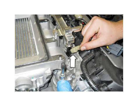
6. Connect the ACT sensor from ACT Harness (1315-12A690) to the intake manifold.
7. Lube the lower fuel injector O-rings with assembly lube. Install the fuel rail and injectors into the intake manifold. Be sure each injector is properly seated into the intake manifold. Install the previously removed fuel rail mounting bolts. Tighten the bolts to 8-12 Nm using the pattern shown.
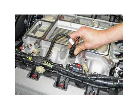
8. Connect the eight (8) fuel injector electrical connectors.
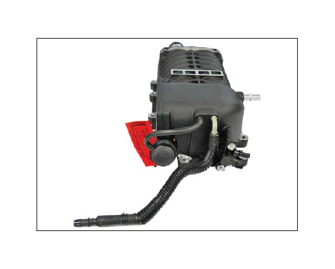
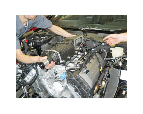
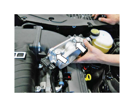
9. Carefully place the Supercharger Assembly (1315-6F066) on top of the intake manifold. Ensure that the supercharger is fully seated on the intake mounting dowels. Remove protective shipping covers.
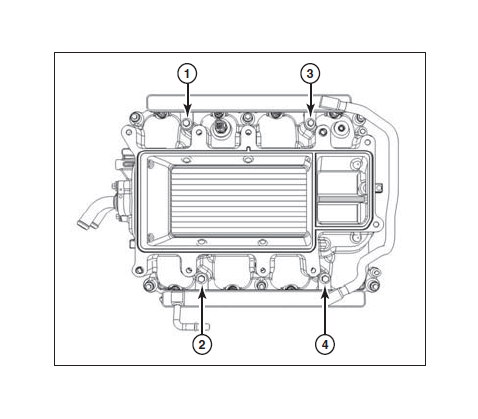
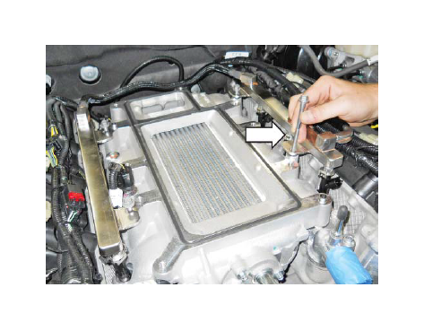
10. Install the ten (10) M8 x 1.25 x 53 Fasteners (N808130) provided found in Hardware Kit B (1315-TVSHKB) into the mounting holes. Torque fasteners to 25 Nm in the sequence shown (10 mm socket).
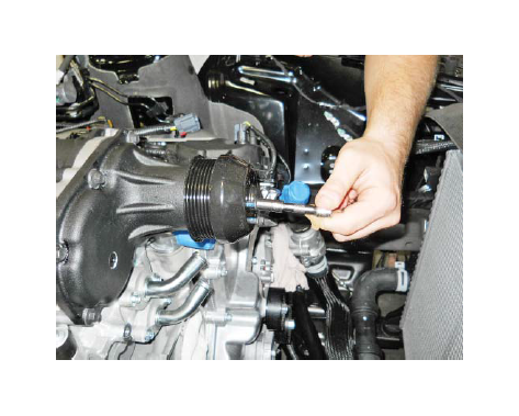
11. Install the 85 mm Supercharger Pulley (1313-6K85) onto the hub of the supercharger using the six (6) M6 x 16 Bolts (W500013) found in Hardware Kit B (1315-TVSHKB). Apply a small amount of blue thread locking compound to each bolt and torque to 8-12 Nm.
HINT: You may need to torque the supercharger pulley bolts once the FEAD belt is installed.
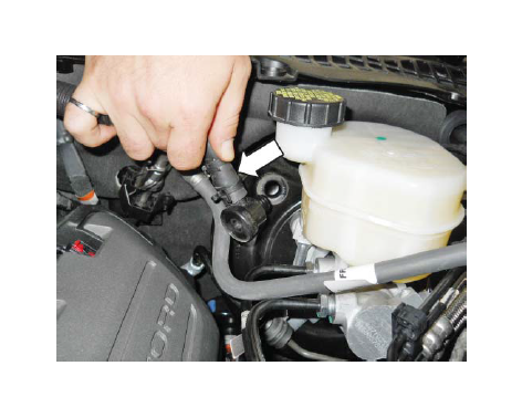
12. Install the brake aspirator hose assembly. Connect the hose (with 1/2" barbed fitting) from the supercharger to the 1/2" brake line and secure it with the attached clamp.
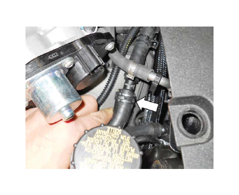
13. Connect the check valve on the brake vacuum and aspirator assembly to the brake booster.
14. Inspect the installation of the brake boost vacuum and aspirator assembly in the vehicle to ensure there are no pinched hoses and the convolute is positioned to prevent hose abrasion from other components.
15. Install the Spacer-To-Supercharger Gasket (1315-9E152) found in Hardware Kit B (1315-TVSHKB) on the Throttle Body Spacer (1315-9P697) as shown.
16. Install the Spacer-To-Throttle Body Gasket (R07060153-13) found in Hardware Kit B (1315-TVSHKB) as shown.
17. Mount the Throttle Body Spacer (1315-9P697) using four (4) M6 x 32.5 Fasteners (R18020009). These parts can be found in Hardware Kit B (1315-TVSHKB). Torque the fasteners to 10 Nm.
18. Connect the fuel supply line to the fuel rail and lock it into position.
19. Install the Throttle Body Assembly (R07060150) on the throttle body spacer. Use four (4) M6 x 32.5 mm Bolts (R18020009) found in Hardware Kit B (1315-TVSHKB) to secure the throttle body assembly to the spacer. Torque bolts to 10 Nm.
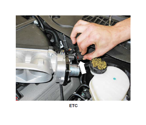
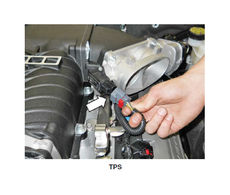
20. Install the ETC and TPS electrical connectors to the throttle body.
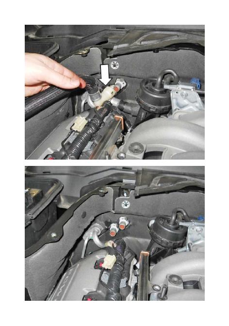
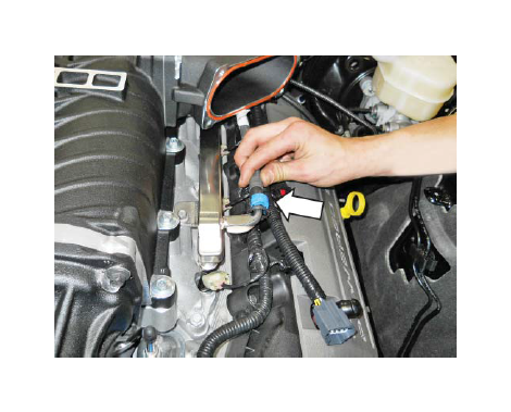
21. Plug the Evaporative Emission Canister Purge Valve Extension Harness (13119G866) electrical connector into the relocated Evaporative Emission Canister Purge Valve on the back of the supercharger.
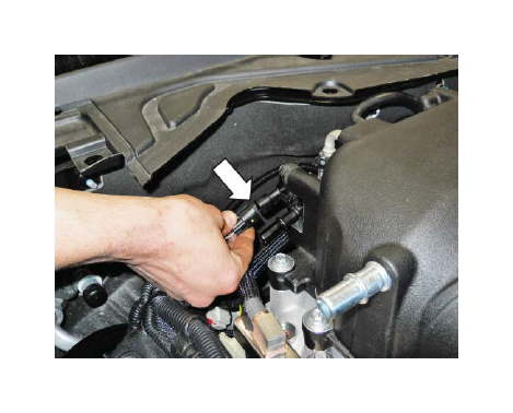
22. Install the Evaporative Emission Canister Purge Valve Line to the body line tube below the brake booster. Slide the green clip to lock the connector. Route the rest of the line behind the cylinder head to the RH rear of the supercharger.
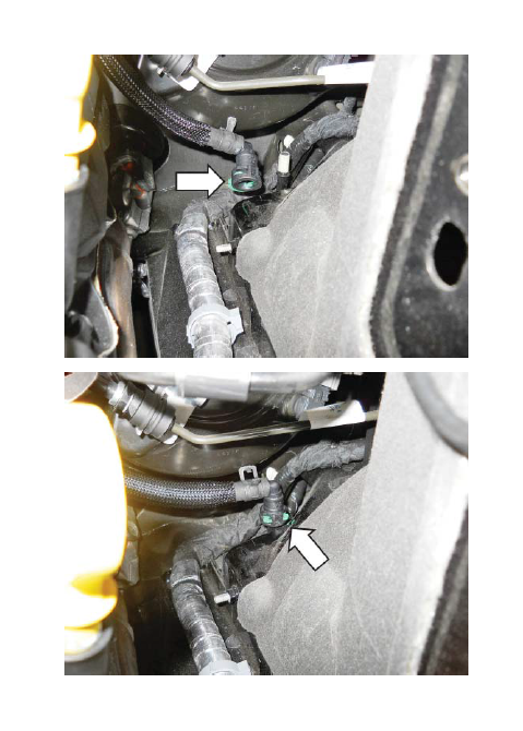
23. Connect the new Evaporative Emission Canister Purge Valve Line (1315-9G271), to the relocated Evaporative Emission Canister Purge Valve on the back of the supercharger. Slide the green clip to lock the connector.
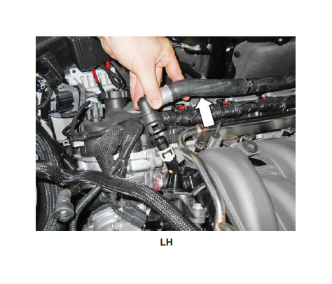
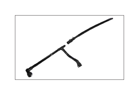
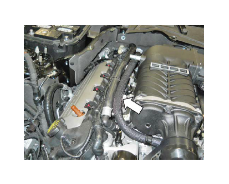
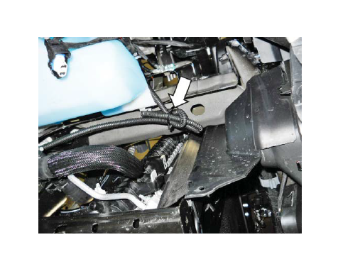
24. Connect the Heater Hose Assembly (1315- 18K579) to the heater tube near the front of the LF cylinder head.
25. Route the line around the front of the engine underneath the snout of the supercharger towards the heater core. Remove the top intercooler tube bolt and install the P-clamp tab using the fastener on the intercooler coolant inlet.
26. Route the hose along the RH fuel rail and down to the heater outlet at the firewall.
27. Install the heater hose connector to the bottom port (heater outlet) at the RH firewall.
28. Install the 424mm length of protective hose sleeve (1311-18K579) found in hardware kit D (1315-TVSHKD) over the RH factory heater hose and secure with tape on either end of the sleeve. Reinstall the RH factory heater hose to the tube at the RH front of the engine.
29. Route the hose along the top of the RH fuel rail and connect it to the top heater core port (inlet) on the RH firewall.
30. Secure the heater inlet hose to the new heater outlet hose assembly with zip ties.
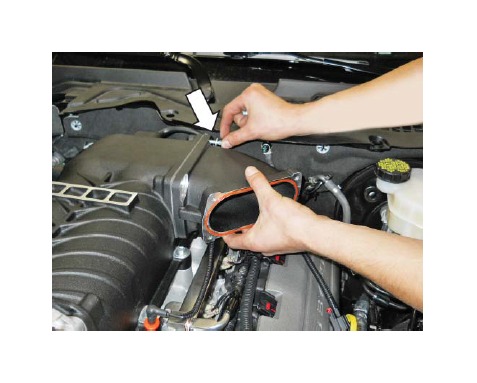
31. Install the end of the PCV Purge Hose (13116K817) from the hose section previously disassembled onto the bottom rear fitting of the intake manifold. Install the clamp.
32. Connect the PCV Purge Line (13116K817) to the PCV Valve on the RH cam cover and the port on the RH side of the supercharger.
FEAD ASSEMBLY
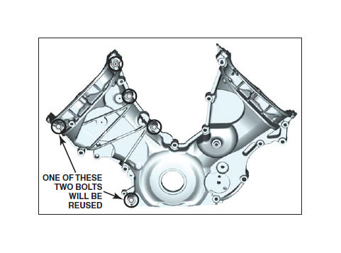
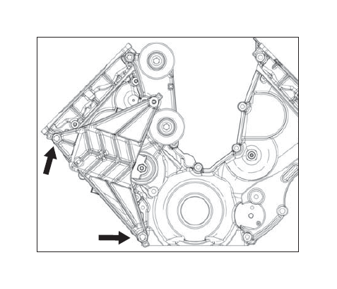
1. Remove the four (4) bolts and one (1) stud from the front cover as shown.
2. Lube the water pump gasket.
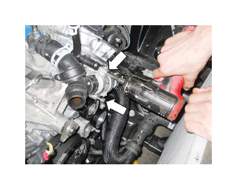
3. Install the water pump on the front cover and install the three (3) bolts only. Leave out the bolt at the 10 o’clock position. Torque the bolts to 25 Nm.
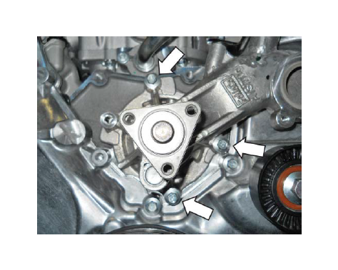
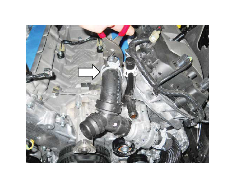
4. Install the thermostat housing and hose assembly and secure it with the clamp.
5. Install the two (2) thermostat housing mounting bolts and torque to 10 Nm.
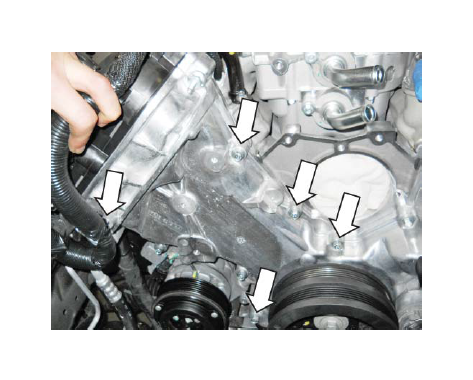
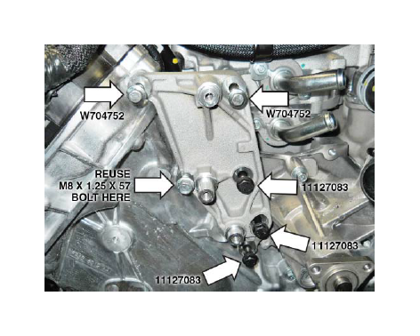
6. Install the Upper FEAD Bracket (1314-8B653U) using one (1) M8x1.25x57 bolt (that was removed in the step 1 of this section), three (3) (black) M8x1.25x60 bolt (11127083) and two (2) M8x1.25x84 Bolts (W704752) from Hardware Kit C (1315-TVSHKC). Torque bolts to 25 Nm.
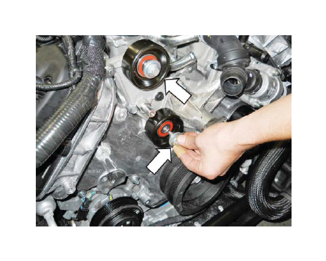
7. Install two (2) Idler Pulleys (953045) onto the machined posts of the Upper FEAD Bracket. Secure the pulleys using two (2) M8 x 1.25 x 28 mm Idler Bolts (R18020060) with washers found in Hardware Kit C (1315-TVHSKC). Torque bolts to 25 Nm (13 mm socket).
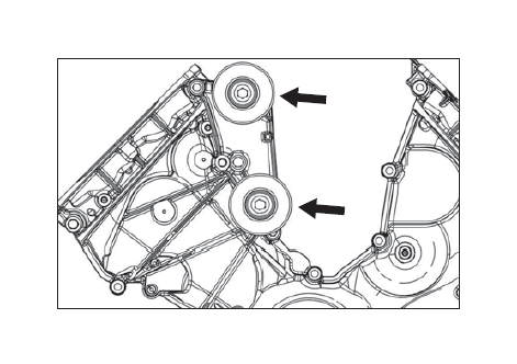
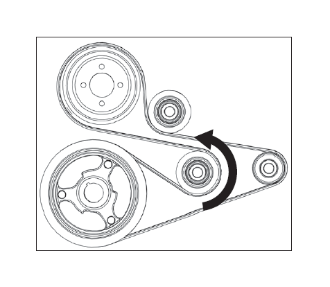
8. Route the FEAD Belt (K060806) as shown. Do not route the belt onto the supercharger pulley.
9. Loosely install the FEAD Tensioner Bracket Assembly (13118B603) onto the front cover using two (2) M8 x 1.25 x 120 mm Bolts (N811329) found in Hardware Kit C (1315-TVSHKC).
NOTE: Install the lowest bolt into the casting prior to positioning in vehicle, in order to clear the sway bar.
10. Install one (1) M8 x 1.25 x 41 mm Bolt (W705128) found in Hardware Kit C (1315-TVSHKC), to fasten the Tensioner Bracket to the Upper FEAD Bracket. Torque all three (3) Tensioner Bracket bolts to 25 Nm.
11. Using a 17 mm socket, rotate the new tensioner clockwise to install the belt on to the supercharger pulley. Inspect each pulley to ensure the belt is properly seated. Ensure all supercharger pulley bolts have been torqued to 10 Nm.
12. Re-install the water pump pulley using the three (3) removed bolts. Torque the bolts to 25 Nm.
13. Re-install the stock FEAD Belt by rotating the tensioner counter-clockwise and routing the belt as per the stock Ford belt routing.
INTERCOOLER LOW TEMPERATURE RADIATOR (LTR) ASSEMBLY
1. Raise the vehicle.
2. If you have a performance pack car, remove the
two (2) outboard bolts on the factory radiator support bracket (as viewed from below the vehicle).
3. Install the Low Temperature Radiator (LTR) Assembly (1315-8K229) and secure the low temp radiator into position with the two M8 x 16 mm bolts included in hardware kit H.
4. Install two (2) J-Clips (W520823) on both frame rail ends as shown. Some trimming of the J-Clip may be required to install the J-Clip through the hole in the frame.
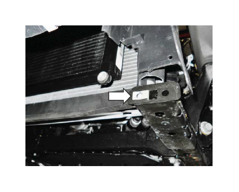
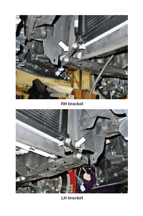
5. Install the RH LTR Support Bracket (1315-8K245) and LH LTR Support Bracket (1315-8K244) found in Hardware Kit H (1315-TVSHKH) on the lower tabs. Make sure to install the LH and RH in the correct position with the correct orientation. Secure each bracket at the radiator using a Bolt (W705128) and Nut (W520413). Secure each bracket to the chassis using a Bolt (W705128) through the J-Clip. Torque to 25 Nm.
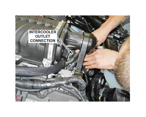
6. Temporarily install the LTR Outlet Hose (1315-8D030) on the upper LH side of the LTR radiator and route it to the intake manifold. Mark the LH radiator close-out panel where the hose should pass through. Use snips to cut a notch in the close-out panels as required for the hose to pass through.
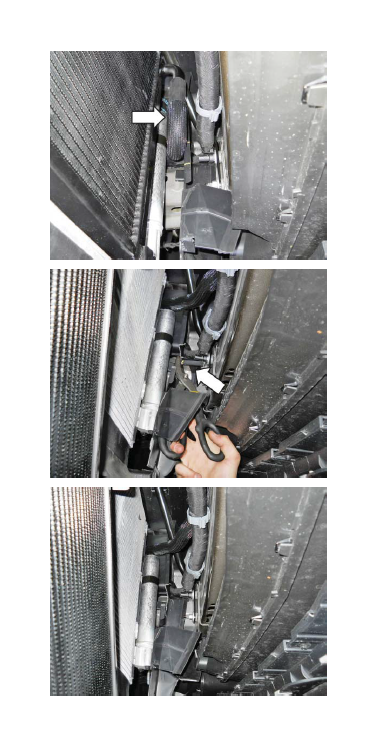
7. Reinstall the hose onto the LTR outlet, and recheck the hose fit. Adjust as necessary until the hose passes through the close-out panel without being kinked.
8. Once a proper fit is obtained, ensure the close-out panel is secure in place.
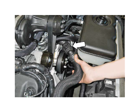
9. Install the LTR outlet hose through the close-out panel to the intake manifold.
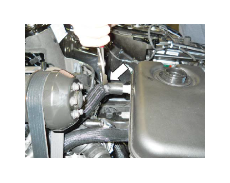
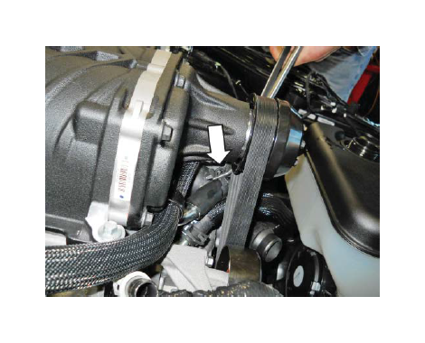
10. Install the hose onto the LTR outlet and secure it with the Clamp (CT19X12) from Hardware Kit G (1315-TVSHKG).
11. Install the hose onto the intake manifold inlet and secure it with the Clamp (CT19X12) from Hardware Kit G (1315-TVSHKG).
INTERCOOLER PUMP, MOUNTING BRACKET AND HOSES
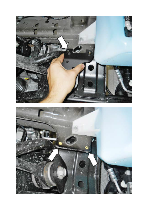
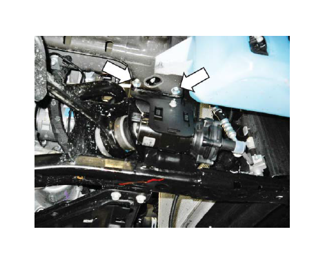
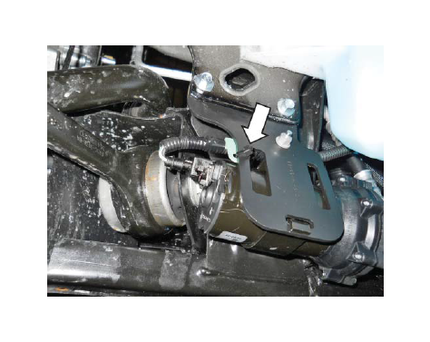
1. Using the Intercooler Pump Bracket (1315-8C4191) as a template, place the pump bracket against the frame behind the wiper fluid reservoir mounting bracket as shown. Mark the holes for drilling and remove the intercooler pump bracket.
NOTE: The bracket is placed on the outside of the frame behind the wiper pump reservoir bracket to make it easy to drill the holes. When installed, the intercooler pump and bracket will be mounted on the INSIDE of this section of the frame.
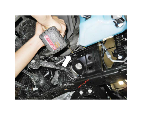
2. Start by drilling two (2) pilot holes. Then, drill out two (2) 3/8" holes.
3. Install the Intercooler Pump (F8YH-8501) into the Pump Retainer (R07070065-4G) and onto the intercooler pump bracket. Secure the pump and retainer to the bracket using one (1) M6 x 16 Bolt (N605891). Torque the bolt to 10 Nm.
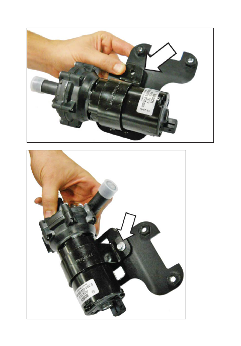
4. Place the intercooler pump assembly and bracket in mounting position with the pump in-board to the vehicle. Install two (2) Bolts (W500224) (M8 x 25) into the weld nuts. Torque to 25 Nm.
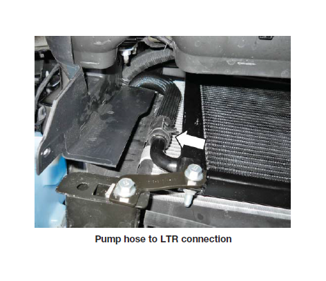
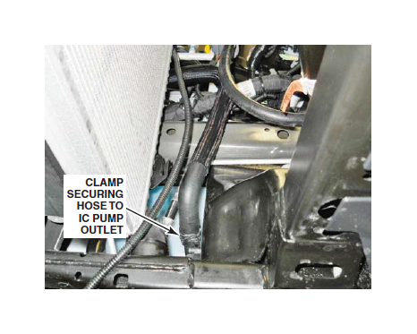
5. Install the intercooler pump outlet hose (1315-8K236) from the pump outlet, over the side of the frame rail and to the inlet on the lower RH side of LTR.
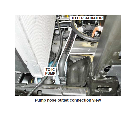
6. Secure the hose to the pump using one (1) Clamp (CT19X12) from Hardware Kit G (1315-TVSHKG). Secure the hose to the LTR inlet using one (1) Clamp (CT19X12) from Hardware Kit G (1315-TVSHKG).
7. Connect the intercooler pump harness electrical connecter to the intercooler pump and secure it with a zip tie to the bracket.
8. Collect the excess intercooler pump harness and secure it with zip ties as needed.
NOTE: Route all intercooler hoses very carefully. It is critical for intercooler performance that these hoses are not kinked once installed into the vehicle.
ELECTRIC FAN, INTERCOOLER RESERVOIR AND HOSES
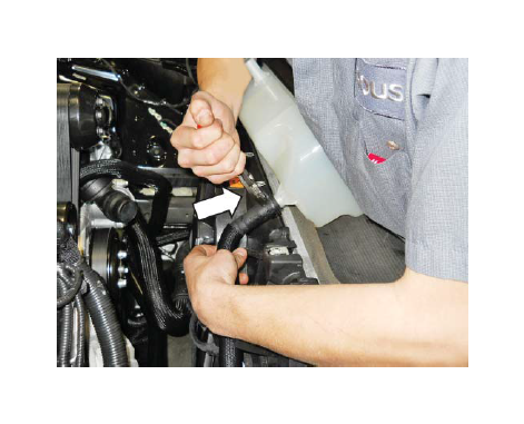
1. Install the electric fan in position and secure it with the two (2) mounting bolts previously removed. Torque to 10 Nm.
2. Connect the fan electrical connector.
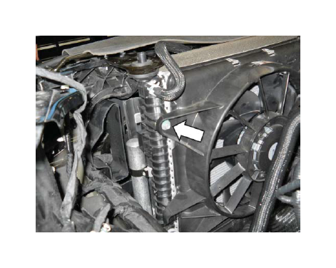
3. Ensure that the Clip (20860) installed during the electric fan modification is in place at the bottom of the Intercooler Degas Bottle (1315-8D080).
4. Install the Intercooler Pump Inlet Hose (1315-8D029) to the bottom of the intercooler degas bottle and secure it with the Clamp (CT19X12).

5. Install the intercooler degas bottle with Intercooler Degas Bottle Cap (9C3Z-8101) onto the fan shroud J-Clips. Push the bottle into position. The clip on the bottom should retain the degas bottle in place.
6. Install two (2) M6 x 1.0 x 22 mm Mounting Bolts (N605891) found in Hardware Kit H (1315-TVSHKH) and torque to 10 Nm.
7. Install the hose (1315-8D029) from the bottom of the intercooler degas bottle to the intercooler pump inlet. Secure the hose using (1) Clamp (CT19X12) from Hardware Kit G (1315-TVSHKG).
8. Install the Intercooler Degas Bottle Inlet Hose (1315-8D031) to the outlet on the intercooler.
9. Install the hose to the intercooler degas bottle inlet using (1) Clamp (CT19X12) from Hardware Kit G (1315-TVSHKG)
10. Install the hose to the intercooler cooler outlet using (1) Clamp (CT19X12) from Hardware Kit G (1315-TVSHKG).
RADIATOR HOSES, ENGINE DEGAS BOTTLE AND HOSES
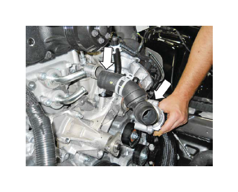
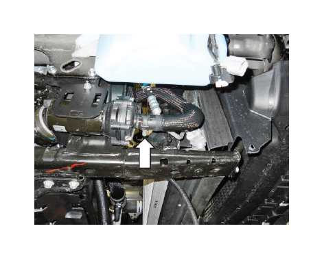
1. Reconnect the coolant hose to the outlet on thermostat housing.
2. Reconnect the other end of the coolant hose to the upper RH inlet of the radiator. Secure it with the clamp.
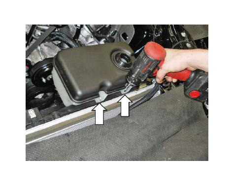
3. Reinstall the factory degas bottle onto the fan shroud and torque the bolts to 10 Nm.
4. Install the engine degas bottle hose on the rear of the bottle and to the upper LH radiator. Secure both ends of the hose with the clamps.
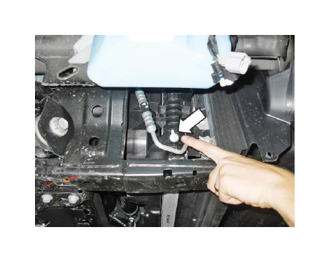
5. Transfer the hose clamp from the bottle end of the factory degas hose to new 3/8" Engine Degas Hose (1315-8276). Install the hose clamp (62002) onto the other end of the engine degas hose.
6. Install the 3/8" Engine Bottle Degas Hose from the engine degas bottle to the fitting by the driver side cylinder head on the coolant outlet neck. Tighten worm gear clamp torque to 3 Nm.
7. Install the other end of the hose to the engine degas bottle as shown. Secure the constant tension clamp.
8. Ensure that all intercooler hoses, the degas hose and all clamps and wiring have been installed to provide maximum clearance to the supercharger belt.
AIR INDUCTION SYSTEM
1. Remove the old MAF wire harness clip christmas tree that retained the harness to the body.
2. Install the Dirty Air Duct (1315-9F763) at the LH
side of the radiator.
3. Lower the airbox assembly into mounting position. Align the airbox assembly opening with the dirty air duct and press it into the dirty air tube until properly installed. A snap will be heard when properly seated.
4. Secure the airbox using the M6 bolt from the original airbox and torque to 10 Nm.
5. Install the Clean Air Tube (1315-9R504) in the vehicle using two (2) Hose Clamps (R07130015) from Hardware Kit A (1315-TVSHKA). Torque clamps to 3 Nm.
6. Install the PCV Fresh Air Inlet Tube (1315-6758) by connecting the 90-degree fitting to the driver side cam cover and angled fitting to the PCV fitting in the clean air tube.
7. Route the MAF wire harness around the airbox assembly and connect the harness to the MAF sensor. Make sure the red lock is engaged on the connector.
8. Connect the open end of the Supercharger Bypass Reference Line (7R3V-9E498) to the fitting on the clean air tube.
9. Connect the brake aspirator hose assembly (hose 3) to the fitting on the clean air tube.
K-BRACE
1. Once the supercharger installation process is complete, lift up the cowl trim panel and slide the modified K-brace underneath. Reinstall the K-brace over the studs and into position on the vehicle.
2. Install the nuts on the studs and torque to 25 Nm using a 15 mm socket.
3. Install the five (5) mounting bolts and torque to 25 Nm using a 13 mm socket.
4. Reinstall the six (6) pushpin retainers on the cowl trim panel.
SECTION E – FINAL ASSEMBLY
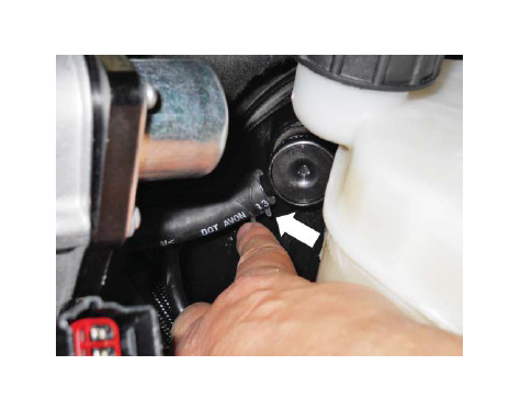
1. Fill the engine cooling system (using a proper coolant mixture) to the marked level on the radiator degas bottle.
2. Using the same coolant mixture, fill the intercooler system. The coolant should be approximately one inch below the top of the cap.
IMPORTANT: Both coolant systems can trap a large amount of air. It is very important to verify that the air is purged and that coolant is flowing properly through both systems. Ford Performance recommends vacuum filling both systems to properly evacuate the trapped air.
3. Reinstall lower close-out panel and inner fenders by reversing the removal procedures.
4. Reinstall the front wheels/tires. Torque wheel lugs to the factory Ford specifications.
5. Inspect all underhood wiring harnesses for potential interference issues. Use zip ties to safely position the harness away from any areas of concern.
6. Reinstall the radiator trim cover by reversing the removal instructions.
DO NOT ATTEMPT TO REINSTALL THE PCM AND START THE VEHICLE IF THE PCM IS NOT EQUIPPED WITH A FORD PERFORMANCE CALIBRATION. OPERATING THE ENGINE WITHOUT THE RECALIBRATED PCM WILL RESULT IN ENGINE DAMAGE OR FAILURE AND WILL VOID THE WARRANTY.
7. Reinstall the battery connections by connecting the positive cable first then connecting the negative cable. Reinstall the battery cover panel with pushpins.
8. Reconnect the fuel pump control module electrical connector located under the backseat on the driver side.
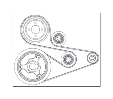
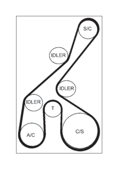
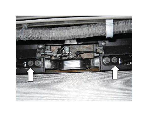
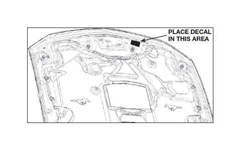
9. Place the Belt Routing Diagram (13116E072) found in Hardware Kit F (1315-TVSHKF) on the underside of the hood, on the driver side, opposite of the factory Vehicle Emission Control Information decal.
10. Place the PCM Decal (R07100008) found in Hardware Kit F (1315-TVSHKF) in a visible location.
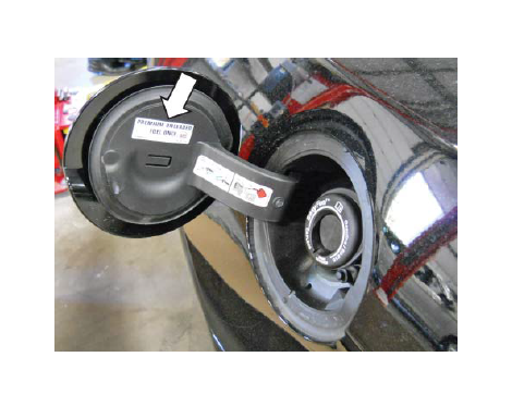
11. Place the “PREMIUM FUEL ONLY” Decal (13109A095) (white decal with black lettering) found in Hardware Kit F (1315-TVSHKF) on the arm door of the fuel filler door as shown.
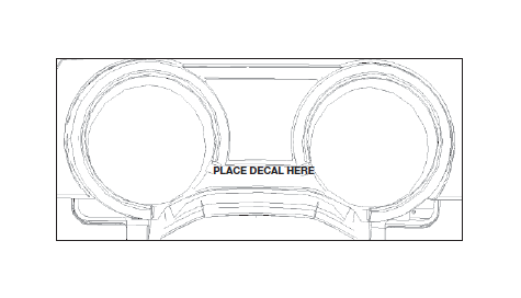
12. Place the “PREMIUM FUEL” (R07110004) Clear Decal with white lettering on the instrument cluster bezel, on the flat area below the small center gauges as shown.
13. Place the E.O. label (CM-EO-M8627) in a visible location under the hood. (Top of airbox lid or side of strut tower.)
14. If performing the PCM Flash procedure, proceed to the “PCM Flashing” section.
PCM FLASHING
1. Refer to the documents in the calibration interface tool (CM-CANTELOPE-B) and on the Ford Performance calibration voucher (CM-0800- PC103). The manual will guide you through the PCM flashing procedure. OPERATING THE ENGINE WITHOUT THE RECALIBRATED PCM WILL RESULT IN ENGINE DAMAGE OR FAILURE AND WILL VOID THE WARRANTY.
2. Once the PCM has been successfully re- calibrated, start the engine and check for unusual noises, dash service lights, and unusual operation. If problems are detected, immediately stop the engine or vehicle, diagnose and repair the problem.