 FREE 1 to 3-Day Delivery on Orders $149+ Details
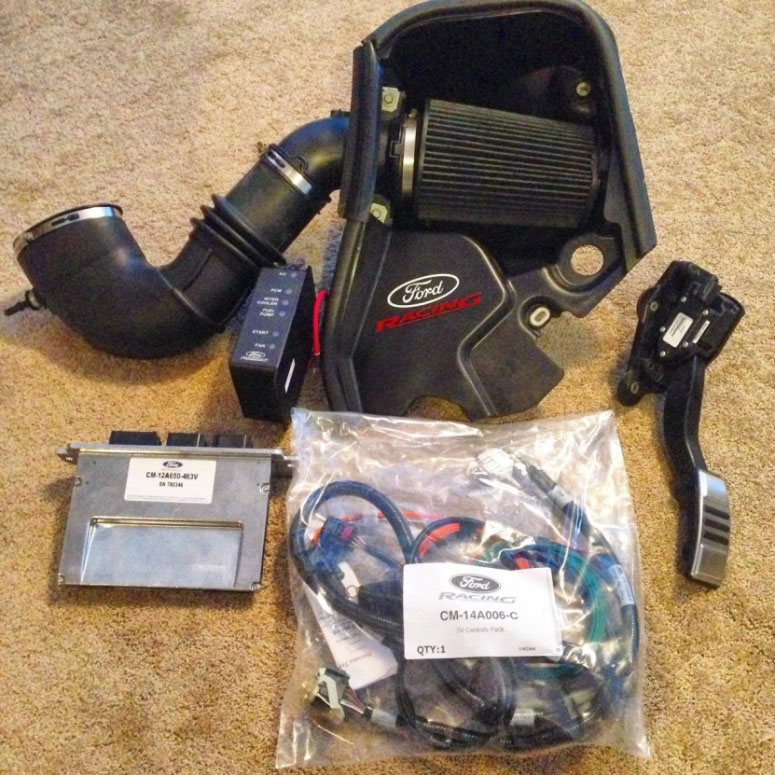
How to install a Ford Racing 4.6L 3V Crate Engine Control Pack on your Mustang
Installation Time
1 days
Tools Required
- Basic English and Metric Socket and Wrench Set
- Flat and Phillips Screwdrivers
- Torx bits
- Hammer and punch
- Drill and drill bits
- Vise (For pedal bracket)
- Cut off wheel or SawZall
- Pliers
- Soldering Iron, Solder, and Flux
- Wire Cutters
- Wire Stripper
- Wire Crimper
- Shrink tubing
- Masking Tape(Recommended)
- Electrical Tape
- Multi-meter
Installation Time: 3-6 hours on a Foxbody Mustang
Tools Required:
• Basic English and Metric Socket and Wrench Set
• Flat and Phillips Screwdrivers
• Torx bits
• Hammer and punch
• Drill and drill bits
• Vise (For pedal bracket)
• Cut off wheel or SawZall
• Pliers
• Soldering Iron, Solder, and Flux
• Wire Cutters
• Wire Stripper
• Wire Crimper
• Shrink tubing
• Masking Tape(Recommended)
• Electrical Tape
• Multi-meter
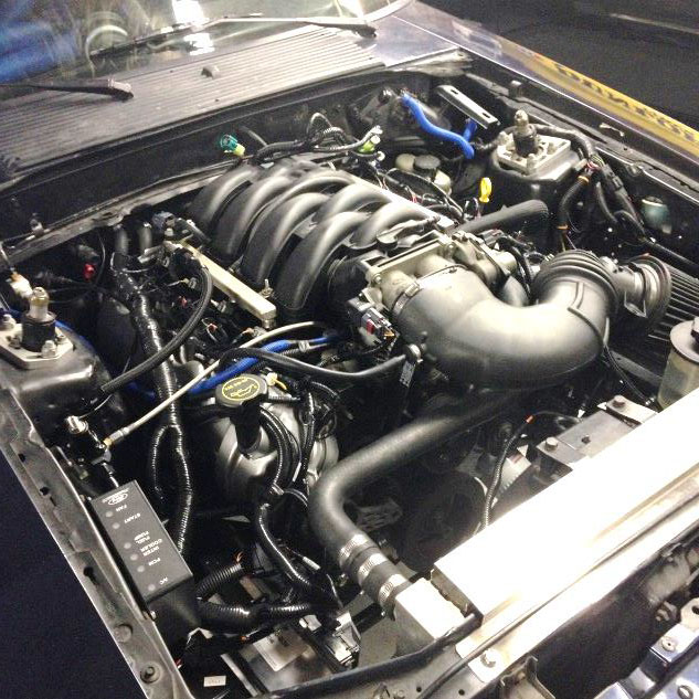
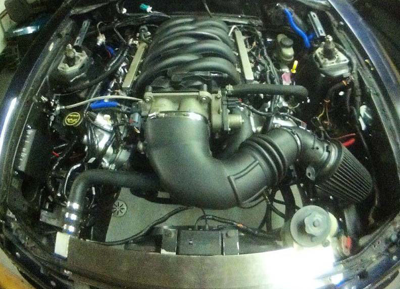
This installation guide assumes that your 4.6L 3V engine is already installed in the vehicle and all mechanical systems, such as transmission, clutch, exhaust, charging, cooling, power steering, and fuel pump and lines are already complete and installed. It is also assumed that the factory ECU and related harnesses are removed.
1. If it hasn’t been removed already in order to remove the factory ECU and harnesses, remove the passenger side door sill and kick panel trim to later access the kick panel area.
2. Unfortunately, the base of the cold air kit that would normally fit right on a 05-09 4.6 3V, cannot be used. Remove the Mass Air Flow housing from the base by unbolting the two 10mm bolts.
3. Install the MAF sensor into the MAF housing with the provided Torx fasteners.
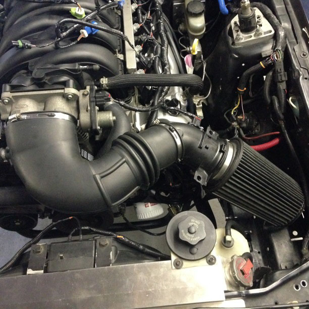
4. Install the intake tube onto the throttle body and tighten with either a flat head screw driver, or 5/16” socket.
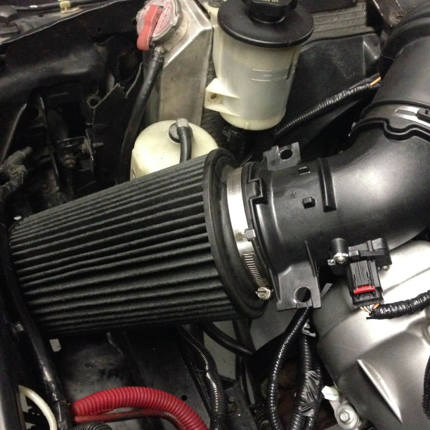
5. The long filter provided just squeezes into the area where the battery usually is on a Fox body. Connect the mass air flow connector.
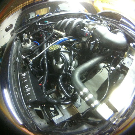
6. Layout the Ford Racing CM-14A006-C harness after connecting the engine harness, Power Distribution Box (PDB), and PCM connectors. The location of the PCM and PDB will be typical on this installation, the passenger front apron area, or where the air filter box usually is on a Fox body Mustang.
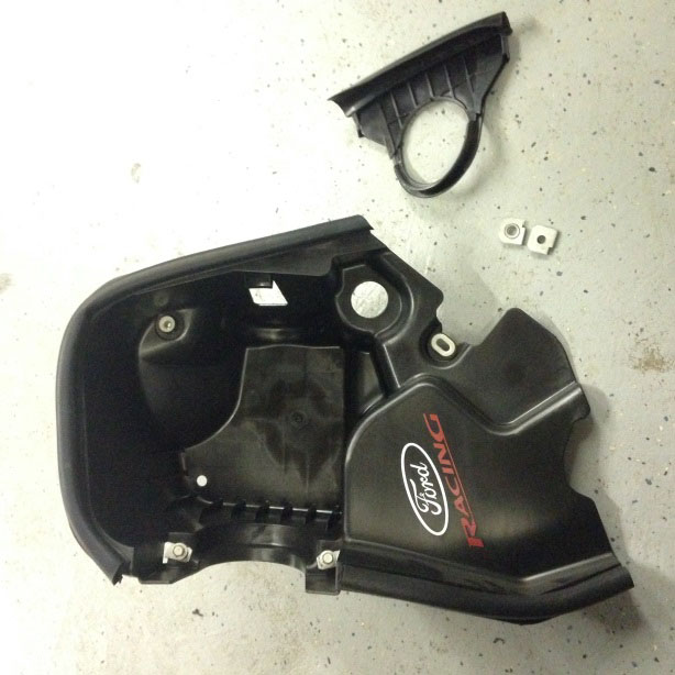
7. A factory PCM bracket (not included) from a 05-09 Mustang will be slightly modified to make the mounting of the PCM much simpler.
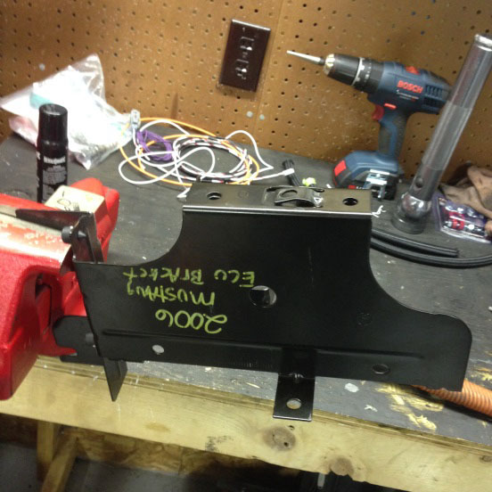
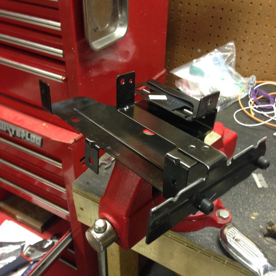
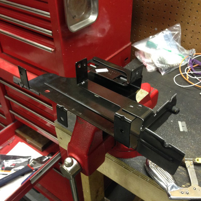
After portions of bracket are removed
8. Using an appropriate metal cutting tool, remove the portions of the PCM bracket. (left) Remove any sharp edges.
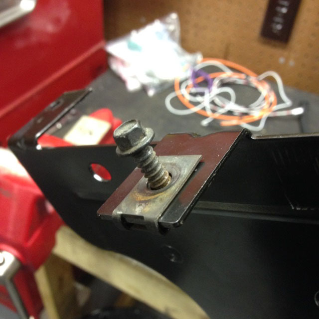
9. Bend one portion of a tab at 90 deg. for fitment in the car (left). The tab shown happens to work out perfectly for mounting to the passenger apron rail. Use an appropriate fastener and J nut similar to the hardware shown above, right.
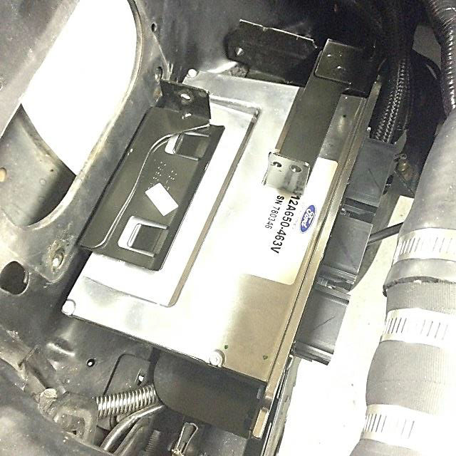
10. Place the PCM in the bracket, place and mark where a hole will need to be, using the tab hole as a template. The hole will need to be drilled big enough for a bolt to pass thru.
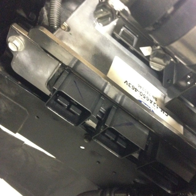
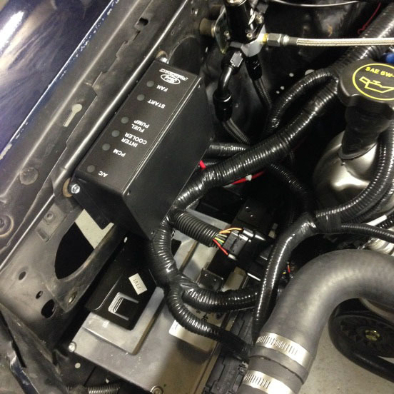
11. Install the PCM in the bracket using 10mm bolts and install the PCM and bracket using the hardware chosen (left).
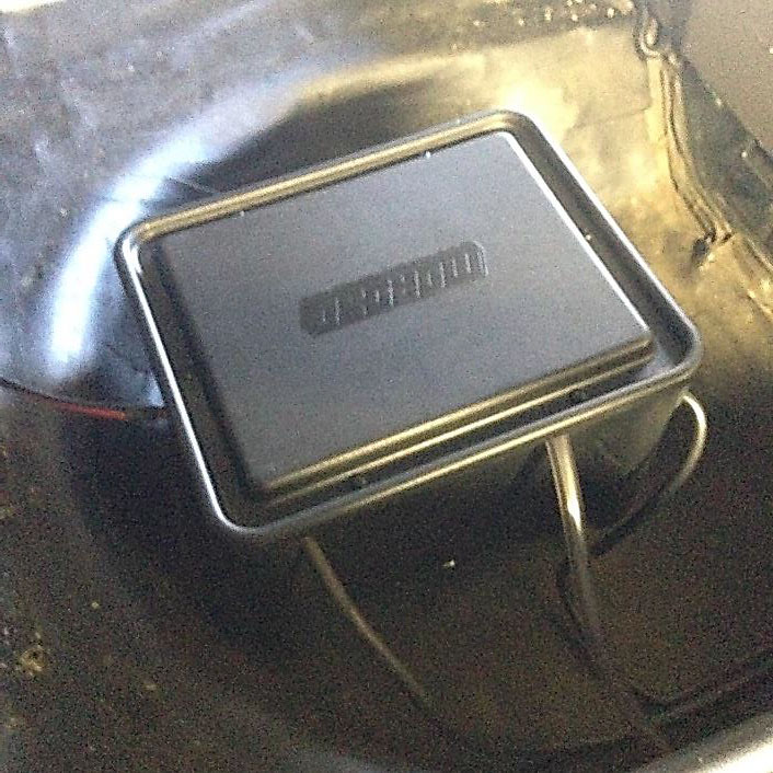
12. Using self-tapping screws or another method, mount the PDB with rubber isolators to the apron (right).
Now, correctly extending the Accelerator and OBD harnesses involves some soldering. 28 total solder connections to be exact, not including connections you need to solder for the 12V, Fuel Pump, etc.
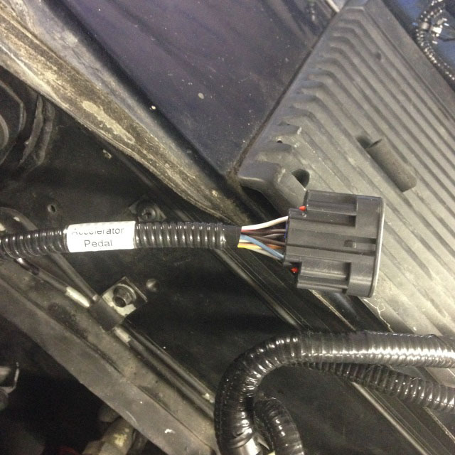
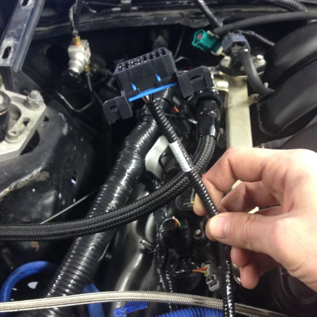
13. This is as far as the Accelerator Harness (left) and OBD II (right) harnesses reach.
14. Pull back the tape and loom for the connectors to expose the wires to cut. Make sure to give yourself at least 2” of wire from the connector.
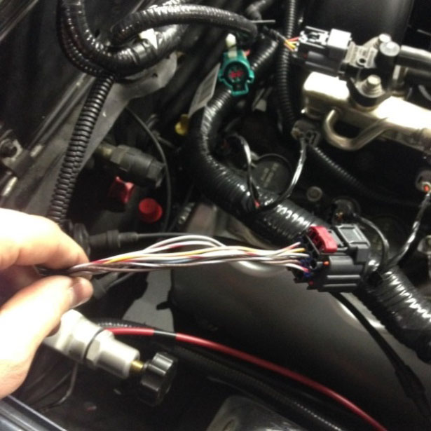
15. Finding the exact wire and tracer color can be difficult. Using mostly white wires is acceptable. Labeling the wire and tracer colors at the end of the new extension wire is necessary to make certain the corresponding wires are correct. Each harness needs at least another 2 feet of wire to be long enough to reach the components. Routing a single wire from the severed connection thru the engine bay, and into the passenger cabin, to the destination is recommended beforehand to know exactly how much the harness will need to be extended.
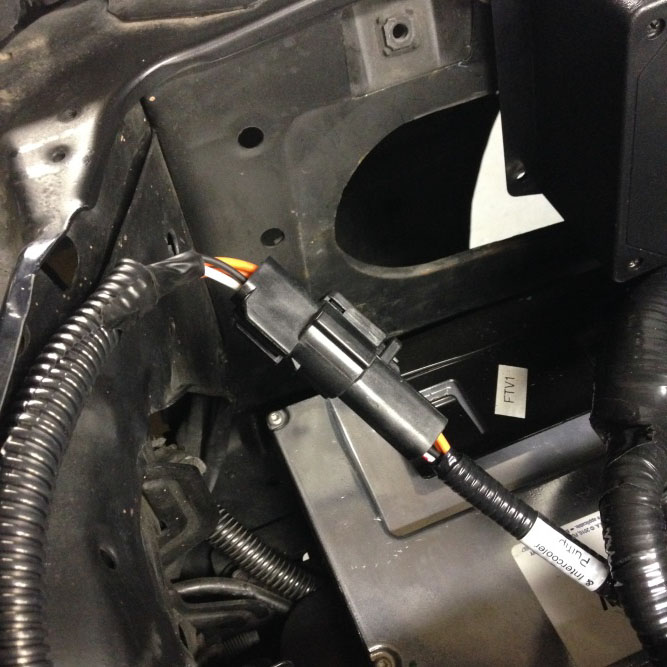
16. After making the extensions, route the pedal and OBD II connector harnesses thru the firewall and into the passenger compartment. Mount the OBD II connector where desired. Left of steering column typical.
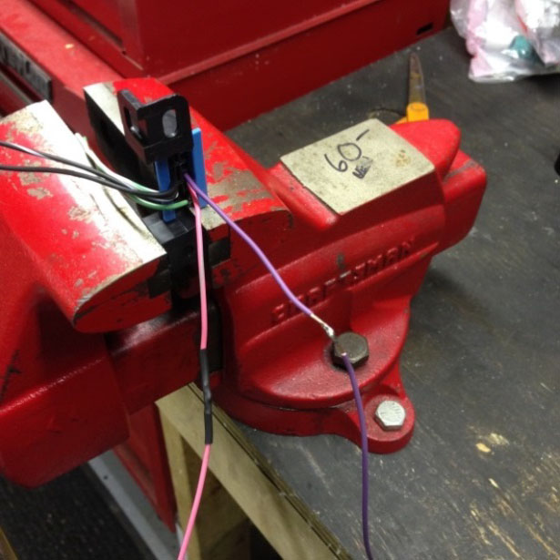
You can easily remove the wire from the connector with a small pocket screwdriver and release the connector pin instead of just cutting it and leaving a nub of wire
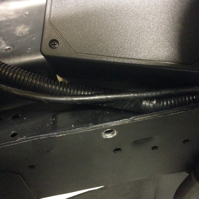
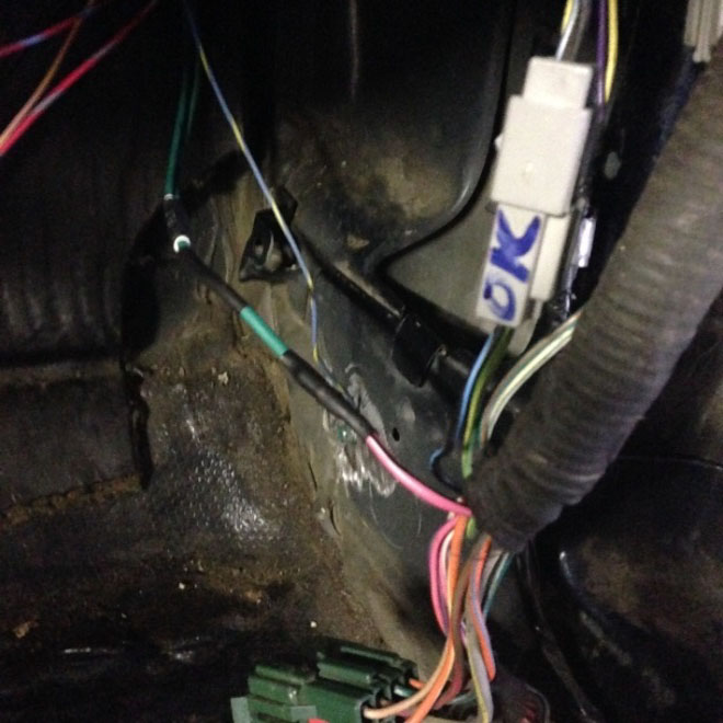
17. The blunt wire harness provided is labeled but after routing the harness thru the firewall where the stock computer harness goes thru, you’ll never see the labels. It’s best to label them yourself, instead of having to keep on referencing the Ford diagrams. Route the blunt lead harness thru the firewall and into the passenger compartment kick panel.
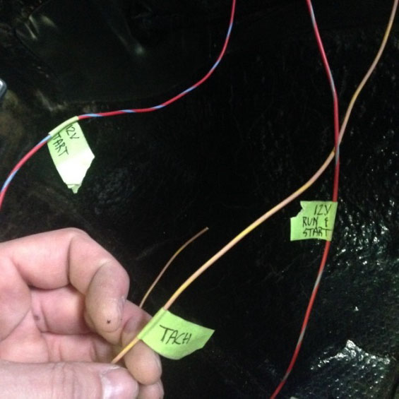
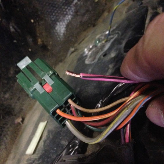
18. Create the solder connections for the 12V in run (12V source when the key in in the On or Start position), 12V in start pos. (optional, but recommended to let the PCM control the starter), and tachometer leads (Left). The fuel pump wire (Pink w/ black tracer) is part of an existing green connector that was part of the factory ECU connections and is in the passenger kick panel. It connects to the fuel pump relay that’s under the seat, so you don’t have to route the wire all the way to the relay, let alone the fuel pump itself. (Right)
Fuel pump wire soldered with shrink tubing
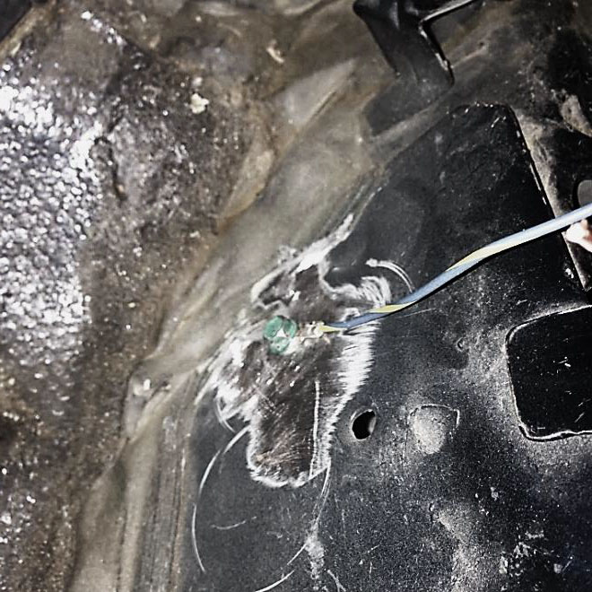
Clutch switch wire grounded near kick panel
19. Create the solder connection for the fuel pump lead.(left)
20. The clutch safety switch lead needs to be grounded or hooked up to a clutch switch that is normally open then grounded when pushed. Using an eyelet connector, and a good ground to the chassis, connect the clutch safety wire.
21. As per Ford Racing, the Power Leads and Ground must be connected directly to the battery positive and negative terminals, respectively. In this case, the battery was relocated to the rear of the car. This also means that those leads must be lengthened to reach the battery. Using 8 and 10 gage wires lengthen the power and ground wires to make the connection to the battery.
Power and ground leads directly to battery
Electronic Accelerator Pedal
22. The pedal that comes with the kit has the large standard, plastic mounting plate that most definitely will not bolt, let alone fit, under the Fox dash. Luckily, that big plastic mount unbolts from the pedal assembly.
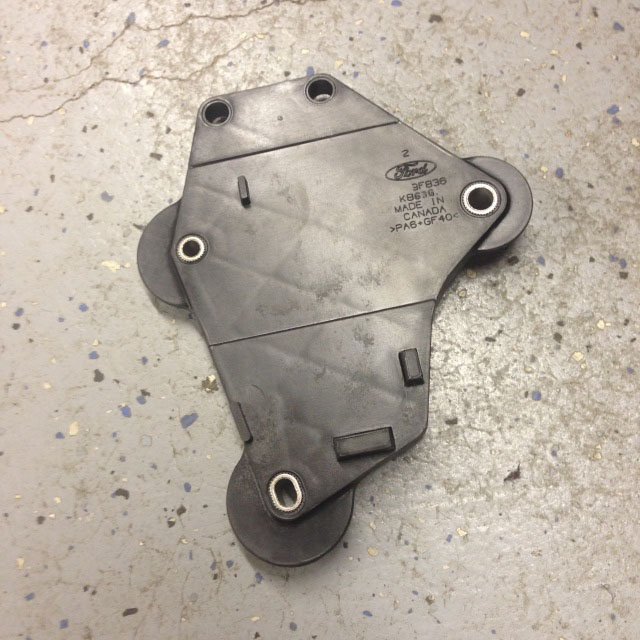
Large mounting plate removed from pedal with brass nut inserts removed to be used
Brass nut inserts. Fox pedal bracket modified to fit new pedal
23. Unbolt the Allen screws from the pedal assembly and remove the pedal from the mount. Remove the brass nut inserts using a punch and hammer to drive them out.(left)
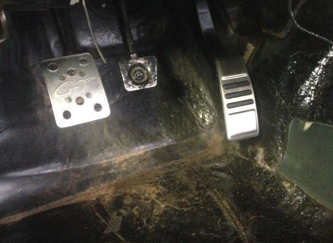
24. Modify the factory Fox pedal bracket to match the bolt pattern of the top to bolt holes of the pedal assembly.
25. Use the brass insert nuts and Allen screws removed from the mounting plate to mount the pedal assembly to the modified bracket before installing the whole assembly in the car.
• Getting the tabs correct on the Fox pedal bracket that the pedal mounts to, will involve some trial and error. The tabs need to be at the right angle so that the pedal will not only be in a good position, but also enable the pedal to reach WOT.
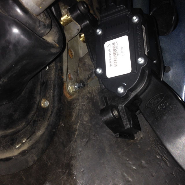
26. Connect the accelerator pedal harness to the pedal
Fuel System
In order to provide the engine with a return style fuel system, you’ll need a few things. The Aeromotive Bypass Regulator (P/N 13129) for the fuel regulator is a one choice. Russels brand fittings make going from Ford fuel line connections at the Fox pressure, return line, and 3V fuel rail (P/N 640883 x 2 & 640873 x 1) to AN style fitting a breeze. This eliminates the need to cut any stock fuel lines. How you want to route the pressure return and fuel rail feed is up to you, but below is how this application was mounted and the lines routed. The regulator does not come with adapters so you’ll need 1, 6 ORB to -6 AN and 2, 6 ORB to -8AN adapters.
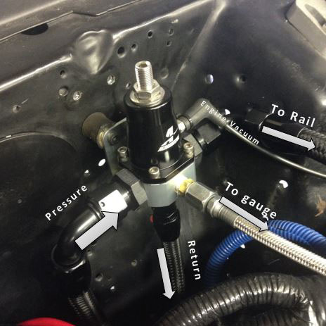
27. Make the fuel connections similar to above.
• At this point you should be able to turn the key and test the fuel pump.
• While the pump is running (it will always be running when the key is in the ON position) set the fuel pressure to 40PSI with the regulator.
• Check for any fuel leaks. If there are any leaks, repair them before proceeding.
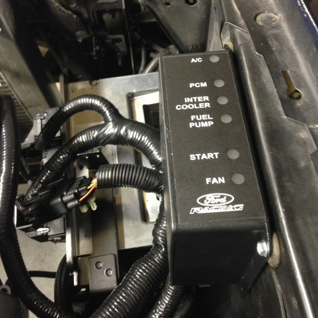
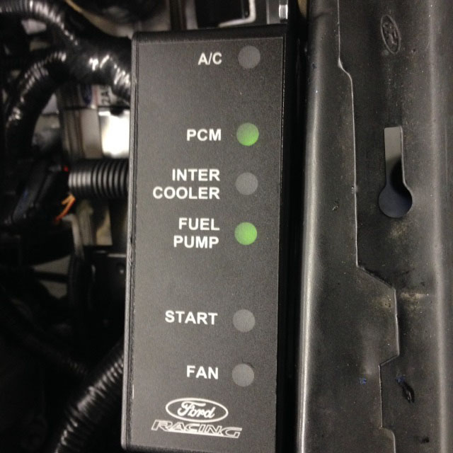
28. With the key in the ON position the PDB should have the PCM and Fuel Pump lights on.
Starter
29. The PCM can control the low amperage side of the starting circuit, as long as the 12V in Start lead was connected correctly. The starter lead is part of engine harness, but the starter cable still needs to be connected. The stock Fox starter cable will work when hooked up to the other side of the solenoid.
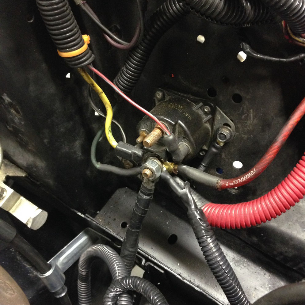
Starter cable connected to the same solenoid as the battery cable
Cooling Fan
The PCM can also control when the cooling fan turns on and off. It will provide 12V when there is the need for the fan.
30. Make the connections using the orange wire from the Intercooler Pump/Cooling Fan harness.(above)
• The cooling fan will still need to be provided a ground. Make that connection either directly to battery or chassis ground.
O2 Sensors
The O2 sensor connections are part of the engine harness (not provided).
31. Install the O2 sensors into the exhaust bungs using a 7/8”/22mm wrench
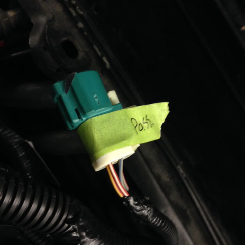
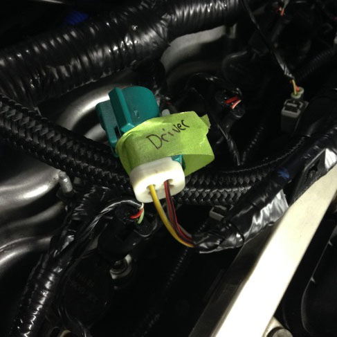
• TIP: The Passenger side O2 sensor connector on the engine harness has a Grey/Blue wire. Driver side connector has a Red/Black wire. It’s important that the correct side gets connected to the corresponding sensor; otherwise Closed-Loop fuel control will not function properly.
32. Connect the O2 sensors.
33. Ensure that all fluid levels are topped off before initial startup.
34. Start the engine and allow it to get to operating temperature
35. Check for any leaks. Enjoy the 3V!
A couple of pointers from I learned from Ford Racing.
• The PCM doesn’t need oil pressure input. Even though the stock engine harness hooks up to the oil pressure sending unit, that’s just for a factory S197 gage. Since most gear heads would want to know the oil pressure of their engine, you can omit the stock sending unit and install whatever aftermarket sending unit in its place. The 100PSI Autometer sending unit for 0-100 Electric gages fit perfect at the stock location with an adapter that is included with the Autometer 260 deg. water temp sending unit. I did have to drill and tap the coolant crossover to implement a water temp sending unit.
• There’s no way to simply add cruise control. I was hoping that maybe adding switches like the S197s’, it would be simple, but Ford said there is no way but perhaps an aftermarket type of solution.
• The control pack will support a cooling fan that draws up to 40 amps. Any fan requiring more than 40 amps will require a relay between the control pack’s 12V feed and the fan.
• Like many car’s, you may have a rear mounted battery and Ford fully insists that the main ground and power connections be directly to the battery. This means those leads will more than likely be lengthened as well to reach the battery.
Installation Instructions Written By AmercianMuscle Customer Matt Soppa 3/3/2015
