 FREE 1 to 3-Day Delivery on Orders $149+ Details
How to Install GMS Sub-Frame Mount Set on your Mustang
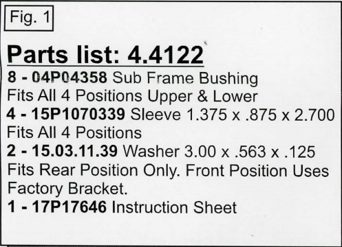
ATTENTION: We recommend acquiring a Ford factory workshop manual for all warnings and procedures to safely remove and install the drive shaft, wheels, rear shocks, brakes and rear sub frame. Or go online to www.helminc.com forap Online Service Information Subscription. Ford requires replacement of all hardware with any self-locking feature. Refer to the factory workshop manual for examples of self-locking nuts and bolts. This instruction set is intended as a guideline for the safe installation of Energy Suspension's polyurethane sub frame bushings, once you have removed the factory rear sub frame from your vehicle. Check that the parts you received in this kit match the parts list on page 2
(Fig. 1) A transmission jack will be needed for lowering and lifting the rear sub frame and a portable 10 ton hydraulic pull back ram to be used for removal of the factory rubber bushings. This hydraulic ram should be available from any tool and equipment rental company in your area.
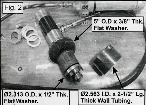
(Fig. 2) Remove the complete exhaust system from the catalatic converters to the tail pipes. Disconnect the differential vent tube located on top of the differential cover. Index mark the O.E. rear sub frame bushings for reference during installation
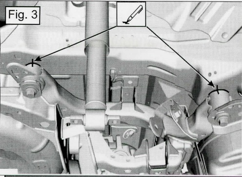
(Fig. 3) Index mark the driveshaft and the pinion flange for reference during installation.
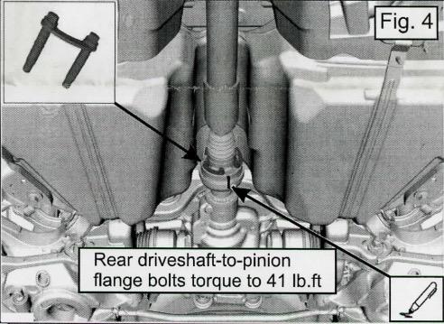
(Fig. 4) Remove the 4 forward bracket bolts and the 4 sub frame mounting bolts and set aside. All 4 factory rubber bushings are the same size and will require the same setup to remove.
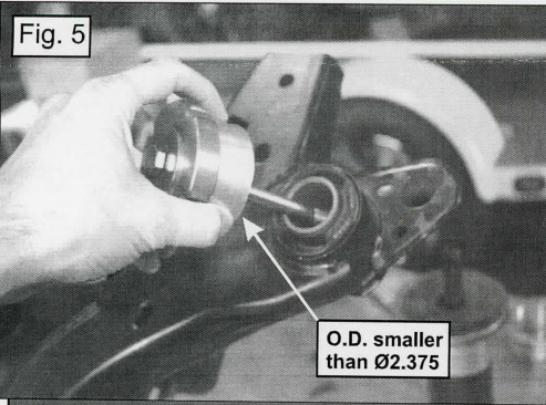
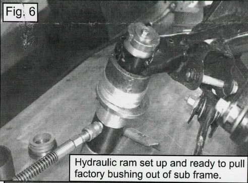
(Fig. 5 & 6) The outer metal shell of the factory rubber bushing must be pressed out.
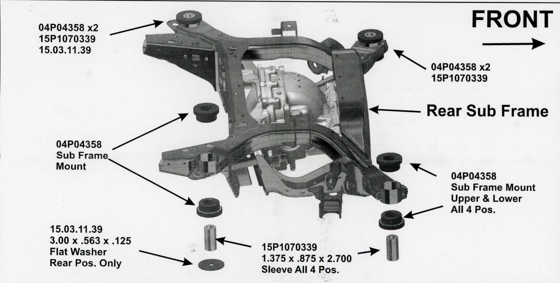
(Fig. 7) After all 4 factory rubber bushings have been removed, remove all sharp edges that will contact the polyurethane bushings on the sub frame. Install the new polyurethane bushings as shown in the parts diagram above. Reinstall the sub frame according to the factory workshop manual. Use a thread locker compound on the threads of the bolts during installation. Reposition the sub frame and install the sub frame mounting bolts and front bracket bolts finger tight. On both sides align the sub frame index marks made during removal.
(Fig. 8) Tighten the 4 rear sub frame bracket bolts and torque to 41 lb.ft.
(Fig. 9) Tighten the 4 rear sub frame forward bolts and torque to 129 lb.ft.
(Fig. 10) Reconnect the differential vent tube. Position the driveshaft to the pinion flange and align the index mark made during removal. Install the driveshaft-to-pinion flange bolts and torque to 41 lb.ft. After completing the installation, double check that all hardware has been properly torqued to factory specs. You should periodically inspect all hardware and components and replace any damaged components as necessary to maintain the reliability of your vehicle.
*Note: Installing firmer polyurethane subframe and/or differential bushings will increase NVH and driveline noise.
