 FREE 1 to 3-Day Delivery on Orders $149+ Details
How to Install Hurst Competition Plus Shifter - MT-82 on your Mustang
Tools Required
- Ratchet
- 10mm Deep Socket
- Long Extension
- Pliers and cutting pliers
- Trim Tool
- Wire stripper/crimper
- Hex Wrench 5/16”& 7/32"
- Jack Stand
- Electrical Tape
- Drill & ¼ Drill Bit
- Floor Jack
- Wrenches 10mm & 5/8"

Shop Parts in this Guide
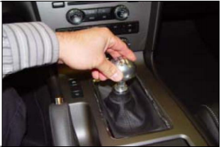
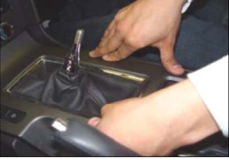
1. Unscrew the shift knob.
2. Open the center console storage box and starting from the back carefully unsnap the center console trim cover/cup holder unit from center console by firmly
grasping the back edge and pulling directly upward.
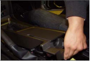
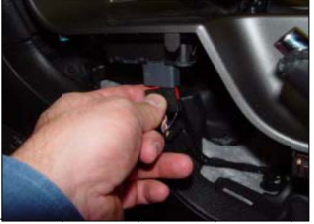
3. Disconnect the traction control/hazard light /trunk release and any other (cup holder, lightning, etc.) wiring harness cnnectors that prevent removal of this center console tripm plate. Then remove the consol trim plate.
NOTE: It may not be necessary to completely disconnect all wiring harness and instead let the trim plate hang off the side,
4. Remove the rubber boot that seals the shifter to the tunnel.
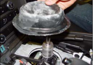
5. Remove the three (3) accessible screws of the four (4) screws holding the shifter to the shifter linkage housing.
NOTE: The forth screw is difficult to access from inside the vehicle and will be removed in step 9.
TOOLS: 10mm Deep Socket, Ratchet, & Extension
6. Carefully raise car for under vehicle acces .
TOOLS: Floor Jack & Jack Stands
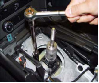
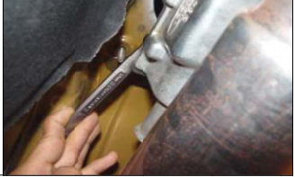
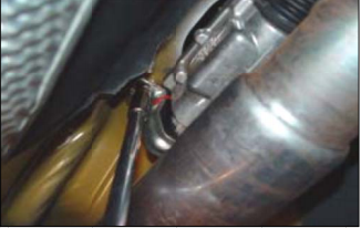
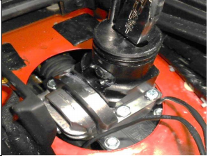
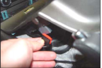
7. From underneath the vehicle, unscrew the two (2) mounting nuts holding the rear shifter support
bushing bracket.
TOOLS: 10mm Deep Socket, Ratchet, & Extension
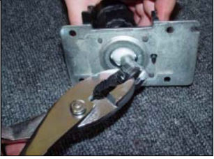
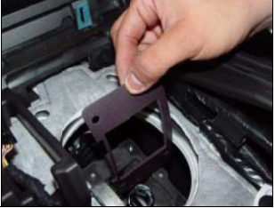
8. Pull the rear bushing bracket off of the tunnel studs. Then firmly work the bushing off of the shifter
housing and remove the rear bushing assembly from vehicle.
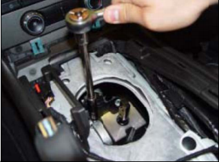
9. Unscrew the remaining shifter mounting screw.
TOOL: 10mm Wrench
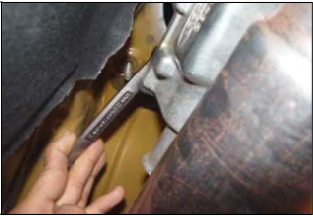
10. From inside the vehicle, remove the shifter.
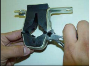
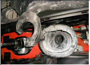
11. Trim the tie wraps from the rear bushing assembly,
remove the rubber bushing from the bracket.
TOOL: Cutting Pliers
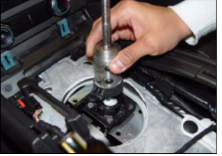
12. Pry off the lower bushing cup off of the shifter bottom pivot, being careful not to damage the soft plastic as this part will be re-used.
TOOL: Pliers
13. Grease the lower pivot ball of the Hurst shifter
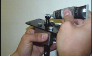
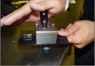
14 . Place the plastic bushing cup (removed in step 12) onto to a hard surface and snap the lower pivot ball of the Hurst shifter into the bushing cup.
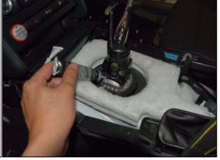
15. From inside the vehicle place the supplied Foam Gasket onto the shifter housing base.
NOTE: Position the long notch on the side of the gasket toward the driver and the small notch toward the rear of the vehicle.
16. Place the Hurst Shifter on top of the foam gasket and shifter housing base and tighten the three (3) accessible screws.
NOTE: Position the long notch on the side of the shifter toward the driver and the small notch & Hurst logo toward the rear of the vehicle. The fourth screw is difficult to access from inside the vehicle and will be installed in step 19.
TOOLS: 10mm Deep Socket, Ratchet, & Extension
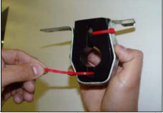
17. Insert the supplied polyurethane rear bushing into the rear bushing bracket and secure it with the two supplied tie wraps. Trim the excess ends.
TOOL: Cutting pliers
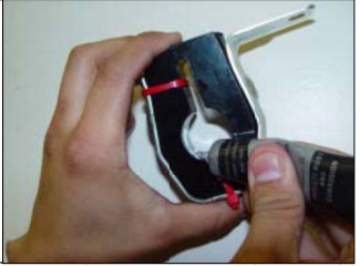
18. Using the supplied grease, lubricate the inside of the polyurethane bushing.
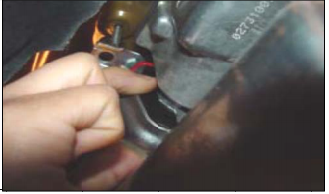
19. From underneath the vehicle, install the 4th mounting screw securing the Hurst Shifter to the shifter housing base.
TOOL: 10mm Wrench
20. Push the rear bushing assembly onto the rear of the shifter base assembly.
NOTE: The longer bracket ear should be installed on the driver’s side to center the shifter in the tunnel.
21. Push the rear bushing assembly onto the mounting studs and tighten the mounting nuts to secure the shifter assembly to the tunnel.
TOOLS: 10mm Deep Socket, Ratchet, & Extension
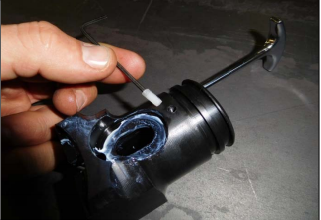
22. Insert the Trigger Rod into the Reverse Lockout Collar
23. Insert the cotter pin through the hole in the Trigger Rod. Bend each leg of the cotter pin 90 degrees and cut excess material. The photo to the right is a bottom view of the assembly. Please Note orientation of the cotter pin and the approx. lenght of the legs.
Tools: Needle Nose Pliers, Wire Cutters
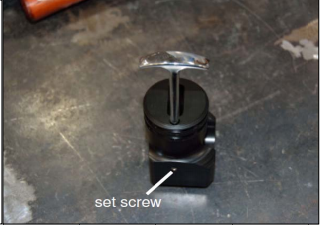
24. Align the Trigger Rod so that the top is perpendicular to the opening in the Reverse lockout Collar. While maintaining the alignment, pull up on the Trigger Rod so that it is at its highest position within the Reverse Lockout Collar and secure it in position with the steel set screw.
NOTE: Add a drop of loctite th threads of set screw to prevent sete screw
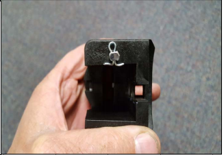
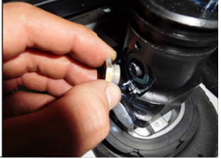
25. Thread one of the supplied nylon set screws into
the upper hole on the left side of the block. Screw it in until it just begins to protrude into the slotted center
opening.
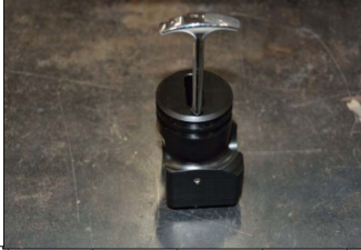
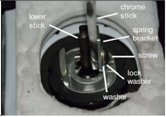
26. Install the Upper Chrome Stick and Spring Bracket. The 3/8” guide screw will be inserted and installed into the bottom hole of the stick along with a 3/8” lock washer and a 3/8” washer.
Tool: 7/32” Allen Wrench
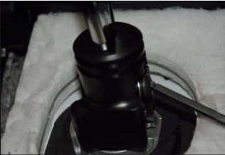
27. Slide the reverse lockout block down over the shifter and install the second 3/8" bolt into the top hole of the chrome stick.
28. Install the extension spring to the Reverse Lockout
Collar with the supplied Spring Retaining Screw.
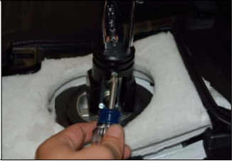
29. Insert the other end of the spring onto the Spring Bracket tab.
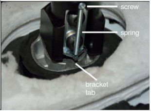
30. Add grease to the Lockout Collar where it rides
against the guide nut.
Add a drop of Loctite to the internal threads of the guide nut and install onto the end of the upper screw. Test the Reverse Lockout Collar for proper function. Pull up on the trigger rod and release. The collar should spring back to its lowered position.
Tools: 5/8” Socket, Ratchet
31. Use an allen wrench to adjust the nylon set screw that was installed in step 25. Adjust as necessary to reduce side to side play and get the block to slide up and down freely. Once it’s adjusted properly insert a second
nylon set screw and tighten against the first to lock in place.
32. To prevent premature wear to the the Reverse Lockout Collar, apply grease to the shifter reverse block and lock-out collar where the two will contact during shifts to 1st /
2nd gear.
33. There reverse lockout must be adjusted so that the shifter can smoothly be shifted into first gear while not being able to shift into reverse without pulling up on the
T handle. Adjustment can be made by sliding the lockout and securing it into position by tightening down the 4 bolts.
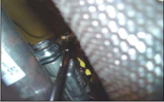
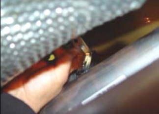
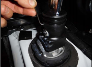
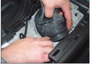
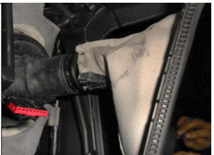
34. The bottom of the factory rubber boot will need to be trimmed in order to clear the Hurst shifter.
35. Worh the rubber boot seam onto the shifter access-hole edge so that it fully seals the tunnel hole.
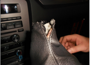
36. Carefully peel the leather shift boot away and off of the plastic boot collar. The plastic collar will not be re- used.
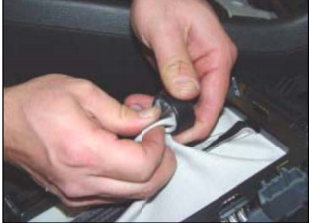
37. The factory shifter boot will need to be opened up
in order slide it over the reverse lockout. Start by cutting loose enough threads so that the boot will slide over the lockout with a snug fit.
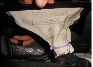
38. Invert the shift boot and slide it over the reverse
lockout.
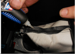
39. Although the zip tie installed in the next step should
prevent any further unraveling to the sewn seam of the shift boot, you can place a small amount of super glue (not supplied) onto the stitching to keep it from unraveling.
40. Locate the upper groove in the reverse lockout and use the supplied tie wrap to secure the boot in place.
41. Reconnect the traction control/hazard light/trunk release and any other (cup holder lighting, etc.) wiring harness that had disconnected.
42 . Snap the center console trim cover/cup holder unit back into place.
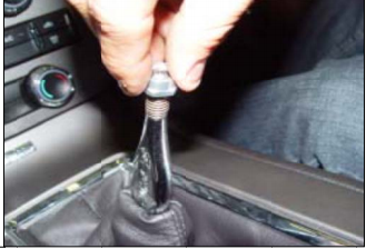
43. Screw the jam nut down onto the upper stick threads.
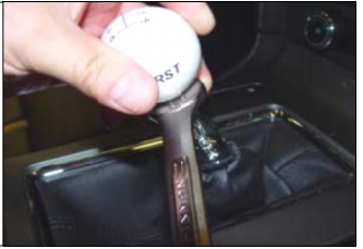
44. Install the shift knob onto the stick. Align the logo on the shift knob accordingly and tighten the jam nut up against the knob. A few drops of Loctite will help prevent the knob from loosening.
CAUTION! Over tightening the knob down onto the stick will eventually cause the knob to crack.
A LOW LOCTITE TO DRY.
Tool: 5/8” Wrench
45. Before operating the vehicle, test the shifter
through all gears making sure that each gear, including reverse, can be engaged fully and smoothly without rough movement or binding. Also, ensure that the shifter fully and smoothly self-centers in the neutral position and does not hang in the reverse, 1st-2nd gear, or 5th-6th gear plane. Correct any problems before operating the vehicle. Start the vehicle and carefully test engaging first gear and the reverse gear. Ensure that the reverse lights illuminate when the reverse gear is selected.
WARNING! Failure to easily distinguish between first and the reverse gear can result in damage, injury, and/or death.
