 FREE 1 to 3-Day Delivery on Orders $149+ Details
How to Install IAT Relocation Kit on Your 2005-2010 Mustang
Installation Time
1 hours
Tools Required
- 3/8-inch NPT Tap (this is looks like a tapered drill bit, you insert it and screw it into a hole. This creates threads so that the IAT sensor can be installed. Just ensure you use an NPT and not an NC tap. The 3/8-inch NPT can be little hard to find, you can try online or your local plumbing and heating store. Most hardware stores like Home Depot will only carry NC taps. Auto parts stores will carry NPT taps but will rarely have one as large as 3/8-inch. I recommend a heating and plumbing store.)
- Adjustable wrench
- Teflon Tape
- Power drill
- 37/64-inch drill bit (this drill bit is an odd size and can be difficult to locate. If you are installing the sensor into a soft material such as plastic or aluminum, you can get away with an easier-to-find 9/16-inch drill bit. If you are drilling into steel piping or a harder material, then a 37/64-inch drill bit is recommended)
- Vacuum cleaner
- ire cutter (or scissors)
- Wire stripper
- Soldering Iron and solder
- Additional 20 gauge wire (optional, this is only required if you need to extend your MAF wires to reach your chosen sensor location)
- Heat gun
Shop Parts in this Guide
Installation
NOTE: This guide was written for a Whipple supercharger. However, the steps remain very similar for any vehicle. It is recommended to put the IAT sensor downstream of your power adder (supercharger or turbo), and downstream of any intercooler or chemical intercooling (nitrous, methanol, alcohol injection for example). This guide shows the sensor being installed into a runner on the Whipple supercharger manifold. You can follow the exact same steps to install it to an intake pipe (for centrifugal superchargers or turbos, for example) or any manifold. BACKGROUND: The idea behind the IAT relocation is that some power adders will not relocate the IAT downstream of the power adder. In stock location, your IAT is part of the MAF assembly and detects the temperature of the air coming through the MAF. On a Whipple supercharger, for example, the MAF is located upstream of the supercharger. What this means is that the IAT will measure the temperature of the air before the supercharger compresses the air (which raises the temperature). When the IAT detects high intake temperatures, the ECU will pull back timing for engine safety. By relocating the IAT sensor downstream of the power adder, you are getting a more accurate “true” reading of the air temperature going into your motor. This adds an extra layer of security to your motor by having the ECU pull timing when necessary.
Installation Instructions:
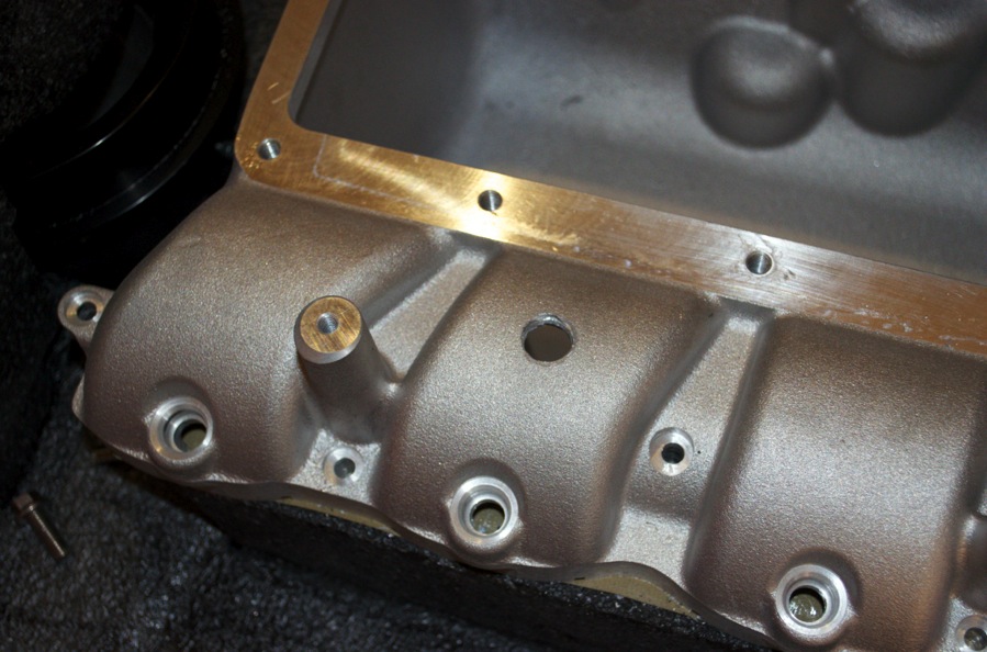
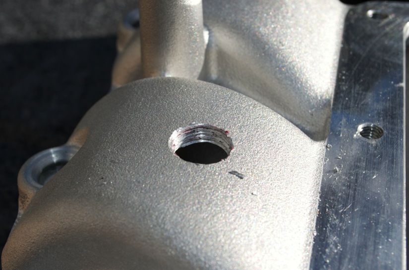
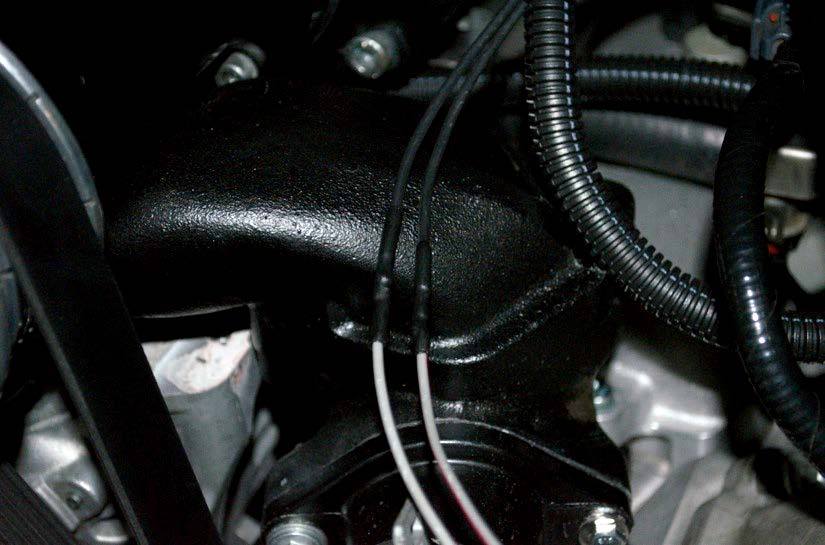
1. Choose a position to relocate your IAT sensor to. This is preferably a spot downstream of your power adder and downstream of any intercooling. Mark this spot and drill your hole using the 37/64-inch or 9/16-inch drill bit. I have chosen a runner in my Whipple supercharger manifold. Ensure that the spot where you drill into will have space for the sensor to stick out about an inch. If you are installing this on a Whipple, note how I have made my hole away from the fuel rail mount, because the sensor would not fit otherwise. The same reasoning goes for any location you choose to mount your IAT sensor to.
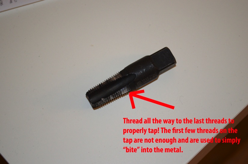
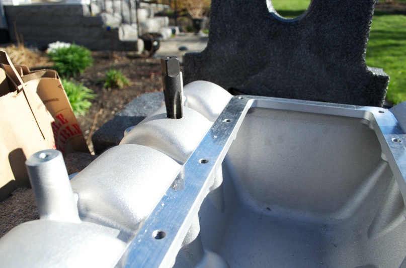
2. Use the 3/8-inch NPT tap. Insert it into the drilled hole and screw it into the hole. The tap will “bite” into the metal and create some resistance. Make sure you turn it slowly, using the adjustable wrench and applying some pressure downward on the bit to ensure that it threads correctly. You will notice that the tap is tapered; you need to screw it past the taper and into the main threads in order to create the 3/8-inch NPT threads properly (see below). Once tapped, CLEAN ALL SHAVINGS!
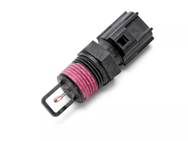
3. At this point, thread your sensor gently to test and make sure the threads work. There is a red thread locker on the sensor, it will give some resistance when you try to thread in the sensor. Just be gentle and thread past it. Clean up any residue left over on the threads (you will see it, it will be the red/pink paste).
4. Once you know the threads work, apply Teflon tape to your sensor. Refer to the picture below; you want to apply it to the upper half of the threads. Wrap the tape against the direction of the threads to ensure it does not “bunch up” when you install the sensor. One layer of tape is enough, do not double wrap.
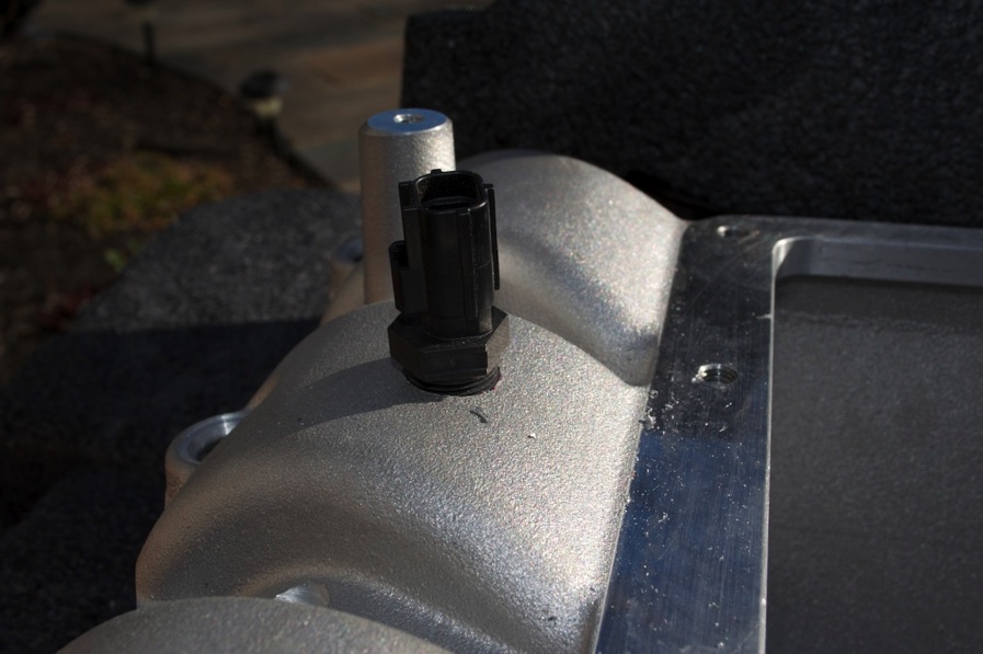
5. With the Teflon tape wrapped, thread the IAT sensor into the hole you made. Once it is hand tight, give it another 90 degree turn with your adjustable wrench. Be gentle as the sensor is plastic. Use your judgment and stop tightening if you feel a lot of resistance. The Teflon tape should do its job and create an airtight seal. (Note that this picture does not have the Teflon tape on but it should).
6. Now locate your MAF sensor. If you don’t know what it looks like, it is the sensor that is on your intake tube. The clip connector for it has a red tab and looks like this. It will have six (6) wires coming out of it. You can identify them as RED/YELLOW, BLACK/WHITE, TAN/BLUE, BLUE/RED, GREY/RED, and GREY. (The first color listed is the solid color of the wire and the second color is the color of the stripe on the wire).

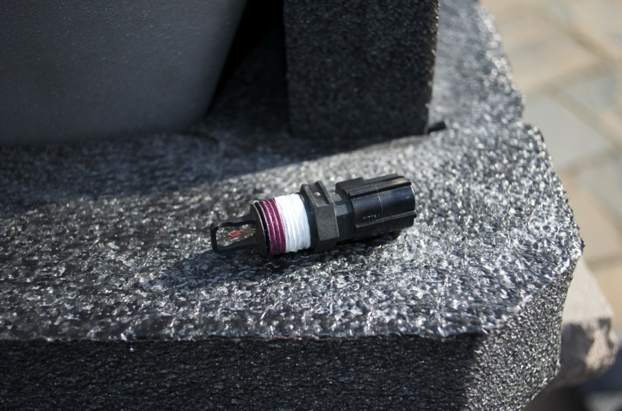
9. To wire the IAT, you need to splice into two of these wires and solder them to the two wires coming from the new sensor. Attach the connector that comes with IAT Relocation kit, it will clip onto the IAT sensor and have two black wires coming from it.
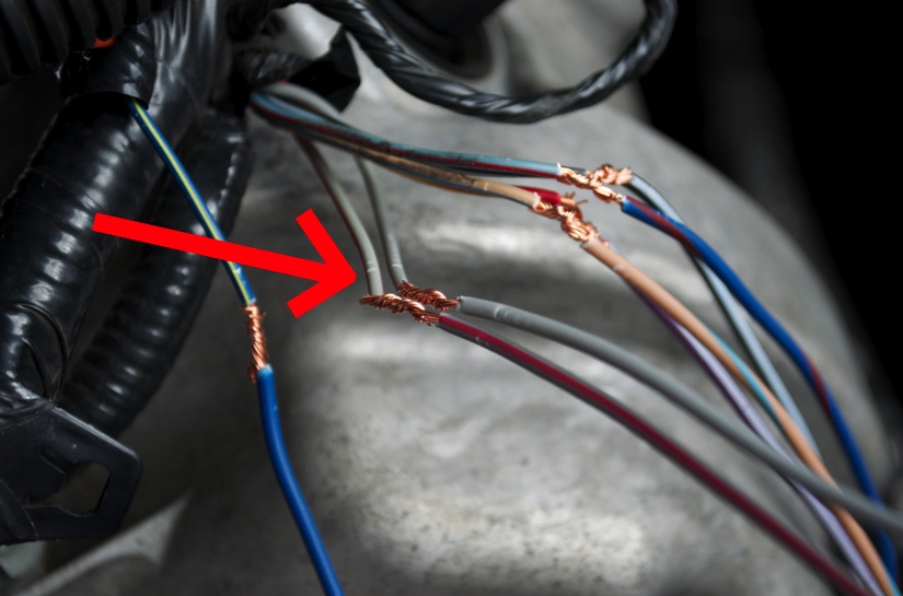
10. Cut the GREY/RED and GREY wires from the MAF. Make sure to leave about 2-3” of wire on the MAF side in case you ever need to solder the wires back together at a later date. These two wires are the signal wires for the IAT located on the MAF sensor. What we will do is take the two black wires and connect them to the GREY/RED and GREY wires we just cut. There are only two GREY wires on this sensor but if you are still confused, the two wires you want are in pins #1 and #2, which are all the way to one side of the sensor. In the picture above, note the orientation of the red tab (up). The two wires we want to cut are the two on the right of the picture.
11. Strip the ends of the two black wires from the IAT sensor and the GREY/RED and GREY wire. Ensure that you are connecting your IAT sensor to the harness side of the wires. This means, don’t solder your IAT sensor to the MAF sensor. You need to solder it to the wires that go into the loom (and eventually to your ECU).
12. See below for a close up of the GREY/RED and GREY wires. IGNORE the other wires in the pictures. They were used during a Whipple supercharger install. If you are installing a Whipple supercharger while doing this, it’s easy to do this step when you extend the MAF wires as per Whipple’s instructions.
11. Slip on the two pieces of heat shrink to each wire once you splice them together. Note that is does NOT matter which black wire goes to which GREY/RED or GREY wire. There is NO polarity to the IAT sensor. As long as one black wire goes to the GREY/RED and the other goes to the GREY wire, there is no problem. Solder the joint and apply the heat shrink. If the wires cannot reach, then you will need to extend the wires to your new IAT location. Again, the polarity does not matter.
12. Once this is done, you can use some wire loom or route the wires as you please, for aesthetics. As far as the sensor is concerned, you are finished and the IAT has been successfully relocated. Start your vehicle and ensure that there are no MIL codes. You can also use an aftermarket ECU tuning device to monitor the IAT from the new sensor to ensure its working. However, if you have no MIL codes, then the ECU is getting a proper signal for your relocated IAT sensor.
Installation Instructions written by AmericanMuscle customer Billy Zhang 4.27.12

