 FREE 1 to 3-Day Delivery on Orders $149+ Details
How to Install J&M Caster Camber Plates on your 1994-2004 Mustang

Shop Parts in this Guide
J&M CASTER/CAMBER PLATE INSTALLATION INSTRUCTIONS (#24213)
Thank you for purchasing J&M Product’s Caster/Camber Plates (#24213) for 1994-2004 Ford Mustang. The J&M Caster/Camber plates are the highest quality alignment plates on the market available for your Mustang. The J&M Caster/Camber plates allow the front suspension to have independent adjustment of caster and camber, which is desirable to improve front-end grip and steering response and also necessary on a lowered car to ensure proper tire wear.
Please read all instructions thoroughly before beginning installation and observe all safety procedures in the workshop. If you do not feel comfortable with the installation procedure, please contact your J&M Products retailer and ask them for a referral to a qualified shop. Once completed, be sure and have a qualified alignment shop align the vehicle to ensure maximum performance and proper tire wear.
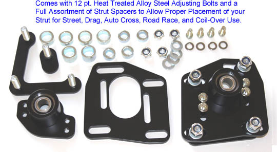
Contents:
2 - Camber Top Plates
2 - Caster plates/bearing Cups with Bearings
2 - Bottom Plates with 3 Threaded Studs
Hardware:
2 - M10 Stud Plates
8 - 5/16 Fine Thread Allen Bolts
8 - M10 Nylon Locking Nuts
8 - M10 F436 Heat Treated Washers
2 - 15mm Tall Strut Spacers
4 - 7.5mm Tall Strut Spacers
4 - 2.5mm Tall Strut Spacers
8 - Camber Plate Strut Tower Mounting Spacers
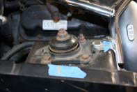
1. Before beginning disassembly, mark the position of the strut shaft relative to the strut tower. A couple of pieces of masking tape and a marker works well. This will ensure that once the J&M Caster/Camber plates are installed, you will be able to find a good alignment starting point.
2. Place the front end of the car on jack-stands and remove wheel. This will allow access to the strut mounting bolts. Place a floor jack under the front lower control arm such that it applies a small amount of lift on the lower control arm.
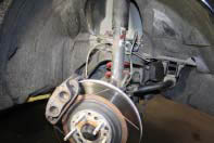
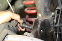
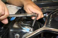
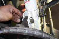
3. Many 94-04 Mustangs are equipped with ABS brakes. If your car has ABS brakes, begin by loosening and removing the ABS bracket mounting nut that attaches to the strut. If your car does not have ABS, you can skip this step.
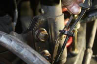
4. Loosen and remove both lower strut-to-spindle mounting bolts and nuts. The use of an impact gun is recommended, as these tend to be very tight. Slide out both strut-to-spindle mounting bolts. It may be necessary to slightly lower or raise the floor jack to allow the bolts to slide out.
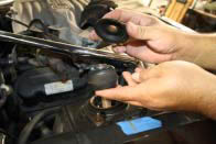
5. Loosen and remove the upper strut mounting nut. Do not use an impact gun. If you are re-using the same struts, you will need to re-use this nut that was just removed. If you are installing new or different front struts, a new nut may be supplied by the strut manufacturer.
6. With the upper strut mounting nut removed, the stock upper strut mounting components can be removed and discarded as they will not be used.
7. Now the strut is completely free and can be removed from the vehicle.
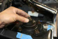
8. The three nuts that secure the top strut plate to the shock tower can now be removed and discarded as they will not be re-used. Often times, the top strut plate is also riveted onto the strut tower. If so, simply drill-out or chisel-off the rivet head to allow complete removal.
9. This is an “exploded view” of the factory strut along with the rubber bump-stop and dust boot. The bump-stop is the only thing that gets re-used.
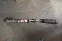
10. On this car, Tokico front struts are being installed in place of the original struts, making it necessary to remove the stock rubber bump-stop from the original strut and transferring it to the Tokico strut. If you are re-using your original struts, retain the bump-stop in its original location. The bump-stop is the only part that gets re-used.
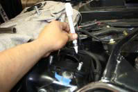
11. J&M Caster/Camber plates feature an optional fourth mounting bolt that can be installed if desired for maximum strength and durability. For light duty, streetdriving, it may not be necessary, but J&M always recommends taking a few extra minutes to do it now for best results. To do so, install the bottom 3 stud plate from under the strut tower with the threaded studs protruding through the factory holes/slots. Place main J&M Caster/Camber plate and place it over the studs on the strut tower and slide it and the lower stud plate all the way toward the fender (the most positive camber orientation.) The fourth hole can now be marked onto the strut tower again in the most positive camber orientation. This orientation allows you to use the camber plate slots along with the factory slots for the most non interrupted adjustability on the market. Once this is done, drilling can begin. Drill the fourth hole just large enough to allow the new supplied J&M bolt to pass through the newly drilled hole.
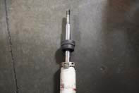
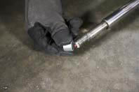
12. J&M supplies various strut spacers of different lengths to accommodate different ride heights. Most lowered Mustangs will require one “tall” strut spacer directly on the strut shaft itself as shown in the picture. The remaining strut spacers will be used at a later point. This combination will maximize suspension travel.
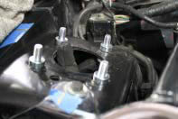
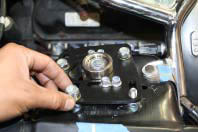
13. Once the optional fourth hole is drilled, the bottom plate can now be reinstalled from the bottom of the strut tower. Next, slide the J&M supplied caster/camber plate spacers over the threaded studs protruding from the strut tower.
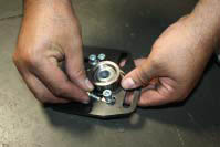
14. Assemble the bearing cup onto the caster/camber plate as shown with the supplied J&M bolts and washers. Leave bolts loose for now to allow for easy adjustments.
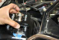
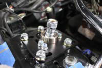
15. The complete caster/camber plate and bearing cup assembly can now be installed over the protruding studs and spacers on the strut tower.
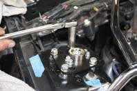
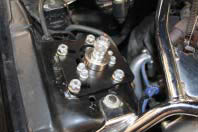
16. Loosely secure the caster/camber plate and bearing cup assembly with the J&M supplied washers and lock nuts. Leave loose to allow for adjustment.
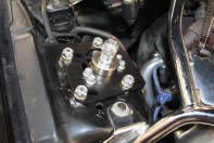
17. Position the caster/camber plate and bearing cup assembly such that the strut will align with the marks you made on the masking tape in step 1. Now all the caster/camber plate and bearing cup assembly bolts can be tightened.
18. The strut can now be installed through the bearing cup in the caster/camber plate assembly. At this point, the remaining strut spacers can be installed on the threaded shaft of the strut. In our case, we used 2 “medium” length strut spacers and 2 “short” spacers per side on the top-side of the strut. Lastly, the top strut nut can be installed. Leave this loose for now.
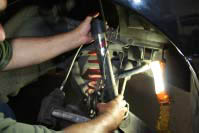
19. The original strut-to-spindle bolts and nuts can now be re-installed and torque to spec. Don’t forget to secure the ABS bracket and line, if your Mustang is equipped with ABS.
20. At this point, the top strut nut can be tightened to the strut manufacturer’s specification (DO NOT USE AN IMPACT GUN.) Go back and double check that all mounting hardware is tight. Double check your preliminary alignment settings.
20. Repeat the procedure for the driver’s side.
Congratulations: You have just finished installation of the strongest most advanced camber plate on the market. These are a few features that set our plates apart from the rest.
• Widest range of un-interrupted camber adjustment in the industry: Our plates not only have longer slots for camber but also allows the use of the factory slots giving you greater adjustment compared to other 4 bolt camber plates.
• Lifetime guarantee on the Made in the USA super high strength PTFE lined spherical bearing.
• Plates are spaced above the strut tower to gain bump travel on lowered cars.
• Our bearing is placed underneath the main plate for increased strength compared to other plates that place the bearing above the main support plate. By placing the bearing mount under it spreads the load throughout the main plate and not just through the small foot-print of the nuts.
• Alloy steel is used for our main plate making them super strong and thinner compared to aluminum.
• Lifetime warranty on the entire camber plate against bending. (must use with the 4 bolt option.)
IMPORTANT: OUR BEARINGS ARE SWAGED TO A F2 FIT WITH A PTFE LINER. THIS WILL MAKE THEM HARD TO MOVE AND THIS IS PERFECTLY NORMAL. DO NOT USE ANY LUBRICANT ON THE BEARINGS AS THIS WILL ATTRACT DIRT AND POSSIBLY DAMAGE THE PTFE LINER VOIDING YOUR WARRANTY.
