 FREE 1 to 3-Day Delivery on Orders $149+ Details
How to Install JMS PowerMAX V2 FuelMAX Fuel Pump Voltage Booster (05-10 GT, V6) on your Ford Mustang
Installation Time
90 minutes
Tools Required
- 10mm Socket
- 1⁄4” Socket
- Impact Drill
- Ratchet
- Side Cutters
- Additional Zip Ties (Optional)
- Flat Head Screwdriver
- Lug Wrench
- Floor Jack
- Jack Stand
- Wheel Chocks or Bricks

Shop Parts in this Guide
Note: The PowerMax unit has been designed to be mounted inside the vehicle cabin or in the trunk. Install the unit so it does not come into direct or prolonged exposure to water or extreme engine heat ( 250°F). Cable routing and wire connections will vary upon unit placement and activation settings. Refer to Figure P for activation settings.
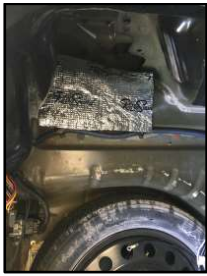
Figure A: Before Installation Picture
1. Verify the vehicle is turned off (no key in ignition).
2. Utilize wheel chocks or bricks to secure the rear wheels.
3. Raise the vehicle (front driver side only) in accordance with your owner’s manual.
4. Remove the front driver side wheel in accordance with your owner’s manual.
5. Remove the front driver side wheel well cover, rear only. (Figure B)
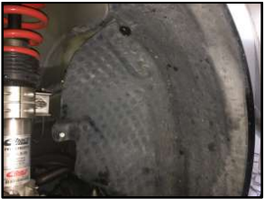
Figure B: Wheel Well Cover
Note: Steps 2 through 5 are only necessary if installing a Hobbs switch in the engine compartment.
6. Remove the plastic cover in the rear of the trunk. (Figure C)
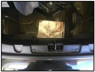
Figure C: Rear Trunk Plastic Cover
7. Remove the driver side trunk side wall carpeting. Note: This step is optional depending upon unit placement and wire harness routing.
8. Remove the spare tire.
9. Locate the fuel pump driver module. (Figure D). Fuel pump driver module is located to the rear and left of the spare.
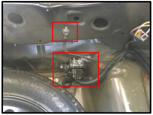
Figure D: Fuel Pump Driver Module and Factory Point Ground Wire (Spare tire left in for orientation)
10. Disconnect the factory harness and the fuel pump driver module. Press and hold the tab to remove the connector plug.
11. Install the JMS plug & play fuel pump driver module harness in-between the factory harness and the fuel pump driver module. (Figure E)
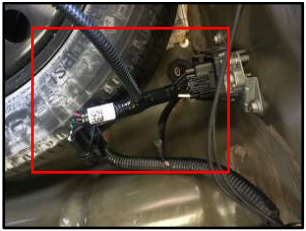
Figure E – JMS Plug & Play Fuel Pump Driver Module Harness (Spare tire left in for orientation)
12. Connect the two pin connector to the PowerMax.
13. Utilize the 10mm socket and ratchet to secure the ground wire to the factory point. It is located in the rear of the trunk, above the fuel pump driver module.(Figure D)
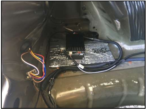
14. Mount the PowerMax unit. (Figure E) Utilize the self-tapping screws, 1⁄4” socket and impact drill to mount the PowerMax unit.
Note:
- Ensure unit switches and knobs can be easily seen and accessed.
- Avoid drilling the self-tapping screws into factory fuel lines, brake lines and wire harnesses.
- Mount the unit away from extreme hear and direct contact with water. Unit can be mounted in vehicle cabin or trunk.
- Ensure mounting location provides enough slack in the PowerMax harnesses to avoid strain on the connections.

Figure E: PowerMax Unit Mounting Location
Note:
- Control cable routing will vary upon unit placement and activation settings. Refer to Figure P for different activation settings.
- These instructions will outline the procedures for installing the Hobbs switch (Provided by JMS) from a boost source.
- Control cable is routed from the trunk, though vehicle cabin (driver side) and into the engine compartment.
a. Remove the rear seat, drive side door sill and kick paneling located near the pedals.
b. Lift the carpeting to expose the factory harness near the driver’s seat.
c. Route the control cable by following the factory harness from the trunk into the vehicle cabin.
d. Continue to follow the factory harness from the rear seat, left of the driver’s seat up to the firewall under the dashboard, left of the pedals.
e. Route the control cable into the engine compartment. (Figures J and K)
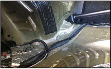
Figure F: Cable Routing from Trunk into Vehicle Cabin
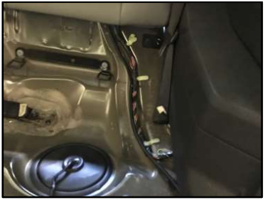
Figure G: Cable Routing in Rear Seat
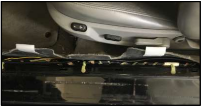
Figure H: Cable Routing Left of Driver’s Seat
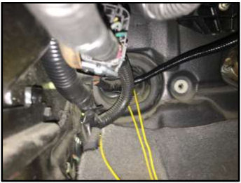
Figure I: Cable Routing Underneath Dashboard
Optional: Utilize zip ties when routing along factory harness.
a. Access point located in the firewall, within the drive’s side wheel well.
b. Left of the factory harness, cut a hole in the rubber seal.
c. Push the control cable through the rubber seal.
d. Follow the factory harness up into the engine compartment.
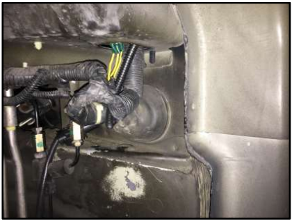
Figure J: Cable Routing through Engine Firewall and Up Into Engine Compartment
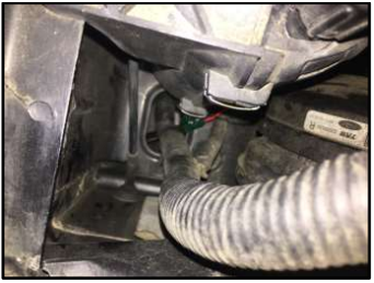
Figure K: Cable Routing Into Engine Compartment (Looking Down)
16. Install Hobbs Switch. (Figure L, M and N)
a. Connect to boost source.
i. Cut boost source tube.
ii. Install T-Fitting between factory tubing.
iii. Install tubing (Provided by JMS) from T-Fitting to Hobbs switch.
b. Connect Hobbs switch to control cable.
i. Connect the control cable Grey wire to one side of the Hobbs switch.
ii. Connect the control cable Black wire to the other side of the Hobbs switch.
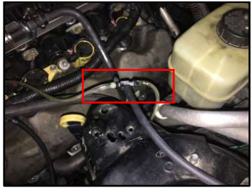
Figure L: Boost Source T-Fitting
Note: There are multiple options for boost source. Fuel Rail Sensor or Intake Manifold Accessory Port(s). These instructions utilize Intake Manifold Accessory Port. You can utilize the appropriate sized T-Fitting for boost source. JMS provides (3) T-Fitting sizes.
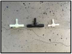
Figure M: JMS Provided T-Fittings
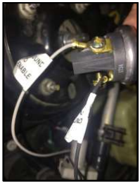
Figure N: Hobbs Switch Control Cable
17. Upgrade the Fuel Pump Fuse. (Figure O)
a. Refer to your owner’s manual for the location of the Fuel Pump fuse.
b. Remove the fuse box cover.
c. Remove the stock fuse.
d. Install JMS provided fuse
e. Replace the fuse box cover.
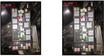
Figure O: Fuel Pump Fuse Replacement
18. Verify PowerMax unit powers on. Green LED will illuminate ON (solid) when the ignition key is set in the ON position.
19. Adjust the Boost Voltage and Range.
a. Turn the ignition key to ON (Power ON = PowerMax Green LED is ON)
b. Set Dip Switch 1 – ON. Switch 1 ON enables the configuration of the front panel switches and knobs).
c. Change Switches 2-5, adjust input trigger and output voltage in accordance with Figure P.
d. Set Dip Switch 1 – OFF. Front panel switches and voltage settings are saved. Green LED twinkles.
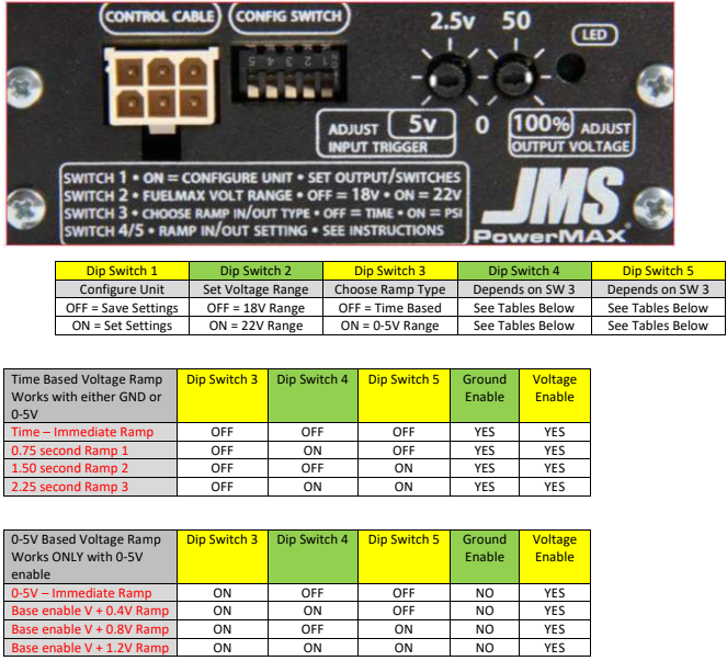
Figure P: PowerMax Front Control Panel Activation Settings
20. Start the Engine to ensure the PowerMax unit turns on and the engine starts.
21. Install the wheel well cover.
22. Install the driver side front wheel.
23. Safely remove the jack stand and lower the vehicle.
24. Remove the wheel chocks or bricks.
After Installation
Installation Instructions provided by AmericanMuscle Customer
