 FREE 1 to 3-Day Delivery on Orders $149+ Details
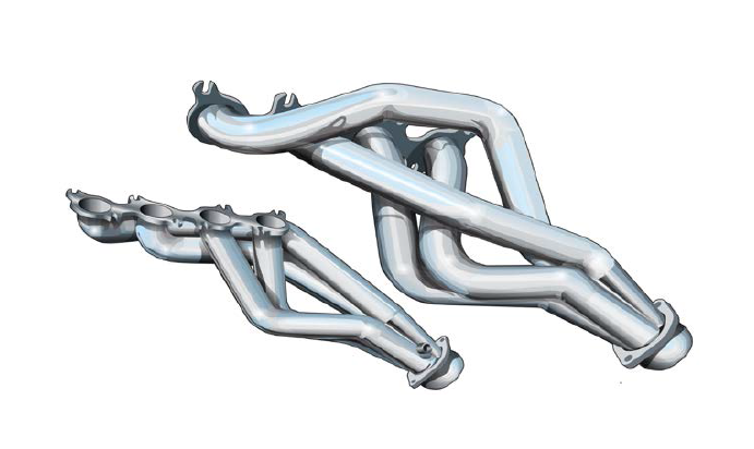
How to Install a Kooks Super Street Shorty Headers 1-7/8in on your 2011-2014 Mustang GT and Boss 302
Installation Time
1 days
Tools Required
- Vehicle Lift (Jack and 4 Jack Stands)
- Engine Cradle
- Ratchet Set (1/4” & 3/8” Drive)
- Metric Socket Set (1/4” & 3/8” Drive)
- Extensions (1/4” & 3/8” Drive)
- Pry Bar Set
- 7/8” O2 Socket (7/8” Wrench)
- Gasket Scraper
- Metric Wrench Set (Ratchet Wrenches)
- Standard Screwdriver Set
- Safety Glasses
- Paint Pen (Marker)
- Service Manual
- Thread Locker
- Anti-seize

Shop Parts in this Guide
Do not attempt this installation if proper safety equipment isn’t available to you.
Seek the assistance of a professional installer.
Kooks Mustang headers install from beneath the vehicle.
Raising and securing the vehicle is a must.
Read and understand all instructions before beginning.
VEHICLE PREPARATION
**Raise and Support Vehicle (Refer to Owner’s Manual for specified jacking points)**
*Always disconnect the negative battery terminal before performing this type of work on any vehicle*
STOCK MANIFOLD AND CATALYTIC CONVERTER REMOVAL PROCESS
To aid in the overall speed of disassembly, the following steps will be performed from the topside of the Engine Compartment before moving to the underside.
STEP 1. Battery and Battery Tray
• Disconnect the negative and positive battery terminal.
• Remove the battery tie down strap and remove the battery.
• Remove the three 6mm bolts in the Battery Tray and remove the Battery Tray.
STEP 2. Air Box
• Disconnect the Mass Airflow Sensor.
• Remove the Air Intake Hose.
• Unclip the top half of the Air Box and remove the Filter Element.
• One 10mm bolt holds the lower half of the air box in. Remove this bolt and pull upward on the air box to release it.
STEP 3. Steering Shaft
• Assure steering is locked.
•Mark the relationship of the Upper Steering Knuckle to the Steering shaft.
• Remove the 13mm bolt from the Upper Knuckle of the Steering Shaft (the lower Steering Shaft Knuckle Bolt can be removed at a later time).
STEP 4. Engine Mount (Drivers Side and Passenger Side)
• Remove the 15mm Engine Mount Nut.
• Remove the two 13mm Bolts on either side of Engine Mount.
*NOTE – Do NOT excessively rock the Engine after removing Engine Mount Hardware*
STEP 5. Exhaust Manifolds
• Remove all 15mm Exhaust Manifold Nuts visible from above the engine compartment.
• Remove Passenger Side Catalytic Converter Outer Nut (visible from above engine compartment sighting down Passenger Frame Rail).
Remaining Exhaust Manifold Hardware can be removed at a later time.
The remaining removal steps will be from beneath the Vehicle.
STEP 6. Oil Filter Access Panel
• Remove the three 8mm Oil Filter Access Panel Bolts.
• Hinge panel down (it is not necessary to completely remove the Access Panel).
STEP 7. Subframe Support Brace (Located beneath Bell Housing)
• Remove the four 15mm Lock Nuts.
• Remove Support Brace.
STEP 8. Starter
• Disconnect Starter Wires.
• 13mm nut on the Positive Wire.
• 10mm nut on the Jumper Wire.
**Note the location of each wire**
• Remove the three 10mm Bolts from Starter.
• Remove Starter.
STEP 9. O2 Sensors
• Note the position of each O2 Sensor.
• Disconnect all four O2 Sensors from Wiring Harness.
• Remove front two O2 Sensors (7/8” Wrench or O2 Socket).
**If installing Kooks Long Tube Headers remove Rear O2 Sensors**
STEP 10. Factory Catalytic Converter and H-Pipe
• Support the Factory H-Pipe and Catalytic Converters.
• Remove remaining three 15mm Catalytic Converter Nuts.
*Note - Passenger side outer Catalytic Converter nut was removed in Step 5.
• Loosen 2 ¾” x 3 ½” – 2 Bolt Clamp.
(Clamp connecting Factory H-Pipe to Factory Mid Pipes)
*Note – This clamp is to be reused on all Kooks Exhaust Systems.
• Remove H-Pipe and Catalytic Converters as one unit.
STEP 11. Steering Shaft
•Mark the relationship of the Lower Steering Knuckle to the Rack and Pinion Input Shaft.
• Remove the 13mm bolt from the Lower Knuckle of the Steering Shaft.
• Remove Steering Shaft (Steering Column retracts into Firewall allowing for the removal of the Steering Shaft).
STEP 12. Engine
• Kooks recommend the use of an Engine Cradle for safety and ease of installation.
• Raise Engine approximately 1½”.
**DO NOT SUPPORT ENGINE ON OIL PAN**
STEP 13. Engine Mount Bracket (Drivers Side and Passenger Side)
• Remove hardware attached to Engine Mount Bracket.
• 13mm Nut.
• Remove four 13mm Bolts attaching Engine Mount Bracket to Engine.
• Remove Engine Mount Bracket.
STEP 14. Exhaust Manifold (Drivers Side and Passenger Side)
• Remove remaining 15mm Exhaust Manifold Nuts.
• Remove Exhaust Manifold.
• Remove all Exhaust Manifold Studs.
Exhaust Manifold Studs will be replaced with the supplied Kooks hardware.
Kooks supplies two sets of replacement hardware, compare factory studs to Kooks hardware to ensure the correct bolts are used during the installation.
STEP 15. Cylinder Head (Drivers Side and Passenger Side)
• Clean Cylinder Head.
Kooks Header and Connection Pipe Installation Process
**All hardware should be tightened to factory specifications**
STEP 1. Kooks Header (Drivers Side and Passenger Side)
• Align supplied gasket and start two of the four Lower Header Bolts.
**Note Correct Hardware**
• Align Header on Lower Header Bolts and start remaining Header Bolts.
• Lower Engine (enough to allow for tightening of Header without Header interfering with vehicle floor).
• Tighten Headers to Factory Exhaust Manifold Torque Specs using Factory Torque Spec Sequence.
STEP 2. Engine Mount Bracket (Drivers Side and Passenger Side)
• Apply Thread Locker to Engine Mount Bracket Hardware.
• Align Engine Mount Bracket and start four Engine Mount Bolts.
• Tighten Engine Mount Bracket.
• Reinstall Hardware originally attached to Engine Mount Bracket.
STEP 3. Engine Mount (Drivers Side and Passenger Side)
• Apply Thread Locker to Engine Mount Hardware.
• Start two 13mm Bolts originally removed from either side of Engine Mount.
• Lower Engine onto Engine Mounts.
• Center Engine in Vehicle.
• Tighten all Engine Mount Hardware.
STEP 4. Starter
• Align Starter and start three Starter Bolts.
• Tighten Starter Bolts.
• Install Starter Wires noting original location of each. **Do Not over tighten**
• Wrap Starter Wires with Supplied Heat Tape.
STEP 5. Steering Shaft
• Note the original orientation of Steering Shaft.
• Align Steering Shaft with previously made marks (Installs through Header).
• Apply Thread locker to Steering Shaft Bolts.
• Install Steering Shaft Bolts and tighten.
STEP 6. Oil Filter Access Panel
• Align Oil Filter Access Panel and start three Access Panel Bolts.
• Tighten Access Panel Bolts to Specs listen on Access Panel.
STEP 7. Subframe Support Brace
• Align Subframe Support Brace.
• Tighten four 15mm Lock Nuts.
STEP 8.
Kooks Long Tube Headers
Kooks Connection and H / X-Pipe
• Align Kooks Connection and H / X-Pipes with Kooks Headers and Mid Pipes.
• Support Exhaust System in correct location.
• Install all hardware and tighten front to rear.
• Use supplied Hardware and Factory 2 ¾” x 3 ½” – 2 Bolt Clamp.
Kooks Shorty Headers
Factory Catalytic Converter and H-Pipe
• Align Factory Catalytic Converter and H-Pipe.
• Install all Factory Hardware and Tighten.
STEP 9. O2 Sensors
• Apply Anti Seize to the threads of all O2 Sensors.
• Install O2 Sensors noting their original location.
• Install supplied O2 Extensions where needed.
STEP 10. Air Box
• Align Lower Air Box and tighten Bolt.
• Install Filter Element and reinstall Air Box Lid.
• Align Air Intake Hose and tighten.
STEP 11. Battery and Battery Tray
• Align the Battery Tray and tighten Bolts.
• Replace the Battery and Battery Hold Down Strap.
• Connect the Positive Battery Cable.
• Assure all steps have been completed and connect the negative Battery Cable.
STEP 12. Inspection
• Start Engine and check for any Exhaust Leaks.
• Allow Vehicle to complete one heat cycle (Heat to temp and allow for cooling).
• Re-torque Header Bolts and Header Hardware.

