 FREE 1 to 3-Day Delivery on Orders $149+ Details
How To Install a Lakewood Driveshaft Safety Loop on your 2005-2014 Mustang

Shop Parts in this Guide
LAKEWOOD DRIVE SHAFT SAFETY LOOP #18005 INSTALLATION INSTRUCTIONS
Fits: 2005-2006 FORD MUSTANGS
The Lakewood Drive Shaft Safety Loop is made from 1/4" thick steel and is 2" wide which complies with specifications stated in the NHRA & IHRA rule books. This safety loop is designed to fit near the transmission tail shaft in the tunnel area.
CAUTION: DO NOT BEGIN THIS INSTALLATION UNTIL YOU ARE CONFIDENT THAT VEHICLE IS SECURE AND SAFELY SUPPORTED.
WORK SAFELY!
Installation of this Drive Shaft Safety Loop requires working inside and underneath the
vehicle USE EXTREME CARE AND CAUTION WHEN WORKING UNDERNEATH ANY VEHICLE. Never get near or under vehicle until you are confident that it is safely supported and will not move or fall from its raised position. DO NOT USE A BUMPER JACK.
PREPARATION FOR INSTALLATION
1. Place vehicle on solid level surface such as a garage floor to ensure safe installation.
2. Place wheel blocks or wedges in front of and behind both rear wheels to prevent movement in either direction.
3. Carefully place floor jack under front engine cross member. Be careful not to damage rack and pinion unit.
4. Raise front of vehicle up with floor jack and place automotive approved support stands having adequate load capacity under lower control arms.
5. Lower floor jack until control arms are resting securely on the support stands.
Figure A
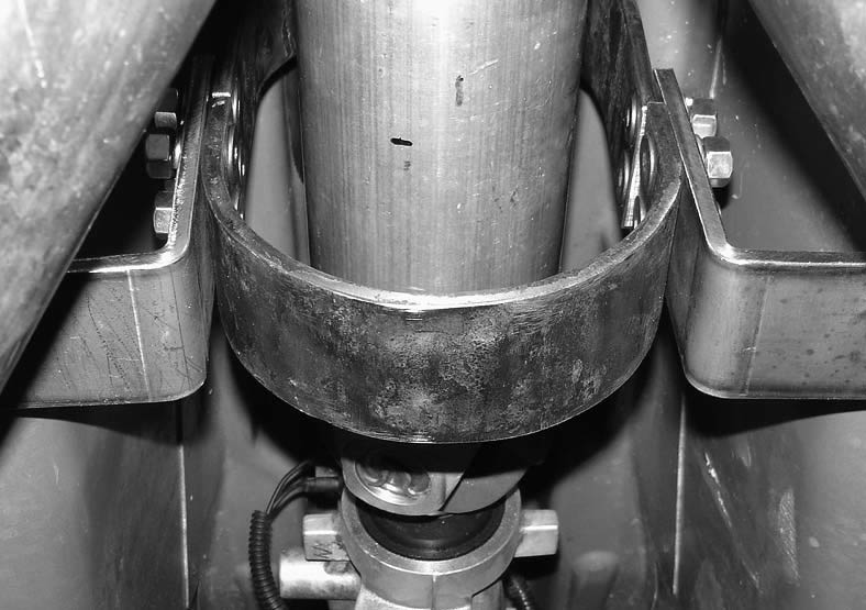
DRIVE SHAFT SAFETY LOOP INSTALLATION
1. Assemble the safety loop “loosely” around Drive Shaft, about 6-8 inches away from the Transmission Tail shaft. (See Figure A)
2. Next, remove the lightweight aluminum heat shields for installation. (Please note, these can be re-attached after loop installation, if needed.)
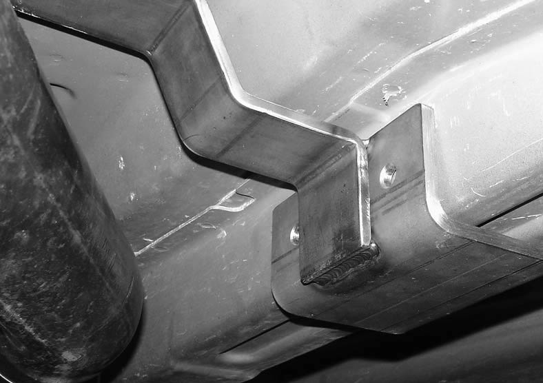
3. Next, position the outer loop frame brackets, on both sides, around the frame rail sections where the loop will be mounted. (See Figure B)
Figure B
4. Then, finger tight all nuts and bolts stiffening up the assembly so you can test mount the safety loop prior to permanent installation.
5. Once you have tested where the loop needs to be mounted, make sure you have proper clearance around drive shaft and exhaust. (See Figure A)
6. Now that the safety loop is in the desired location, mark the bracket holes on the frame and then drill holes with 3/8” drill bit for attaching the outer frame brackets. (See Figure B)
7. Next, install bolts through frame mounting brackets and through the drilled frame holes mounting the safety loop in place.
Figure C
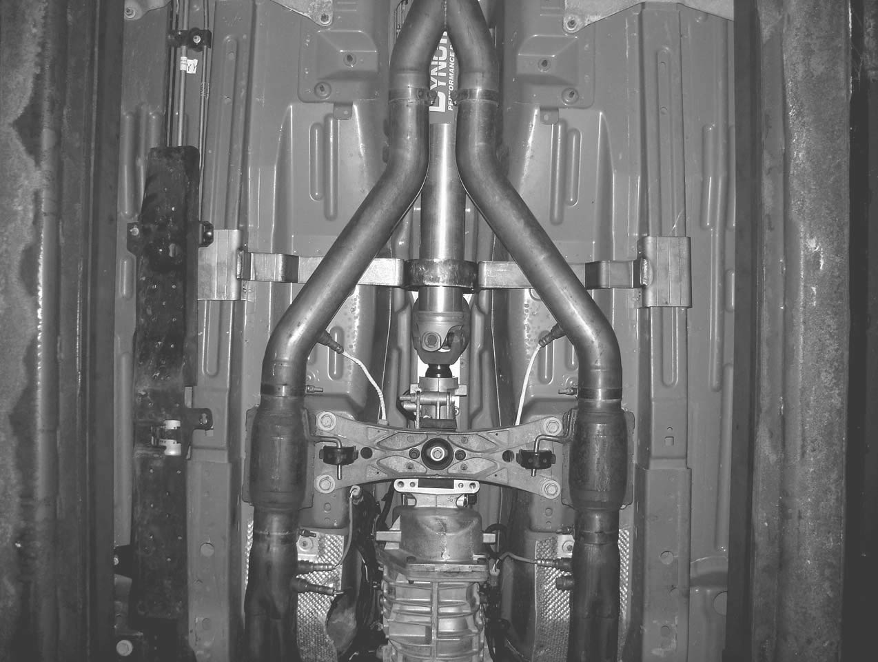
8. For correct placement of the drive shaft safety loop. (See Figure C)
9. Be sure to tighten and torque down all fasteners after correct installation has been completed.
TECHNICAL SERVICE
A highly trained technical service department is maintained by Lakewood Industries to answer your technical questions, provide additional product information and offer various recommendations. See your local retailer of Lakewood products for specific prices. Technical service calls, correspondence and warranty questions should be directed to the following address:
Lakewood Industries
10601 Memphis Ave. #12
Cleveland, Ohio 44144
Phone 216-688-8300 ext. 500
8:30 A.M.-12:00 P.M., 1:00 P.M.-5:00 P.M. EST
www.lakewood-industries.com
RETAIN THIS INSTRUCTION SHEET FOR FUTURE REFERENCE.

