FREE 1 to 3-Day Delivery on Orders $149+ Details
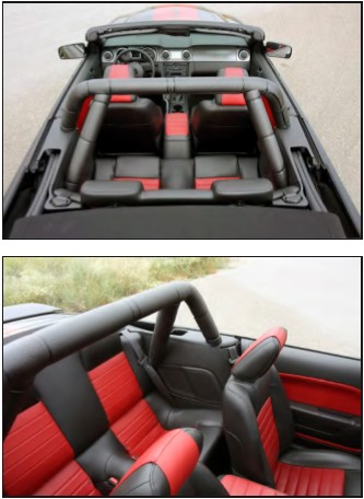
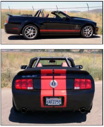
How to Install Maximum Motorsports 4-Point Street Roll Bar (05-14 Convertible) on your Ford Mustang
Installation Time
4 hours
Tools Required
- T-47 Torx Bit
- Standard assortment of hand tools
- 6mm socket
- 8mm socket or wrench
- 13mm wrench and socket
- 15mm wrench and socket
- 9/16” wrench and socket
- Torque wrench
- Drill
- 1/8” pilot drill
- 7/16” drill bit (more than one may be useful)
- Floor jack
- 2 jack stands
- Straight-edge or long ruler
- Hacksaw or Wood Saw
- MIG or TIG Welder
- Center punch
- 1-3/4” hole saw

Shop Parts in this Guide
Read all instructions before beginning work. Following instructions in the proper sequence will ensure the best and easiest installation.
The latest-version, high-quality COLOR instructions are available online at www.maximummotorsports.com. Check the bottom of your installation instructions for the date and compare it to the copy available online.
Do you want to die? If not, pay attention to this:
The rear braces must be welded to the main hoop. That step is not optional. The rear spuds are not structural; they are there only to align the rear braces to the main hoop for easy welding. If the rear braces are not welded to the hoop and the car rolls over, you will probably be killed because the spuds will break off the hoop and allow the roll bar to collapse. Follow the instructions and properly weld the rear braces to the main hoop. Check the MM Facebook page and website for a graphic example of how good the MM roll bars are when properly installed.
With MM’s innovative design, the rear braces bolt to the main hoop, which holds them in the correct position so they can be welded while outside of the car. This unique design reduces shipping charges, and saves you the time and effort of stripping the interior of your car to protect it from welding sparks.
NOTE: Due to the required welding for installation, the MM roll bars are shipped uncoated. For best results, complete the installation, then remove the roll bar for either painting or powdercoating, and then reinstall. That way you will avoid wear and tear on your finish while drilling holes.
Preparation
• The vehicle must be safely supported on jack stands and have the rear wheels removed. For roll bars with the door bar option, the entire vehicle must be supported on jack stands to gain access to the plastic panel covering the fuel filter.
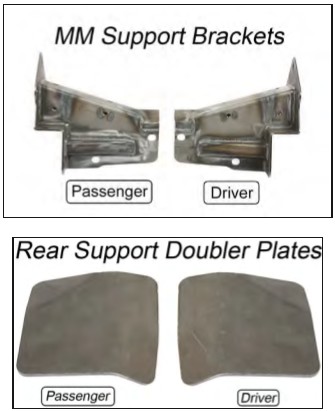
• The MM support brackets are shipped unpainted. We recommend painting the brackets prior to the actual installation so they don’t have to be removed once correctly positioned.
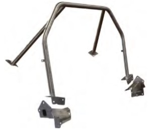
• Unpack the roll bar and remove the supplied hardware and mounting plates/brackets. Verify that the items in the hardware list below are present.
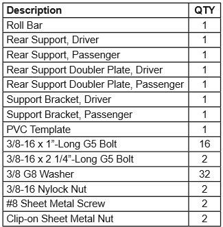
This kit contains:
Interior Removal/Preparation
1. Lower the convertible top.
2. Slide the front seats forward.
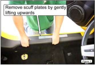
3. Remove the door sill scuff plates. Pull up at the ends and middle of the plates to disengage the snap-in retainers (Figure 1).
NOTE: Some vehicles have an electrical plug attached to the scuff plates that must be disconnected before removal.
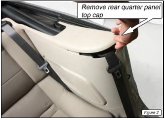
4. Remove the rear quarter panel top caps by gently pulling upward until the retaining clips disengage (Figure 2).
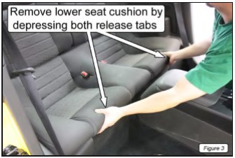
5. Remove the rear seat cushion. Push rearward on the two seat cushion release tabs while lifting up at the front to remove the rear cushion assembly (Figure 3).
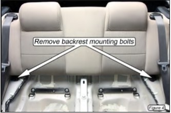
6. Using a 13mm socket, unscrew the hex bolt on the lower, outboard corners of the rear seat backrest (Figure 4).
7. Gently unclip the convertible top from the backrest and remove the backrest by lifting it vertically.
NOTE: It may be helpful to use a small screwdriver to unclip one side of the top. Once begun, the remainder of the top should easily unclip.
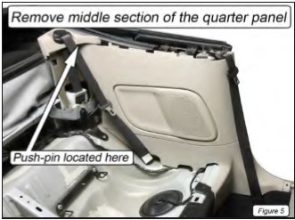
8. Remove the middle section of the rear quarter panels. There is one push-pin retainer at the upper, rearmost point of the panel. Raise the top part-way to gain access to the pin (Figure 5).
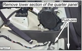
9. Remove the lower section of the rear quarter panels. There are two push-pin retainers on each panel; one is located at the front of the seat bulkhead and the other atop the bulkhead, adjacent to the seat belt retractor (Figure 6).
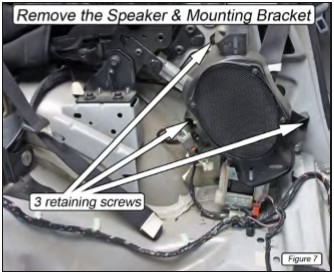
10. Remove the speakers along with their mounting brackets. Be sure to disconnect any attached wiring harness and the plastic seatbelt guide (Figure 7).
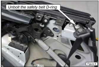
11. Unbolt the safety belt D-ring from the top of the B-pillars (Figure 8).
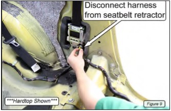
12. Disconnect the harness where it plugs into the seatbelt retractors (Figure 9).
NOTE: There is a release clip that must be disengaged on the inboard face of the seatbelt retractor electrical connector on most vehicles. Use a small screwdriver to pop the release clip up, away from the connector.
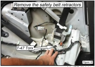
13. Remove the T-47 Torx bolts holding the safety belt retractors to the B-pillars (Figure 10).
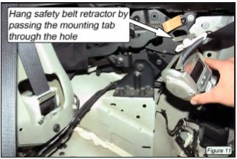
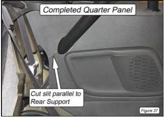
14. Temporarily hang the retractors by passing the mounting tab through the hole in the convertible top pivot assembly (Figure 11).
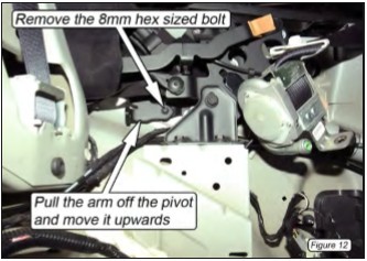
15. Remove the 8mm bolts, directly rearward of the main pivots of the convertible top. Pull the pivot arms off the pivots and push them upward ~1/4” (Figure 12).
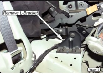
16. Unbolt the convertible top main pivot support L-brackets and remove (Figure 13).
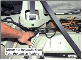
17. Unclip both pairs of the hydraulic cylinder actuator lines from the plastic retaining clips located below the rear passenger safety belt retractors (Figure 14).
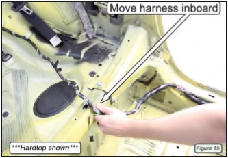
18. Pull the harnesses inboard to clear the factory support brackets. Unclip any retainers as necessary (Figure 15).
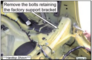
19. Unbolt and remove the two factory support brackets that connect the B-pillar to the rear seat bulkhead. Each bracket has seven 13mm hex head-sized bolts and two 15mm hex head-sized bolts (Figure 16).
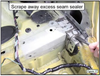
20. Scrape away any excess seam sealer around the factory support bracket mounting areas (Figure 17).
MM Support Bracket Installation
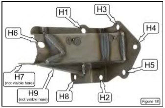
There will be gaps due to vehicle production tolerances between the MM support bracket and the vehicle. These gaps must be minimized to 1/8” or less around the B-pillar mounting holes. We provided extra washers for this task. Use the following steps to position the driver- and passenger-side brackets correctly. Below is a picture identifying the individual holes (Figure 18).
21. Starting on the driver side, set the MM support bracket into position. It should be resting against the B-pillar and the front of the rear seat bulkhead.
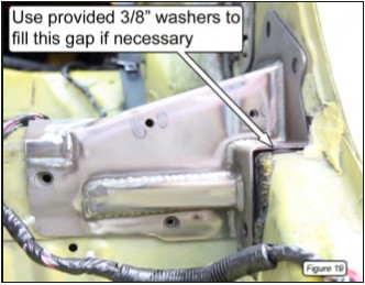
22. Check the gap between the bracket and the vehicle at Hole 2 (H2). Use the provided 3/8” G8 washers to close the gap to 1/8” or less. Then insert one of the factory mounting bolts into the hole to prevent the washers from being dislodged (Figure 19).
NOTE: Small gaps are acceptable, as the vehicle and the MM support bracket will conform to each other as the mounting bolts are tightened.
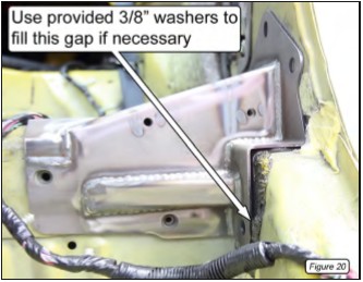
23. Check the gap between the bracket and the vehicle at H8. Use the provided 3/8” G8 washers to close the gap to 1/8” or less. Then insert one of the factory mounting bolts into the hole to prevent the washers from being dislodged (Figure 20).
NOTE: It may be helpful to tape the washers to the end of a small screwdriver to aid in sliding them into position.
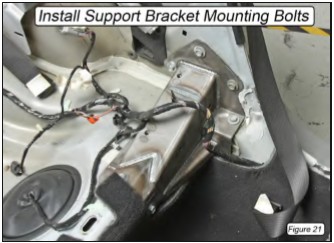
24. Install the remaining mounting bolts into the support bracket and tighten them by hand. Take note that H6 and H7 use the larger, 15mm hex head bolts (Figure 21).
25. Using a wrench, tighten (but do not torque) all of the bolts in numerical order from H1 to H9 so the bracket can be properly seated against the vehicle.
26. Following the same numerical order, torque the 13mm hex-size bolts to 17lb-ft (23Nm) and the 15mm hex-size bolts to 48lb-ft (65Nm).
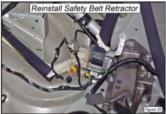
27. Reinstall the safety belt retractor and torque the T-47 Torx bolt to 30 lb-ft (Figure 22).
28. Repeat Steps 21-27 for the passenger-side bracket.
Main Hoop Installation
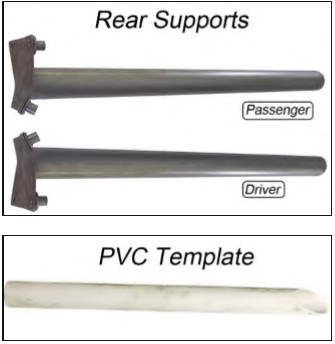
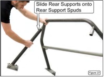
29. Slide the driver- and passenger-side rear supports onto the rear support spuds and secure them with the provided 3/8” x 2 ¼”-long bolts and 3/8” Nylock nuts. Only hand tighten; do NOT torque them yet (Figure 23).
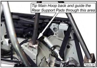
30. With the help of another person, position the roll bar in front of the B-pillars so the rear supports are above the MM support brackets and at the same height as L-Brackets removed in Step 16. Slide the hoop rearward while tilting it back so the rear support mounting pads pass directly over the L-Bracket mounting areas. Once the pads clear the L-Bracket mounting areas, the hoop can be tilted forward and the main hoop mounting pads placed on the MM support brackets. The rear support mounting pads should rest flat against the rear fender wells (Figure 24).
NOTE: Take care not to crush or puncture any hydraulic or electrical wires while setting the roll bar in position.
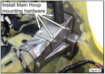
31. Loosely secure the hoop to the MM support brackets using the provided 3/8” G8 washers and 3/8”-16 x 1” G5 bolts (Figure 25).
NOTE: In some cases, it may be necessary to enlarge the holes in the main hoop mounting pads to provide clearance for the mounting bolts.
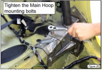
32. Temporarily tighten the bolts that secure the hoop to the MM support brackets (Figure 26).
33. With both rear support mounting pads in their proper position (resting firmly against each rear wheel well), tighten the two bolts holding the rear supports to the main hoop so the rear supports CANNOT move.
34. Mark the position of the four mounting holes in each rear support mounting pad onto the wheel well using a center punch.
35. Without unbolting the rear supports, remove the roll bar from the vehicle.
36. Drill the holes marked on the rear fender wells out to a 7/16” diameter. Use ~1/8”-diameter pilot drill to start the holes.
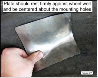
37. Hold the driver-side rear support doubler plate up into position against the bottom of the wheel well, centered under the four mounting holes (Figure 27).
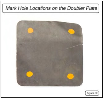
38. With the doubler plate held in position, have someone mark the location of the mounting holes from the inside of the vehicle using a center punch or marker. There must be a minimum of ¼” between the edge of the doubler plate and the edge of each mounting hole (Figure 28).
39. Drill out the holes in the doubler plates to 7/16” diameter and set them aside for later installation.
40. Repeat Steps 37-39 for the passenger-side rear support doubler plate.
Plastic Panel Modifications
The plastic quarter panels must be modified to allow the roll bar and rear supports to pass through. Use the following steps to properly trim the panels:
Quarter Panel Top Cap
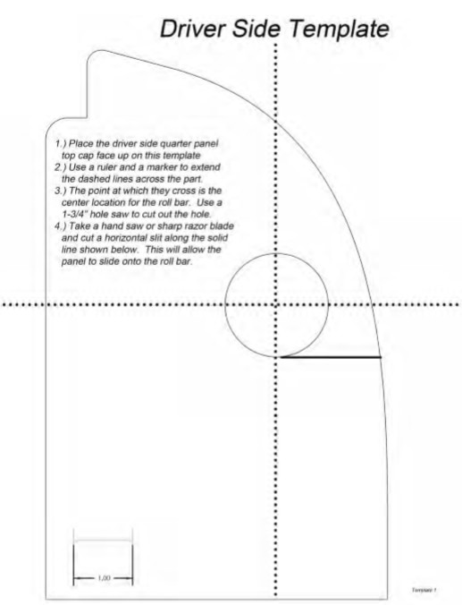
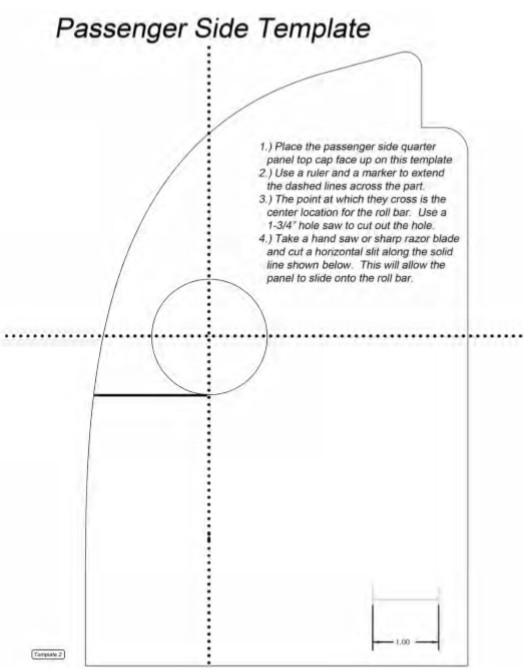
Two templates are provided on Pages 16-17 of these installation instructions to aid in marking the location to trim the quarter panel top caps for clearance around the main hoop.
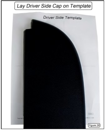
41. Lay the driver-side cap face up on the driverside template (Figure 29 & Template 1).
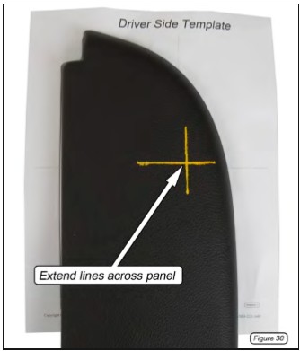
42. Use a ruler to extend the horizontal and vertical lines from the template across the cap until they cross. The point at which they cross is the center of the roll bar tube (Figure 30).
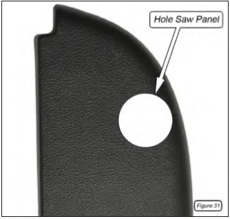
43. Using a 1-3/4” hole saw, cut a hole through the cap where the two marked lines cross (Figure 31).
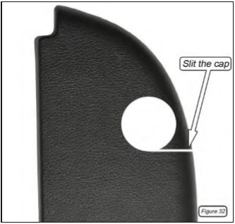
44. Using a wood saw or sharp razor blade, slit the cap along the inboard section of the horizontal line so it can be slid onto the main hoop (Figure 32).
45. Repeat Steps 41-44 for the passenger-side cap using Template 2.
Quarter Panel Rear Support Cutout
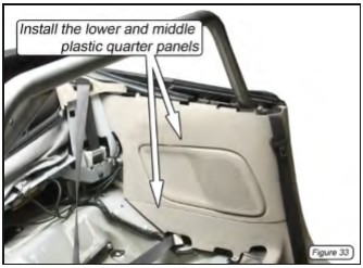
46. Remove the driver-side rear support from the main hoop and place the hoop back into the vehicle.
47. Install the lower and middle portion of the driver-side plastic quarter panel (Figure 33).
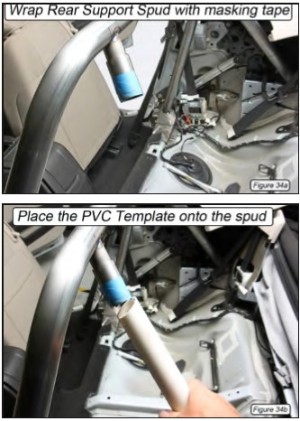
48. Place the supplied PVC template onto the driver-side rear support spud (Figure 34a & 34b).
NOTE: Wrap the rear support spud with a couple layers of masking tape. This will reduce the gap between the ID of the PVC template and the OD of the spud and more accurately locate the end of the PVC.
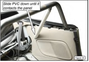
49. Set the roll bar back in its mounting position and install the mounting hardware. Slide the PVC template down until it contacts the plastic quarter panel. Rotate the template so the end is parallel to the face of the panel (Figure 35).
50. Use a marker to trace around the PVC template, the location where the rear support will pass through the plastic panel.
51. Remove the middle section of the plastic panel from the vehicle and hole saw through the location marked for the rear support. Use a hole saw to cut the main opening, then a grinding wheel or sharp razor blade for the remaining material.
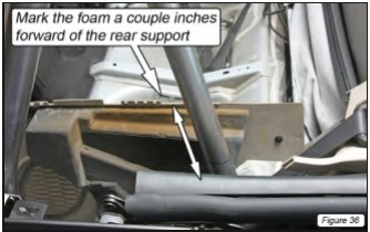
52. Temporarily hold the panel in position and mark the foam a couple inches forward of where it contacts the rear support. Cut the hard foam backing from the plastic panel (Figure 36).
53. Cut a slit from the rearward edge of the hole made in Step 51 to the rearward edge of the plastic quarter panel. The slit should be parallel to the rear support. This will allow the panel to be slid onto the rear support during installation. Use sandpaper or a file to remove any burrs from the edge of the plastic panel (Figure 37).
54. Check the fitment of the panel and trim as necessary (Figure 37).
55. Repeat Steps 46-54 for the passenger side of the vehicle with the driver-side rear support installed and the passenger-side rear support removed.
Do you want to die? If not, pay attention to this:
The rear braces must be welded to the main hoop. That step is not optional. The rear spuds are not structural; they are there only to align the rear braces to the main hoop for easy welding. If the rear braces are not welded to the hoop and the car rolls over, you will probably be killed because the spuds will break off the hoop and allow the roll bar to collapse. Follow the instructions and properly weld the rear braces to the main hoop. Check the MM Facebook page and website for a graphic example of how good the MM roll bars are when properly installed.
Welding the Rear Supports
56. With both rear supports attached, place the roll bar back into its mounting position and verify that all of the holes for the main hoop and rear support mounting pads line up with the holes in the vehicle. We highly recommend inserting all of the mounting bolts to guarantee that the holes line up.
57. Tighten the bolts holding the rear supports to the rear support spuds so the supports cannot move.
58. Remove the roll bar from the vehicle, with the rear supports firmly attached.
59. With the roll bar out of your car, have a qualified welder use either the MIG or TIG welding process to weld the rear braces to the main hoop.
The stubs that the rear braces bolt to are there only to properly locate the rear braces.
They are not structural. Take care to have the rear braces welded to the main hoop itself, and not just to the locating stubs. Take care to keep welding warpage to a minimum to ensure the roll bar fits back into the car properly. Welding must be free of any slag and/or porosity. The NHRA prohibits any grinding of welds.
NOTE: If desired, remove the bolts from the rear supports and plug weld the holes shut once the supports have been welded to the main hoop.
Painting the Roll Bar
60. We recommend painting or powdercoating the roll bar and its components to protect them from rust. Do NOT grind on any of the welds when prepping the roll bar for paint.
Roll Bar Installation
NOTE: Have at least two people help when setting the roll bar into its final position, and be patient.
61. Wrap the rear support tubes with something (such as tape, paper, or cloth) to protect them from scratches during installation. 62. Place the roll bar into the vehicle.
NOTE: The wiring harnesses should pass along the outboard sides of the main hoop.
63. Reinstall ALL the mounting hardware for the main hoop and rear supports before tightening any of the bolts. Use 3/8”-16 x 1”-long bolts with a 3/8” G8 washer under the bolt head.
64. Torque the roll bar mounting bolts to 33 lb-ft.
65. Reconnect the hydraulic cylinder actuator lines removed in Step 17 to the plastic retaining clips located below the rear passenger safety belt.
66. Reinstall the convertible top main pivot L-Brackets removed in Step 16 and torque the mounting bolts to 20 lb-ft.
67. Reinstall the pivot arms disconnected in Step 15 and tighten the mounting bolts to 7 lb-ft.
68. Reinstall the safety belt D-rings removed in Step 8 and torque the bolts to 30 lb-ft.
69. Reconnect the wiring harness to the seat belt retractors located on the B-pillar.
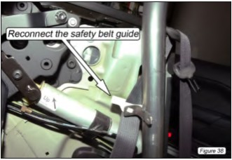
70. Reconnect the white plastic safety belt guides to the square cutout in the L-Brackets welded to the vertical section of the main hoop (Figure 38).
Speaker Panel Modification
71. Starting with the driver-side speaker bracket, remove the speaker.
72. Lay the speaker mounting bracket on a flat surface and draw a horizontal line across the forward face of the bracket (Figure 39).
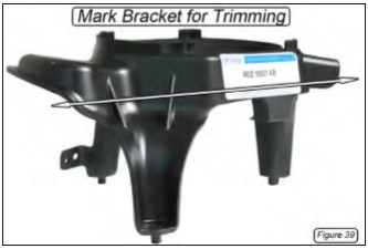
73. Trim the bracket along the line so there’s no material left below the line.
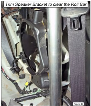
74. Place the speaker bracket into position on the vehicle and mark any areas where it makes contact with the roll bar. There should be at least a 1/8” gap between the two.
75. Continue to trim and test fit the speaker bracket until it clears the roll bar (Figure 40).
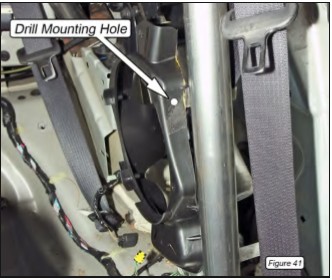
76. Once satisfied, place the speaker bracket into position and drill a 1/8” hole through the bracket, inline with the hole in the L-bracket welded to the vertical portion of the Main Hoop (Figure 41).
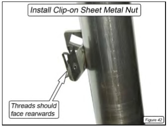
77. Place one of the provided clip-on sheet metal nuts onto the L-bracket, with the threaded portion facing rearward (Figure 42).
78. Connect the wiring harness to the speaker bracket and install the bracket into position using the two factory screws and one of the provided #8 sheet metal screws. Gently tighten the screws.
79. Reconnect the wiring harness to the speaker and install it into the speaker bracket using the four factory mounting screws.
80. Repeat Steps 71-79 for the passenger side.
Quarter Panel Installation
81. Hold the lower part of the panel in position.
82. Mark where the panel touches the rearward corner of the MM Support Bracket (Figure 43).
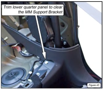
83. Trim the panel to clear the support bracket.
84. Reinstall the lower portion of the quarter panel. Be sure to insert the two push-pin retainers on each panel; one is located at the front of the seat bulkhead and the other atop the bulkhead, adjacent to the seatbelt retractor.
85. Reinstall the middle portion of the quarter panel. Slide the rear support cutout hole over the rear support first, and gently work the panel down into position.
86. Insert the one push-pin at the upper, rearmost point of the panel.
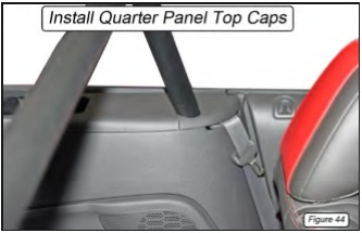
87. Slide the quarter panel top caps onto the main hoop and clip into position (Figure 44).
Final Installation
88. Reinstall the rear seat backrest cushions. Torque the two 13mm hex head backrest bolts to 17 lb-ft.
89. Reconnect the convertible top to the back of the seat backrest.
90. Reinstall the rear lower seat cushion.
91. Reinstall the door scuff plates.
92. Reinstall the rear wheels and lower the vehicle to the ground. Torque the lug nuts to the manufacturer’s recommended value.
NOTE: Roll bar padding must be installed on any areas of the roll bar that the vehicle occupants may possibly contact during an accident. his includes any parts of the roll bar that the occupants’ hands, arms, legs, and feet may contact, as well as the head.