FREE 1 to 3-Day Delivery on Orders $149+ Details
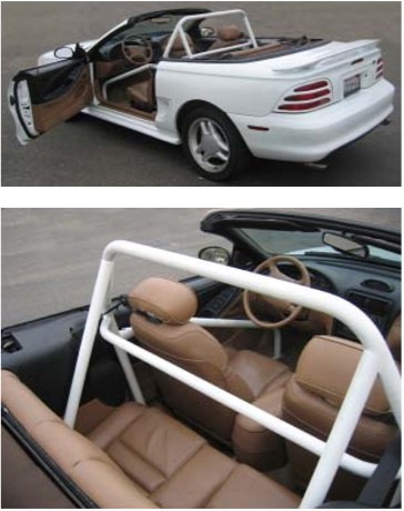
How to Install Maximum Motorsports 6-Point Drag Race Roll Bar w/ Fixed Harness Mount (94-04 Convertible) on your Ford Mustang

Shop Parts in this Guide
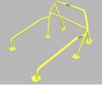
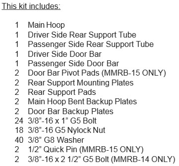
The Maximum Motorsports 6-point Drag Race Roll Bar is designed to meet the NHRA rules with proper installation. It is made from 1-3/4" x 0.134" wall DOM tubing (which exceeds the NHRA requirements of 0.118" ERW tubing). The harness mount tube is 11/2" x 0.134" wall DOM (NHRA minimum requirement is 1-1/4" ERW). Mounting pads and reinforcing plates are all 6" x 6" x 1/8".
To meet the NHRA rules, the Weld-on Reinforcement Plates must be fully welded to the vehicle. Have a qualified welder, preferably certified, use either a MIG or TIG welder. Take care to keep warping to a minimum. Remember that the NHRA prohibits any grinding of the welds. Welding must be free of any slag and/or porosity. Note that while the NHRA does require door bars, the door bars are not required to be welded to the main hoop. A bolted or pinned connection is acceptable. We recommend that you have your own copy of the latest NHRA rules. You can get your copy by calling them at (626) 914-4761.
Read all instructions before beginning work. Following instructions in the proper sequence will ensure the best and easiest installation.
1. Lower the convertible top down.
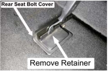
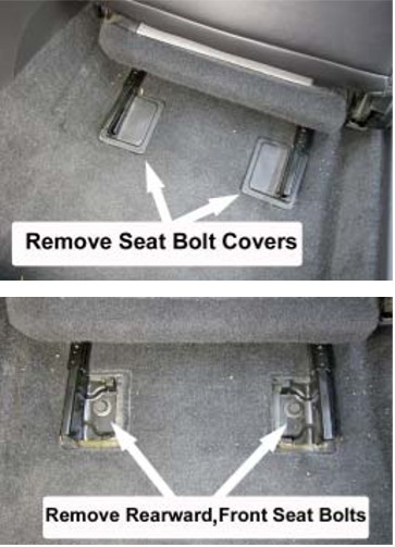
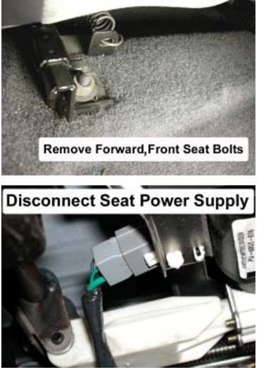
2. Remove the front seats by first removing the plastic covering the rear mounting bolts. Remove the two rear bolts and the two front nuts retaining each seat. Disconnect the power supply for the seat adjustment motor, if so equipped.
NOTE: Depending on the year of your vehicle the plastic covers will vary.
OR
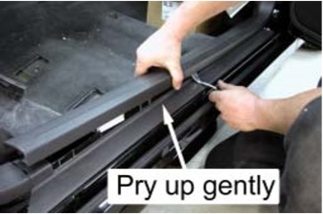
3. Remove the doorsill plates from each side of the vehicle. Use a flat screwdriver to help lift the sill plates away from the carpet.
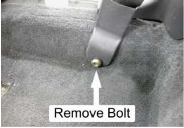
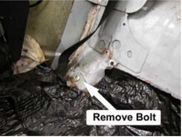
4. Using a T-50 Torx tool, remove the driver and passenger seat belts where they connect to the inner portion of the rocker panels.
NOTE: If your vehicle has a seat belt retractor mechanism located at the inner portion of the rocker panel, you must remove its plastic cover to gain access to the mounting bolt.
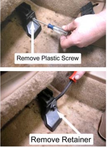
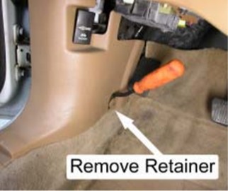
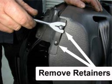
5. Remove the plastic retainer from the driver and passenger side kick panels.
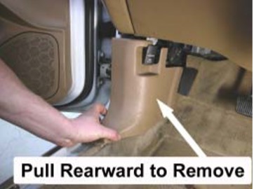
6. Remove the driver and passenger side kick panels by carefully pulling them rearward.
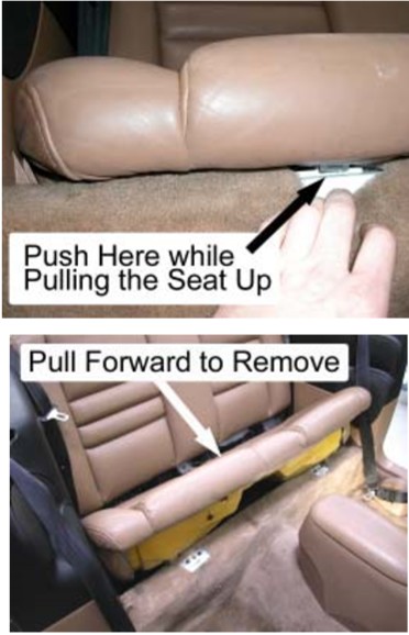
7. Remove the rear lower seat from the vehicle by depressing the two cushion release buttons, located underneath the front of the seat cushion, and pulling upward.
8. If there is a sound-deadening mat located beneath the rear seat, carefully remove it.
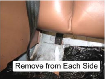
9. Remove the rear seatback from the vehicle by first removing the retaining screw holding each lower corner of the seatback to the vehicle. Then, carefully pull the seatback straight up and out of the vehicle.
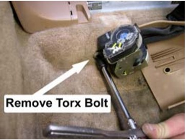
10. Using a T-50 Torx tool, remove the driver and passenger rear seat belts where they attach to the vehicle, beneath the rear lower seat cushion.
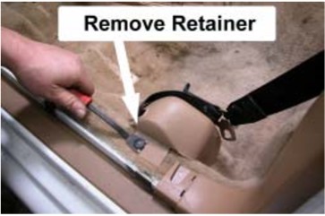
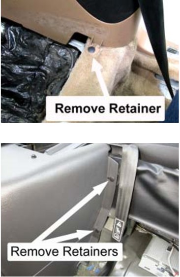
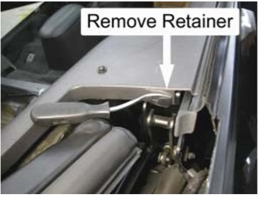
11. Remove the two small plastic retainers that are located on the forward face of the driver and passenger rear plastic side panels. Take care to avoid damage to the rubber door seal flap.
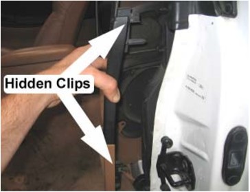
12. Begin removal of the driver and passenger rear plastic side panels by first removing the four plastic retainers holding each side panel to the vehicle. Then pull the panels away from the BPillar.
NOTE: There are two hidden clips attached to each plastic side panel, one located at the top and one located at the center of the panel where it attaches to the B-Pillar. Some effort may be required to pull the plastic side panels free from the B-Pillar.
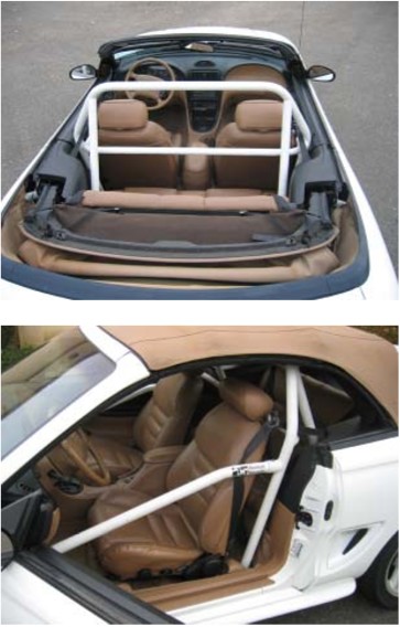
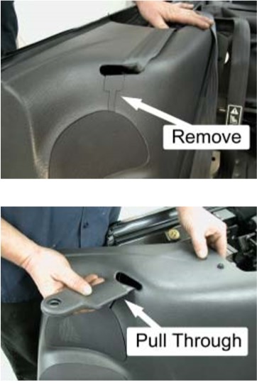
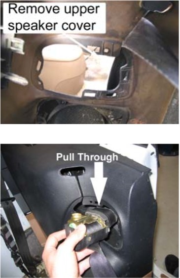
13. Pull the driver and passenger side seat belts through the access holes located on the plastic side panels. Depending on the year of your vehicle, the design of the access holes will vary. Follow the pictures (below) that correspond to the design of your plastic side panels.
14. Pull the carpet up and away from each corner of the floor pan.
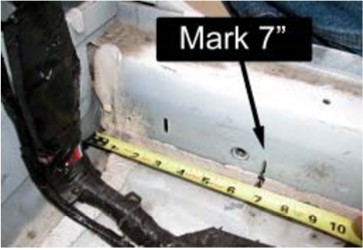
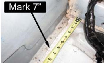
15. Starting at the rear corner of the driver side floor pan, make a mark 7" forward of the corner, along the rocker panel. Repeat for the passenger side.
16. Again, starting at the rear corner of the driver side floor pan, make a mark 7" inward from the corner, along the rear bulkhead. Repeat for the passenger side.
17. Using a wood chisel or other sharp scraping tool, remove any seam sealer located between the corners of the floor pan and the marks made in the previous steps. It is important to remove the seam sealer so that the Main Hoop Mounting Pads will be properly seated on the floor pan.
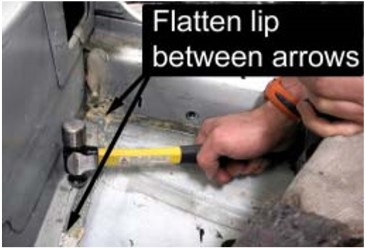
18. Working parallel to the rear bulkhead where the seam sealer has been removed, carefully hammer down the raised sheet metal lip on the driver and passenger side.
Weld-on Reinforcement Plate Installation
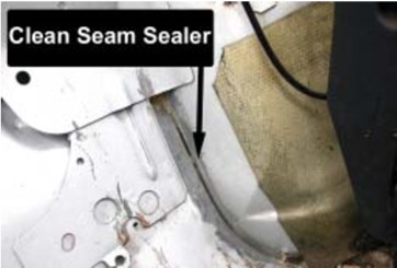
19. Using a wood chisel or other sharp scraping tool, remove any seam sealer present where the rear inner wheel well meets the floor pan in the passenger compartment of the vehicle.
NOTE: In order to prevent porosity during welding, it is important to remove as much of the seem sealer as possible. A wire wheel in an electric drill or a wire brush will aid in removing any small remnants of seem sealer.
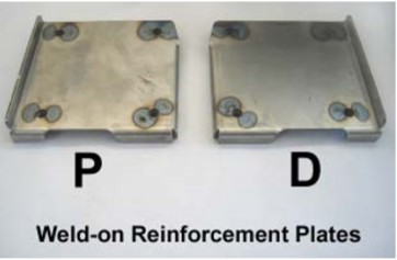
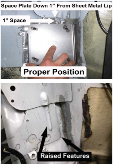
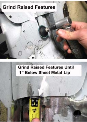
20. The Weld-on Reinforcement Plates are located in the vehicle as shown in the photo below. The stock floor pan area where the Plates will be located has two raised features that prevent the Plates from sitting flat on the floor pan. It is necessary to remove these raised features for proper installation. Using a grinding wheel, grind the raised features flush with the surrounding floor pan.
NOTE: Do NOT hammer these raised features down. Doing so will distort the floor pan and not allow the Weld-on Reinforcement Plates to be properly installed.
21. Hold the driver side Weld-on Reinforcement Plate as shown in the previous step and use a marker to outline its location. Repeat for the passenger side Plate.
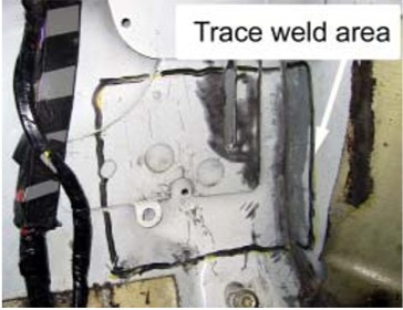
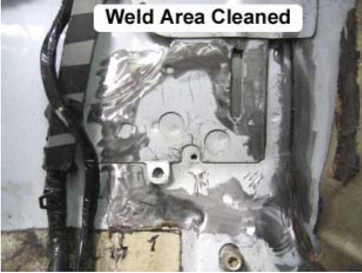
22. Using a power sander, carefully sand away any paint within ½” on either side of the outline made in the previous step. The paint must be fully removed to allow proper welding of the Weld-on Reinforcement Plate to the vehicle.
NOTE: Avoid excessive sanding, as the sheet metal can be easily damaged.
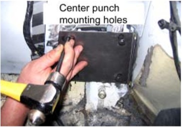
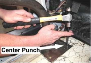
23. Position the driver side Weld-on Reinforcement Plate as shown below. Use a center punch to mark the location of each hole on the floor pan. Repeat for the passenger side Plate.
24. Using a 1/8" or similar sized drill bit, create a pilot hole at each of the center punch marks.
NOTE: Make sure that there are no brake or fuel lines beneath the floor pan that you could accidentally drill through.
25. Using progressively larger drill bits or a Uni-bit, drill to a 1/2" final hole diameter.
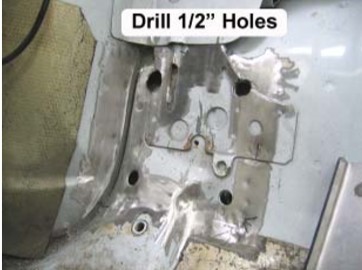
26. Reposition the driver side Weld-on Reinforcement Plate so that four pre-welded nuts on the backside of the Plate are centered over the 1/2" drilled holes. The top half of the pad should be resting flush with the floor pan and touching the inner fender well.
NOTE: The two upper nuts must be recessed into the 1/2" holes so that the top of the Plate is touching the floor pan. If they are not recessed into the holes, it will be necessary to slightly enlarge the holes using a hand file, or the next largest drill bit.
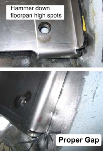
27. The goal of this step is to make as much of the lower half of the Weld-on Reinforcement Plate touch the floor pan as is possible. Due to Ford’s production tolerances, some vehicles may require more work than others to make the Weld-on Reinforcement Plates fit properly. Begin by noting where the bent tabs of the Weldon Reinforcement Plate touch the floor pan. Remove the Plate and use a small hammer to tap the floor pan down around those contact points. Put the Plate back into position and check for contact. Repeat this procedure until the entire lower perimeter of the Plate is within 1/16" of the floor pan.
NOTE: In some cases, it may be easier to grind away a portion of the bent tabs in order for the Weld-on Reinforcement Plate to rest properly against the floor pan.
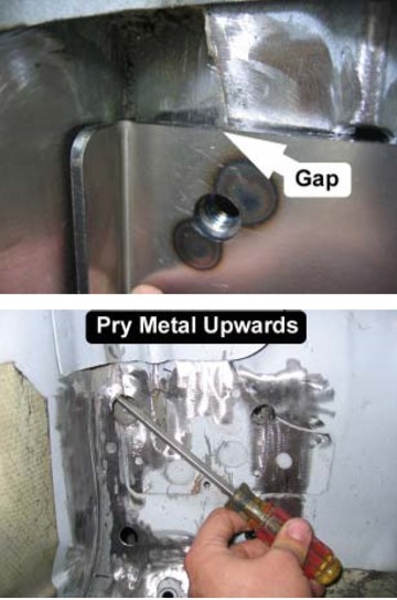
NOTE: On some vehicles the upper, outboard corner of the Weld-on Reinforcement Plates will be spaced away from the floor pan. If this occurs, place a screwdriver through the adjacent ½” hole that was drilled in Step 25 and carefully pry the sheet metal upwards to minimize the gap.
28. Repeat Steps 26-27 for the passenger side.
29. Safely support the rear of the vehicle on jack stands and remove the rear wheels.
30. Disconnect the ground terminal at the battery.
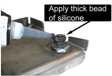
31. Place a large bead of silicone around the external surface of the welded nuts, on the bottom side of the Weld-on Reinforcement Plates. The silicone will prevent water and other debris from entering through the ½” holes after the Plates are welded to the vehicle.
32. Place a large bead of silicone around the perimeter of the ½” holes drilled in Step 25.
The next steps will require welding inside of your vehicle. If using a MIG welder, take extra care to cover anything within a 4-6 foot radius of the welding location that you do not want damaged from sparks. The welding sparks will easily cause burn damage to the wiring harness, convertible top, seat belts, speakers, exterior paint, window glass, and anything else non-metallic that they come in contact with. Also, make sure you have a fire extinguisher and a bucket of water handy if something does catch on fire.
EXTREMELY Helpful Welding Tip:
Do NOT attempt welding a bead longer than 1 inch at a time. Instead, weld for 1 inch and then skip 1 inch before welding the next section. By skipping 1 inch between weld beads, the metal will have time to dissipate enough heat to lower the chances of burning through the sheet metal. Once you have welded one side of the Plate in this fashion, you can return to the beginning of your weld, and weld in the 1-inch gaps.
CAUTION: ALWAYS wear a respirator and provide good ventilation when welding to the sheet metal of the vehicle. The anti-corrosion coating used to protect the vehicle WILL vaporize during the welding process and will usually emit a pale yellow smoke. This vapor is extremely hazardous and should not be inhaled.
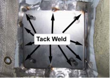
33. Place the driver side Weld-on Reinforcement Plate in the vehicle and place three small tack welds across the top edge of the Plate. Examine the rest of the Plate to make sure that it is contacting the floor pan. If the Plate is not making proper contact, grind off the tack welds and reposition the Plate again.
34. Place three small tack welds across the bottom edge of the Plate, three small tack welds down the interior edge of the Plate, and two small tack welds down the exterior edge of the Plate.
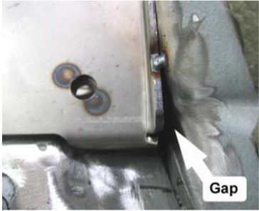
NOTE: There will be a small gap between the bottom of the exterior edge and the interior fender well.
35. Starting at the top, exterior edge of the Weld-on Reinforcement Plate, begin welding the Plate to the vehicle. Continue welding the edge until you reach the gap pictured below.
NOTE: Have a friend pay close attention to the exterior fender well as the rubber coating may burn during welding. Use a damp rag to smother the fire. Avoid dousing the flame with water as this may cool the metal too rapidly and possibly weaken the welded joint.
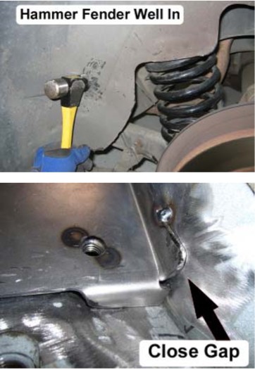
36. Using a small hammer, bend the lower portion of the flange towards the fender well until the gap is reduced by half.
37. Using a small hammer from the exterior side of the fender well, gently tap the sheet metal inwards until the gap in Step 36 is closed.
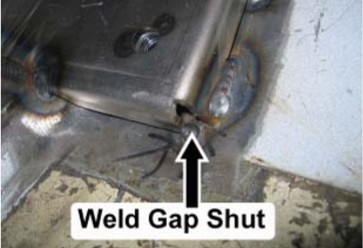
38. Weld the bottom edge of the Weld-on Reinforcement Plate to the vehicle.
39. Weld the interior edge of the Weld-on Reinforcement Plate to the vehicle.
40. Weld the top edge of the Weld-on Reinforcement Plate to the vehicle.
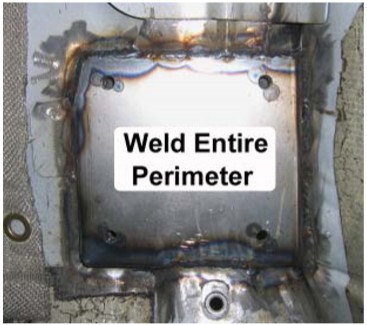
41. Finish welding the Weld-on Reinforcement Plate to the vehicle. The entire perimeter of the Plate MUST be welded to the vehicle to meet the NHRA requirements.
42. Repeat Steps 33-41 for the passenger side of the vehicle.
43. Reinstall the rear wheels and torque the lug nuts to factory specifications.
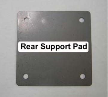
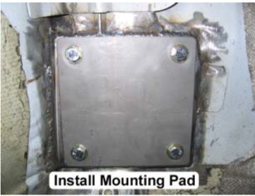
44. Take the supplied four-bolt Rear Support Pads with the evenly spaced holes and bolt them to the Weld-on Reinforcement Plates using the supplied 3/8" x 1" G5 bolts and a 3/8" G8 washer underneath each bolt head.
NOTE: Make sure the threads of the nuts on the Weld-on Reinforcement Plates are free of any weld spatter or other debris that may damage them. Use a small bottlebrush to help clean them out.
45. Temporarily reinstall the driver and passenger side rear plastic side panels.
46. Temporarily reinstall the rear lower seat cushion.
47. Place the Main Hoop in the vehicle. Make sure that the wiring harness on the driver side of the vehicle is on the outboard side of the Main Hoop.
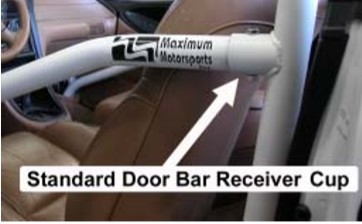
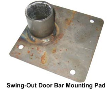
48. Install the driver and passenger side Door Bars. If using Standard Door Bars, make sure the Door Bars are fully inserted into the Receiver Cups that are welded to the Main Hoop. If using the Removable Swing-Out Door Bars, install the Pivot Pads onto the ends of the Door Bars before inserting the supplied ½” quick pins into the Main Hoop Mounting Tabs.
49. Reconnect the negative terminal of the battery.
50. Put the convertible top up and secure the latches.
NOTE: Position the Hoop so that it does not obstruct the top from closing.
Positioning the Main Hoop
51. Position the Main Hoop Mounting Pads as far rearwards in the vehicle as possible. If you find the Main Hoop touches the rear plastic side panels, shift the Hoop forward until there is roughly a ¼” gap.
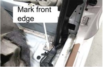
52. Mark the front edge of the Main Hoop Mounting Pads.
53. Close the driver and passenger side doors.
54. Note the distance between the top corners of the Main Hoop and the steel frame of the convertible top. Position the Hoop so that the distance on the passenger and driver side is equal.
NOTE: It is helpful to have a friend aid in positioning the Main Hoop.

55. Double check that the Main Hoop is lined up with the marks made in Step 52.
56. Once you are satisfied with the position of the Main Hoop, carefully open the doors and center punch through the holes in the driver and passenger side Main Hoop Mounting Pads.
57. Put the convertible top down and slide the Main Hoop forward so that you can gain access to the center punch marks.
NOTE: You may temporarily need to remove the Door Bars to slide the Main Hoop forward.
58. Using a 1/8" or similar sized drill bit, create a pilot hole at each of the center punch marks.
NOTE: Make sure that there are no brake or fuel lines beneath the floor pan that you could accidentally drill through.
59. Drill the pilot holes out to a diameter of 3/8".
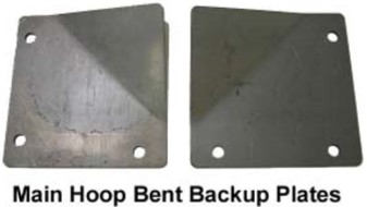
60. Reposition the Main Hoop and attach the supplied Main Hoop Bent Backup Plates underneath the Hoop using the supplied 3/8"x 1" G5 bolts, 3/8" Nylock nuts, and 3/8"G8 washers. There should be three bolts securing each Main Hoop Mounting Pad.
NOTE: The Main Hoop Bent Backup Plates are driver and passenger side specific. Make sure the three holes in the Bent Backup Plates match the holes in the Main Hoop Mounting Pads before bolting them to the Hoop.
61. Torque the Main Hoop mounting bolts to 32 lb-ft. The floor pan will slightly distort as the bolts are tightened.
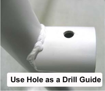
62. Using the hole in the downward bent portion of the Main Hoop Mounting Pads as a guide, drill a 3/8" hole through each Bent Backup Plate.
63. Install the supplied 3/8" x 1" G5 bolts, 3/8" Nylock nuts, and 3/8" G8 washers in each of the drilled holes and torque to 32 lb-ft.
64. Trim the carpet around the Main Hoop as required.
Positioning the Door Bars
The installation method for both the Standard Door Bars and the Removable Swing-Out Door Bars is identical. However, if using the Standard Door Bars, make sure that each Door Bar is fully inserted into its Receiver Cup before continuing.
65. Temporarily move the wiring harness adjacent to the Door Bar Mounting Pads upwards, so that the holes in the Mounting Pads are visible.
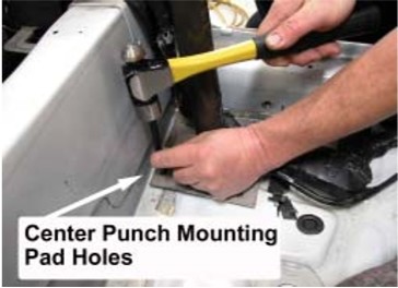
66. Push the Door Bars outboard, until the Mounting Pads touch the rocker panel, then center punch each of the Mounting Pad holes.
67. After removing the Door Bars, create a pilot hole at each of the center-punched marks using a 1/8" or similar sized drill bit.
68. Drill the pilot holes out to a diameter of 3/8".
69. Reinstall the Door Bars and place the supplied 3/8" x 1" G5 and 3/8" G8 washers into each of the Mounting Pad holes.
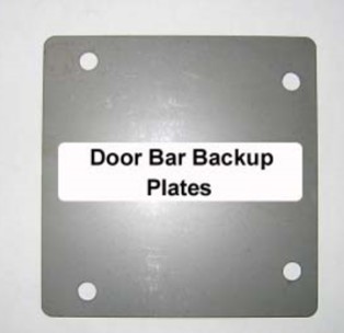
70. Attach the remaining Door Bar Backup Plates underneath each Door Bar Mounting Pad. Secure the Backup Plates and Door Bar Mounting Pads using the remaining 3/8" Nylock nuts and 3/8" G8 washers, and torque the fasteners to 32 lb-ft.
71. If using the Removable Swing-Out Door Bars, remove the ½” quick pins and check that the Door Bars swing in and out easily. Occasionally, after bolting the Door Bar Mounting Pads in place, the Door Bars will not realign with the tabs welded to the Main Hoop. If this occurs, gently push on the end of the Door Bar in the appropriate direction to bend the sheet metal surround the Mounting Pad, and realign the Door Bar to the Main Hoop.
72. If using the Standard Door Bars, use the holes in the Door Bar Receiver Cup as a guide to drill a 3/8" hole for the Door Bar mounting bolts.
NOTE: Drill from both the top and bottom of the Receiver Cups to ensure that the holes are aligned.
73. If using the Standard Door Bars, install the supplied 3/8" x 2-½” G5 bolts and 3/8" Nylock nuts in each Door Bar Receiver Cup, but do not tighten yet.
74. Trim the carpet around the lower portion of the Door Bar as required.
Rear Support Installation
The Rear Supports are left intentionally long to allow a custom installation in each vehicle. They are prenotched to mate to the Main Hoop. The angled cut on the bottom (rearward) end is at the correct angle. When trimming to the correct length for you car, cut the tube at this same angle.
NOTE: The Rear Supports MUST be installed at an angle of at least 30° from vertical to meet the NHRA requirements.
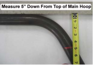
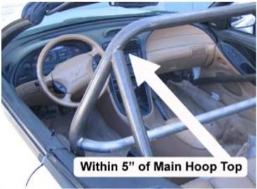
NOTE: The tops of the Rear Supports MUST be within 5" of the top of the main hoop to meet the NHRA requirements.
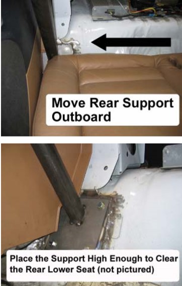
75. Using a tape measure, mark a line on each side of the Main Hoop that is 5" from the top of the Hoop. The top of the Rear Supports must be positioned above this line. Do NOT weld them if they are below this line, as that will not meet the NHRA rules. At the same time, do not position them too much closer than 4” as they will move inboard, away from the plastic side panels, where they will encroach on the rear seat and passenger area.
76. Starting on the passenger side, position the Rear Support so that it is resting on the Main Hoop and the Rear Support Pad. See the photos below for proper positioning of the Rear Support. The Rear Support MUST touch the plastic side panel to allow installation of the rear seat back.
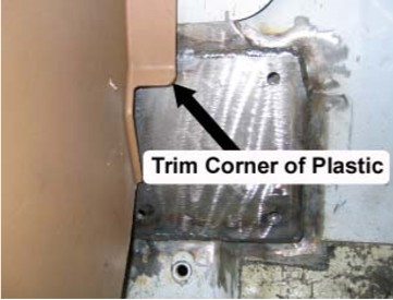
NOTE: It may be necessary to trim the lower corner of the plastic side panel in order to locate the Rear Support properly.
77. Use an angle finder to measure the angle of the Rear Support. If the angle is less than 30° from vertical, the Rear Support must be shortened so that the angled end can be positioned higher up on the Rear Support Pad while keeping the notched end at the same location on the Main Hoop. Be sure the car is at normal ride height and on level ground when measuring this angle.
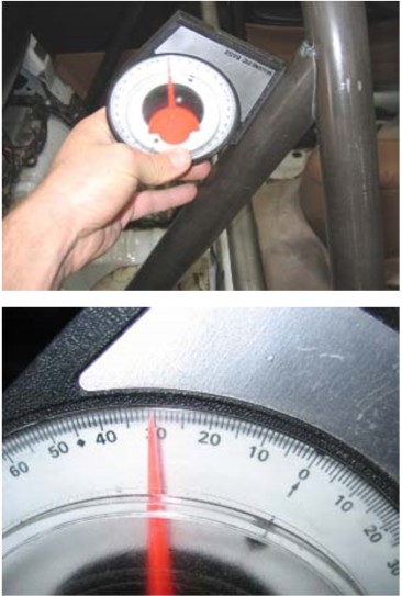
78. Using a hacksaw or other cutting tool, remove about 1/8" – 3/16" of material from the angled (lower) end of the Rear Support. Make sure to cut the Rear Support Tube end parallel to the existing angle.
79. Reposition the Rear Support and check the angle. Once you have reached 30° or more, place several tack welds to hold the Rear Support in place.

80. Repeat Steps 76-79 for the driver side of the vehicle.
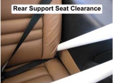
81. Next, place the rear seat back into position. Note where the seat back mounting tabs interfere with the Rear Supports.
NOTE: The rear seat back should be able to slide in between the Rear Supports. If the Rear Supports have been placed too far inboard, the rear seat back will not be able to be installed properly. If necessary, remove the tack welds and reposition the Rear Supports further outboard.
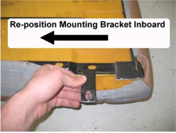
82. Trim the seat back mounting tabs from the seat so that they can be welded further inboard on the seat’s frame.
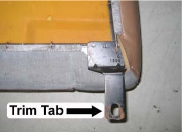
83. Re-position the mounting tabs inboard and weld them to the seat frame. Be careful to protect the upholstery from welding sparks.
84. Check that the rear seat back can be properly installed before continuing.
NOTE: New mounting holes must be drilled to attach the re-positioned rear seat mounting tabs.
85. Once you are satisfied with the position of the Rear Supports, remove the rear seats and finish welding the Rear Supports to the Main Hoop and the Rear Support Pads. NOTE: Be sure to disconnect the negative battery terminal before welding to the vehicle.
86. Unbolt and completely remove the Roll Bar from the vehicle. Apply a coat of primer and paint to any unprotected metal surfaces on the chassis.
87. This is also the time to powder coat or paint the roll bar itself.
88. Reinstall the Roll Bar and the interior back into the vehicle. Torque all the Roll Bar mounting bolts to 32 lb-ft.
NOTE: The rear plastic side panels should be installed simultaneously with the Main Hoop.
NOTE: Some kits may include additional hardware not required for the installation of your particular roll bar.