FREE 1 to 3-Day Delivery on Orders $149+ Details
How to Install Maximum Motorsports 6-Point Drag Race Roll Bar w/ Fixed Harness Mount (94-04 Coupe) on your Ford Mustang
Tools Required
- T-50 Torx Bit
- Standard assortment of hand tools
- 15mm wrench and socket
- 17mm wrench and socket
- 9/16” wrench and socket
- Torque wrench
- Power Drill
- 3/8” drill bit
- 7/16” drill bit
- 2” Hole saw
- Hacksaw or wood saw
- Center punch
- 1/8” drill bit

Shop Parts in this Guide
Read all instructions before beginning work. Following instructions in the proper sequence will ensure the best and easiest installation.
The latest version, high-quality COLOR instructions are available online at www.maximummotorsports.com. Check the bottom of these installation instructions for the date and compare it to the copy available online.
Do you want to die? If not, pay attention to this:
The rear braces must be welded to the main hoop. That step is not optional. The rear spuds are not structural; they are there only to align the rear braces to the main hoop for easy welding. If the rear braces are not welded to the hoop and the car rolls over, you will probably be killed because the spuds will break off the hoop and allow the roll bar to collapse. Follow the instructions and properly weld the rear braces to the main hoop. Check the MM Facebook page and website for a graphic example of how good the MM roll bars are when properly installed. With MM’s innovative design, the rear braces bolt to the main hoop, which holds them in the correct position so they can be welded while outside of the car. This unique design reduces shipping charges, and saves you the time and effort of stripping the interior of your car to protect it from welding sparks.
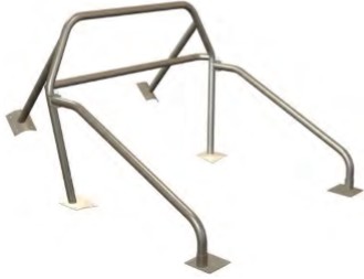
The Maximum Motorsports 6-point Drag Race Roll Bar is designed to meet the NHRA rules with proper installation. It is made from 1-3/4” x 0.134” wall DOM tubing (which actually exceeds the NHRA requirements of 0.118” ERW tubing). The harness brace is 1-1/2” x 0.134” wall DOM (NHRA minimum requirement is 1-1/4” ERW). Mounting pads and reinforcing plates are all 6” x 6” x 1/8”. The version with swingout door bars allows easy access for daily drivers.
Note that the NHRA DOES allow the door bars to bolt to the main hoop. We recommend that you have your own copy of the latest NHRA rules. Call them at (626) 914-4761.
NOTE: Due to the required welding for an NHRA installation, the MM roll bars are shipped uncoated. For best results, we suggest that you complete the installation, then remove the roll bar for either painting or powdercoating, and then reinstall. That way you will avoid wear and tear on your finish while drilling holes.
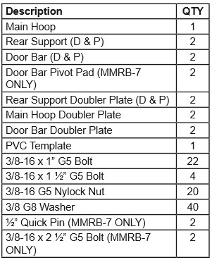
This kit contains:
Interior Removal/Preparation
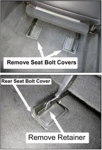
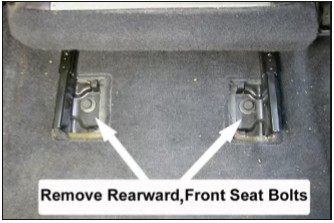
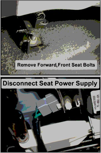
1. Remove the front seats by first removing the plastic covering the rear mounting bolts. Remove the two rear bolts and the two front nuts retaining each seat. Disconnect the power supply for the seat adjustment motor, if so equipped.
NOTE: Depending on the year of your vehicle, the plastic covers will vary.
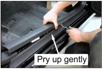
2. Remove the doorsill plates from each side of the vehicle. Use a flat screwdriver to help lift the sill plates away from the carpet.
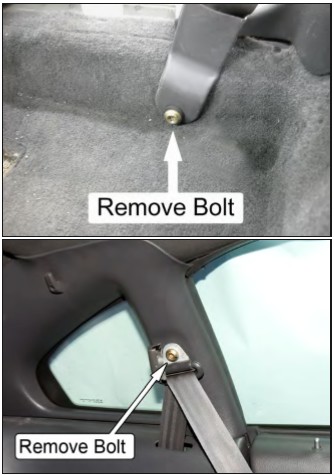
3. Using a T-50 Torx tool, remove the driver and passenger seatbelts where they connect to the inner portion of the rocker panels and to the upper section of the B-pillars.
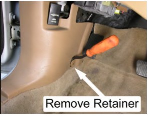
4. Remove the plastic retainer from the driver- and passenger-side kick panels.
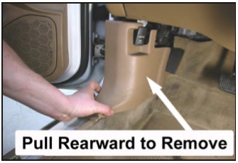
5. Remove the driver- and passenger-side kick panels by carefully pulling them rearward.
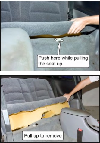
6. Remove the rear lower seat from the vehicle by depressing the two cushion release buttons, located underneath the front of the seat cushion, and pulling upward.
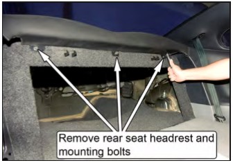
7. Remove the rear seat headrest. Most are retained using three bolts that are visible when the rear seats are folded down.
NOTE: Some headrests may have three clip-style retainers located on the backside of the head rest. Gently pull up one end of the headrest to disengage the clips.
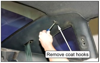
8. Unscrew the coat hooks and remove them.
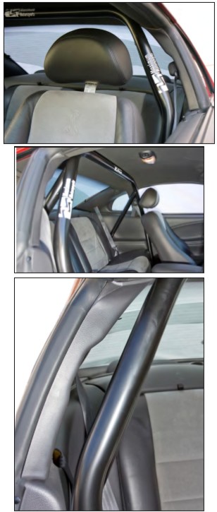
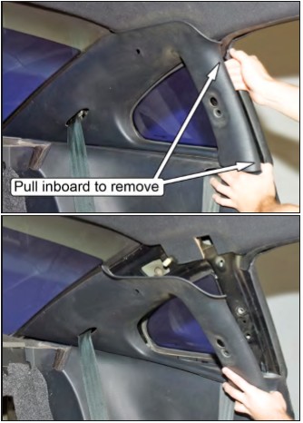
9. Remove the upper plastic quarter panels. They snap into place using retaining clips located on the backside of the panel. Remove the panel by pulling inboard on the upper B-pillar edge until you hear it unsnap. Then, gently pull on the lower B-pillar edge of the panel until it comes loose.
NOTE: If the retaining clips remain in the vehicle, use a pair of pliers to pull them out so that they can be reinstalled on the panel.
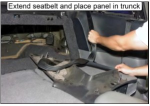
10. With the rear seats folded down, extend the rear seatbelts so that the panels can be placed in the trunk area, out of the way.
11. Remove the two small plastic retainers that are located on the forward face of the driver and passenger lower plastic quarter panels. Take care to avoid damage to the rubber door seal flap.
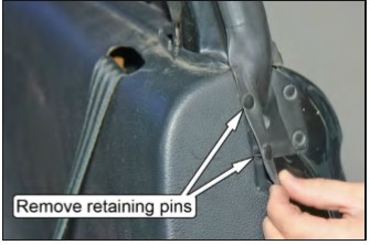
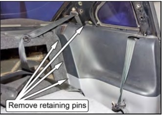
12. Remove the four retaining pins holding each lower plastic quarter panel in place. One pin is located beneath the quarter window, and the other three are behind the rear seat backs.
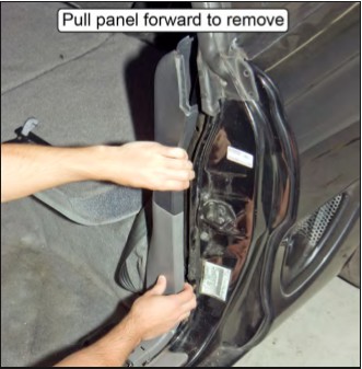
13. Remove the lower plastic quarter panels by pulling forward on the B-pillar edge. Once the panels unsnap, angle them out and over the rear seat bulkhead.
NOTE: There are two hidden clips on each panel, one located at the top and one located at the center of the panel where it attaches to the B-pillar. Some effort may be required to pull the plastic side panels free from the B-pillar.
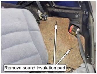
14. Remove the sound insulation pad located over each wheel. Pull out the two plastic push pins retaining each pad.
15. Pull the carpet up and away from each corner of the floor pan.
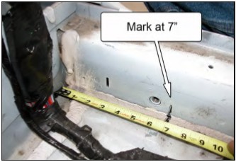
16. Starting at the rear corner of the driver-side floor pan, make a mark 7” forward of the corner, along the rocker panel. Repeat for the passenger side.
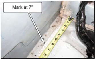
17. Again, starting at the rear corner of the driverside floor pan, make a mark 7” inward from the corner, along the rear bulkhead. Repeat for the passenger side.
18. Using a wood chisel or other sharp scraping tool, remove any seam sealer located between the corners of the floor pan and the marks made in the previous steps. It is important to remove the seam sealer so that the main hoop mounting pads will be properly seated on the floor pan.
19. Working parallel to the rear bulkhead where the seam sealer has been removed, carefully hammer down the raised sheet metal lip on the driver and passenger side.
Main Hoop Installation
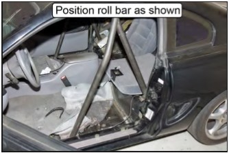
20. Insert the main hoop into the vehicle without the rear supports attached. This will take two people.
21. Bolt each rear support to its respective side of the main hoop with the 2-1/4” bolts and Nylock nuts, once the hoop is inside the car.
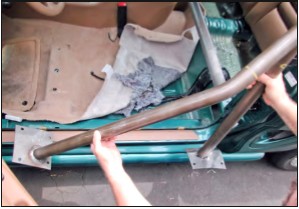
22. Position the main hoop mounting pads against the rear seat bulkhead and center the main hoop in the car by positioning the mounting pads an equal distance from each rocker panel. The rear support mounting pads should sit on top of the wheel wells.
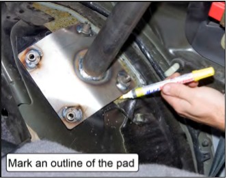
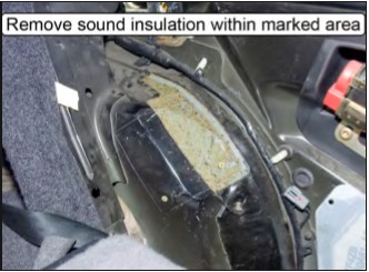
23. Mark the outline of the rear support mounting pads onto both wheel wells.
24. Move the main hoop forward and chisel away the sound insulation within the marked area on each rear wheel well. The rear mounting plates must rest directly against the metal of the wheel well.
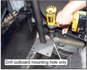
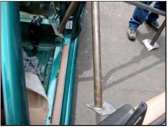
25. Set the main hoop back into place and drill through the forwardmost, outboard mounting hole on the driver-side main hoop mounting plate using a 3/8” drill bit. Place one of the provided 3/8-16 x 1”-long bolts into the drilled hole.
NOTE: Check the bottom side of the car before drilling for fuel or brake lines.
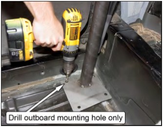
26. Drill through the forwardmost, outboard mounting hole on the passenger-side main hoop mounting plate using a 3/8” drill bit. Place one of the provided 3/8-16 x 1”-long bolts into the drilled hole.
NOTE: Check the bottom side of the car before drilling for fuel or brake lines.
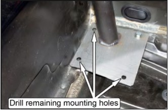
27. Drill the three remaining holes in each of the main hoop mounting plates. It will be necessary to mark the outboard hole and temporarily move the hoop to allow access for the drill.
28. Mark the position of the four mounting holes in each rear support mounting pad onto the wheel well using a center punch.
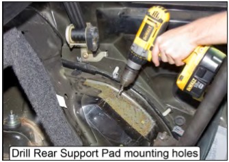
29. Move the main hoop forward and drill the four holes marked on each wheel well out to a 7/16” diameter. Use 1/8” diameter pilot drill to start the holes.
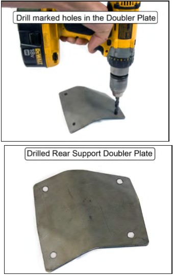
30. Hold the driver-side rear support doubler plate up into position against the bottom of the wheel well, centered under the four mounting holes. With the doubler plate held in position, have someone mark the location of the mounting holes from the inside of the vehicle using a center punch or marker.
NOTE: There needs to be a minimum of 3/8” between the edges of the doubler plate and the marked holes. A shorter distance indicates that the doubler plate position needs to be adjusted slightly.
31. Drill out the holes in the doubler plate to 7/16” diameter and set it aside for later installation.
32. Repeat Steps 30-31 for the passenger-side rear support doubler plate.
Plastic Quarter Panel Modifications
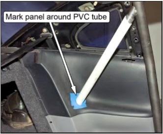
The lower plastic quarter panels must be modified to allow the rear supports to pass through. A section of PVC pipe has been included to aid in marking the panel for modification. Use the following steps to properly trim the panels.
33. Unbolt the driver-side rear support from the main hoop and reinstall the lower plastic quarter panel on that side of the car.
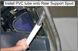
34. Slide the PVC tube over the driver-side rear support spud and move the main hoop back into its mounting position. Install one of the provided 3/8-16 x 1”-long G5 bolts into each of the main hoop mounting pads to help locate the hoop.
NOTE: If the PVC tube is loose on the rear support spud, wrap the spud with a piece of tape before installing the tube to increase the diameter and create a tighter fit.
35. Slide the angled end of the PVC tube down against the quarter panel. Rotate the PVC tube so the end is parallel to the face of the panel and mark the panel around the outside of the tube.
NOTE: To avoid marring the panel, affix some strips of masking tape over the areas to be marked.
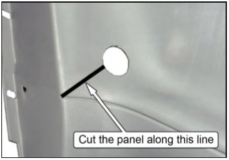
36. Remove the rear half of the plastic panel from the vehicle and hole saw through the location marked for the rear support. Use a 2” hole saw if available, or a 1-3/4” hole saw can be used and the opening can be filed out larger.
37. Mark a line from the lower, inboard edge of the hole to the corner of quarter panel, where the horizontal seam line runs.
38. Use a fine-toothed saw to cut the panel along this line.
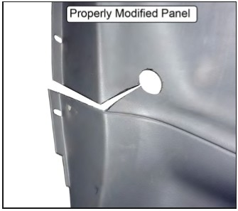
39. Continue the cut along the horizontal seam line, all the way to the rear of the panel. This will allow the panel to be slid onto the rear support during installation. Use sandpaper or a file to remove any burrs from the edge of the plastic panel.
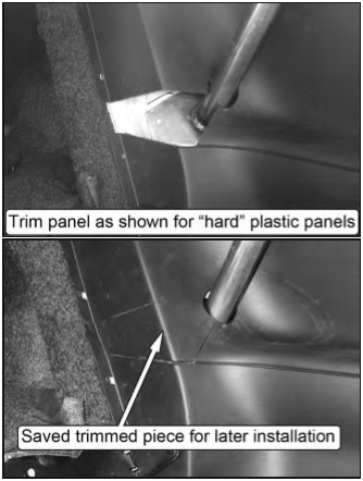
NOTE: 1994-98 vehicles use a less flexible plastic for the quarter panels that can’t be spread apart. They require removal of a section of the panel to allow installation onto the rear supports. Remove a section of the panels as shown below.
40. Repeat Steps 33-39 for the passenger side of the vehicle.
Do you want to die? If not, pay attention to this:
We repeat: The rear braces must be welded to the main hoop. That step is not optional. The rear spuds are not structural; they are there only to align the rear braces to the main hoop for easy welding. If the rear braces are not welded to the hoop and the car rolls over, you will probably be killed because the spuds will break off the hoop and allow the roll bar to collapse. Follow the instructions and properly weld the rear braces to the main hoop. Check the MM Facebook page and website for a graphic example of how good the MM roll bars are when properly installed.
Welding the Rear Supports
41. Reattach the rear supports to the main hoop and check that all bolt holes still line up correctly with the chassis.
42. Tighten the bolts securing the rear supports to the main hoop so that they can not move.
NOTE: Do not unbolt the rear supports from this point on.
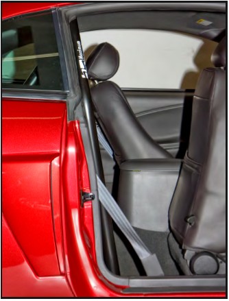
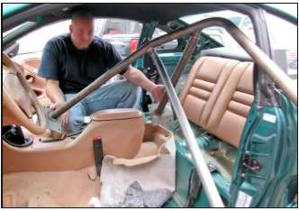
43. Remove the roll bar from the vehicle. Slide it forward while rotating top of the hoop back until it can fit through the driver-side door. Two or three people and patience will help this job go smoothly.
44. Have a helper hold the driver-side door open as wide as possible to avoid gouging the door with the roll bar mounting pads.
45. Pull the driver-side rear support past the B-pillar and out the door.
46. Continue to pull the roll bar out the door. Make sure the main hoop mounting pads clear the center console, if present.
47. Keep the roll bar as low to the ground as possible in order to keep adequate clearance on the upper door frame.
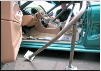
48. Pull the roll bar out the door and slightly toward the rear of the car.
49. Keeping the driver-side mounting pads low, rotate the roll bar up so the passenger-side mounting pads will clear the lower door frame.
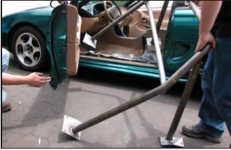
50. Again, have a helper hold the driver-side door open as wide as possible to avoid damage to the door.
51. Rotate the roll bar toward the rear of the car so the front mounting pad comes out the door.
52. Make sure the rear support mounting pad clears the lower door frame and B-pillar, and complete the removal of the roll bar.
53. With the roll bar out of your car, have a qualified welder use either the MIG or TIG welding process to weld the rear braces to the main hoop.
The stubs that the rear braces bolt to are there only to properly locate the rear braces. They are not structural. Take care to have the rear braces welded to the main hoop itself, and not just to the locating stubs.
Take care to keep welding warpage to a minimum to ensure the roll bar fits back into the car properly. Welding must be free of any slag and/ or porosity. The NHRA prohibits any grinding of welds.
NOTE: If desired, remove the bolts from the rear supports and plug weld the holes shut once the supports have been welded to the main hoop.
54. We recommend painting or powdercoating the roll bar and its components to protect them from rust. Do NOT grind on any of the welds when prepping the roll bar for paint.
Roll Bar Installation
55. Reinstall the roll bar into the car. Follow the same procedure you used for removal, only in reverse (Steps 43-52).
56. Position the roll bar so the rear support pads are resting near the rear seat bulkhead.
57. If desired, reinstall the sound insulation pads removed in Step 14. A couple strips of tape can be used to hold them up, off the wheel wells, until the roll bar is installed.
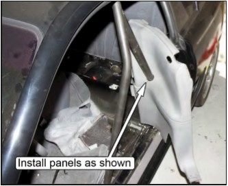
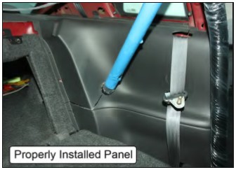
58. Install the lower plastic quarter panels onto the rear supports. Spread the panel apart along the cut made in Step 39 and gently slide it over the rear support. The front half of the panel should be resting outboard of door openings.
NOTE: To help protect the freshly painted rear supports, we recommend wrapping them with paper, plastic, or masking tape along their entire length.
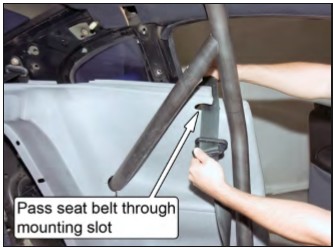
59. Pass the seat belts up through the mounting slots in the quarter panels and hang them over the inboard edge.
60. Using at least two people, slide the roll bar back into its final mounting position. As the roll bar is moved back, the lower plastic quarter panels must be gently forced over the rear seat bulkhead into their original mounting position.
NOTE: The forwardmost foam blocks glued to the plastic quarter panels WILL make it difficult to move the roll bar into position. Removal of these blocks will allow an easier installation, but is not necessary.
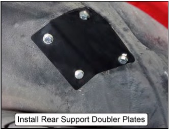
61. Install the rear support doubler plates. Use 3/8”-16 x 1”-long bolts and 3/8” G8 washers beneath the bolt heads. Only thread the bolts in a few turns for now.
62. Install the main hoop doubler plates. Use 3/8”-16 x 1”-long bolts, 3/8”-16 Nylock nuts, and 3/8” G8 washers beneath the bolt heads and nuts.
63. Torque the main hoop mounting pad bolts to 33 lb-ft.
64. Torque the rear support mounting pad bolts to 33 lb-ft. NOTE: Applying silicon sealer around each bolt will help prevent future leaks.
65. Drill the fourth hole through the main hoop doubler plates using a 3/8” drill bit, and the main hoop mounting plate as a guide.
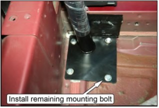
66. Install the remaining bolts for both main hoop mounting plates and torque to 33 lb-ft. Use 3/8”16 x 1- 1/2”-long bolts, 3/8”-16 Nylock nuts, and 3/8” G8 washers beneath the bolt heads and nuts.
NOTE: It may be helpful to press up on the corner of the main hoop doubler plate using a small jack to help minimize the gap between the floor pan while installing the mounting bolt.
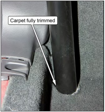
67. Trim the carpet to accommodate the main hoop, and reattach it to the rear seat bulkhead.
68. Fully seat the lower plastic quarter panels into their original position and reinstall the plastic retainer pins removed in Steps 11-12.
69. Reinstall the rear lower seat.
70. Reinstall the rear seat headrest.
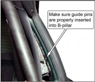
71. Reinstall the upper plastic quarter panels.
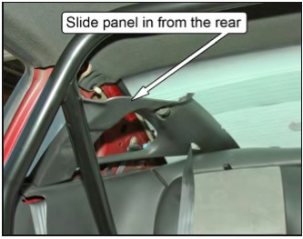
NOTE: Each panel has a long plastic guide pin located near the front and rear of the panel. Make sure these pins are inserted into their respective mounting holes in the sheet metal for proper installation.
72. Reinstall the coat hook screws and any remaining quarter panel retaining hardware.
73. Reattach the seatbelts to the B-pillar and rocker panel. Torque the bolts to 30 lb-ft.
Positioning the Door Bars
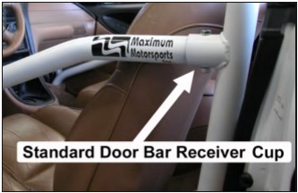
The installation method for both the standard door bars and the removable swing-out door bars is identical. However, if using the standard door bars, make sure that each door bar is fully inserted into its receiver cup before continuing. If using the swing-out door bars, the quick release pins should be installed.
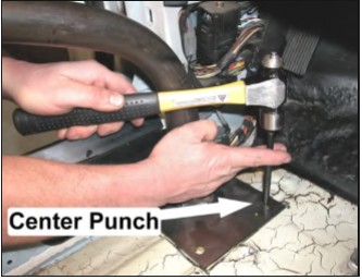
74. Temporarily move the wiring harness adjacent to the door bar mounting pads upward so the holes in the mounting pads are visible.
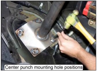
75. Push the door bars outboard until the mounting pads touch the rocker panel, then center punch each of the mounting pad holes.
76. After removing the door bars, create a pilot hole at each of the center-punched marks using a 1/8” or similar-sized drill bit.
77. Drill the pilot holes out to a diameter of 3/8.”
Final Installation
78. Reinstall the front seats and plastic cover plates.
79. Reinstall the door bars and place the supplied 3/8” x 1” G5 and 3/8” G8 washers into each of the mounting pad holes.
80. Attach the remaining door bar backup plates underneath each door bar mounting pad. Secure the backup plates and door bar mounting pads using the remaining 3/8” Nylock nuts and 3/8” G8 washers, and torque the fasteners to 32 lb-ft.
81. If using the removable swing-out door bars, remove the ½” quick pins and check that the door bars swing in and out easily. If the door bars do not realign with the tabs welded to the main hoop, gently push on the end of the door bar in the appropriate direction to bend the sheet metal to surround the mounting pad, and realign the door bar to the main hoop.
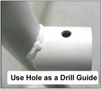
82. If using the standard door bars, use the holes in the door bar receiver cup on the front of the main hoop as a guide to drill a 3/8” hole for the door bar mounting bolts.
NOTE: Drill from both the top and bottom of the receiver cups to ensure that the holes are aligned.
83. If using the standard door bars, install the supplied 3/8” x 2-½” G5 bolts and 3/8” Nylock nuts in each door bar receiver cup and tighten.
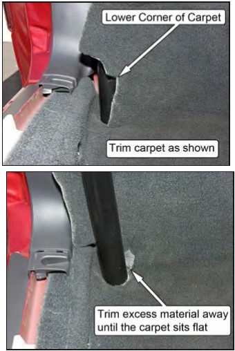
84. Trim the carpet around the lower portion of the door bar as required.
85. Install the remaining kick panels and door sill plates.
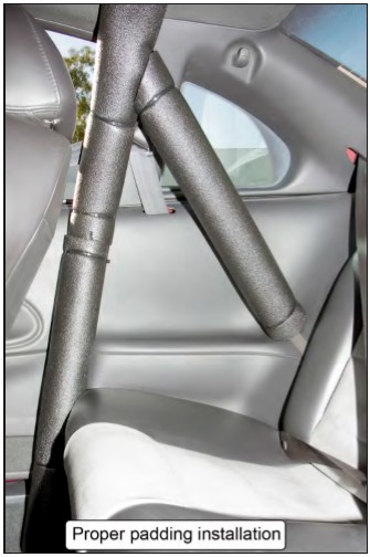
NOTE: Roll bar padding must be installed on any areas of the roll bar that the vehicle occupants may possibly contact during an accident. This includes any parts of the roll bar that the occupants’ hands, arms, legs, and feet may contact, as well as the head.