 FREE 1 to 3-Day Delivery on Orders $149+ Details
How to Install Maximum Motorsports Drag Race Adjustable Rear Lower Control Arms (99-04 All, Excluding Cobra) on your Ford Mustang
Installation Time
4 hours
Tools Required
- 18mm Socket
- 18mm & 19mm Wrench
- Standard Hand Tools
- Floor Jack
- 2 Jackstands
- 100+ ft-lb Torque Wrench
- Socket for Lug Nuts

Shop Parts in this Guide
Read all instructions before beginning work. Following instructions in the proper sequence will ensure the best and easiest installation.
MMRLCA-35.1 requires a rear swaybar that does not attach to the rear lower control arms, such as the Maximum Motorsports Adjustable Rear Swaybar.
The MM Drag Race Adjustable Rear Lower Control Arms are rated for a 3800lbs and lighter vehicles, running slower than 1.2 second 60ft times. Cars with 1,000 RWHP will need these control arms.
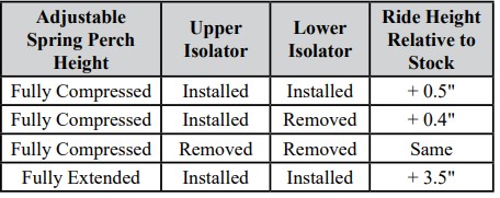
The following ride heights can be achieved when using these arms:
Required Supplemental Items
• Pry bar
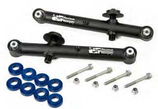
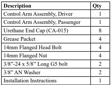
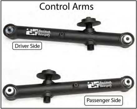
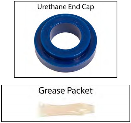
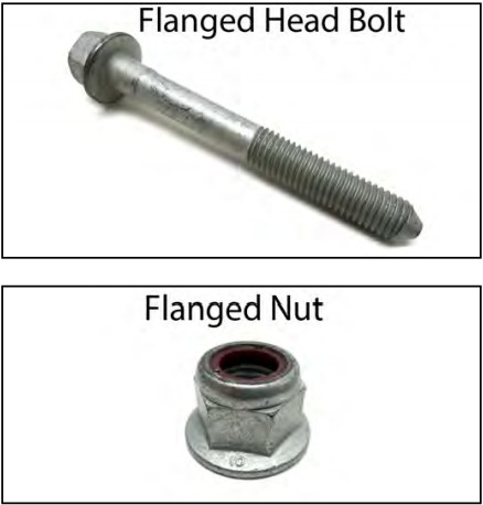
This Kit Contains
Component Identification
Installation
1. Safely jack up the rear of the car, and support the chassis with jackstands placed under the pinch welds.
2. Block the front wheels to keep the car from rolling.
3. Jack up the rear axle enough to place jack stand under the axle tubes.
4. Lower the rear axle, to a height just above full droop, so that it is supported by the jack stands.
5. Remove the rear wheels. NOTE: Work on one side of the car at a time. Do not remove both rear lower control arms at the same time. All photos show the passenger side.
6. Remove the rear swaybar. There are four bolts, two per side. On 1994 and newer cars with rear disk brakes, the Parking Brake Cable Bracket is attached to the rearward swaybar bolt.
7. Working on the passenger side first, loosen the two lower control arm pivot bolts.
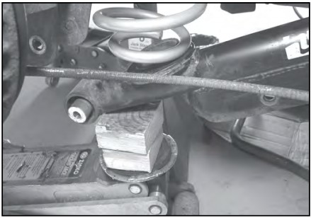
8. Support the control arm near the axle mount with a jack. Remove the lower control arm pivot bolt from the axle end. Slowly lower the jack to release the spring tension. Be careful not to lower it too quickly or else the spring may suddenly pop out, causing injury. Once the spring is completely uncompressed, remove it from the car.
9. Remove the control arm pivot bolt from the chassis and remove the control arm from the car.
ABS Bracket Modification
If the vehicle is not equipped with ABS, skip to the Control Arm Installation Section starting with Step 18.
10. Unclip the ABS wire from the bracket.
11. Disconnect the passenger side parking brake cable from the brake caliper by removing the retainer clip and slipping the end of the cable off of the caliper.
12. The configuration of the Parking Brake Cable and ABS Brackets must be changed. Disconnect the parking brake cable from the caliper. To do this, remove the E-clip and pull on the end of the cable with pliers to unseat the cable end from the caliper. Make sure the parking brake is off!
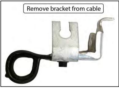
13. Remove the Parking Brake Cable Bracket from the cable.
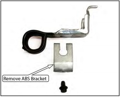
14. Remove the ABS Bracket.
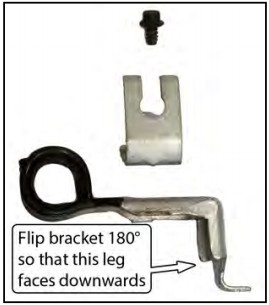
15. Flip the Parking Brake Cable Bracket 180 degrees and place the ABS Bracket on top of the Parking Brake Cable Bracket.
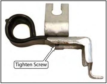
16. Tighten the ABS Bracket screw.
17. Slide the Parking Brake Cable Bracket back onto the parking brake cable and reattach the parking brake cable to the caliper.
Control Arm Installation
18. Apply a coating of the supplied grease to both the inside diameter, and the small step on the outside diameter of the Urethane End Caps.
19. Install the Urethane End Caps into both ends of the MM Control Arms.
20. Reattach the control arm to the chassis using the provided hardware. NOTE: The welded nut on the control arm must face outwards.
21. Install the lower spring isolator on the MM Control Arm.
22. Place the spring on the control arm and raise the arm into position with the jack. Be sure the spring is correctly seated into both the upper and lower perches.
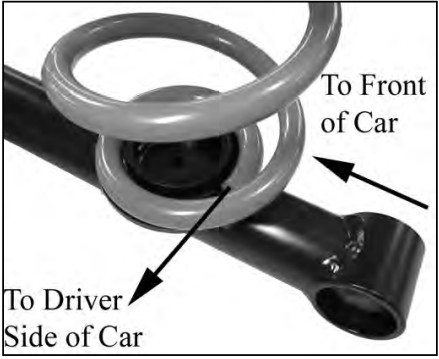
NOTE: If using stock style springs, the spring’s “pig tail” should be oriented towards the rear of the car, as shown below
23. Install one of the provided flanged head bolts into the rearward pivot, at the axle housing. NOTE: If a MM Panhard Bar is installed on the vehicle, reuse the longer pivot bolt supplied with it for the driver side pivot location.
24. Torque the chassis side flanged head bolt to 111 ft-lb.
25. Torque the axle side flanged head bolt to 111 ftlb.
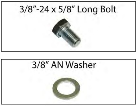
26. Attach the Parking Brake Cable Bracket to the nut welded onto the control arm using the supplied bolt and washer. Torque to 35 ft-lb.
27. Reattach the ABS wire if present.
28. Repeat Steps 7-27 for the driver side control arm.
29. Install a Maximum Motorsports Adjustable Rear Swaybar if the car does not already have one.
30. Verify the parking brake works from inside the car. Adjust to factory specifications if necessary.
31. Reinstall the rear wheels.
32. Lower to the ground and torque the lug nuts.
33. Using a 1/2“ drive ratchet/extension, adjust the spring perch adjustment bolts to set the rear ride height. Recheck after driving and adjust as necessary. Grease periodically to insure smooth operation of the adjusting bolt.
NOTE: MM uses special close tolerance bearings. These typically take 100-200 miles to break in. Until the break-in period is over the car will ride more firmly--it will seem like it has stiffer rear springs.
