 FREE 1 to 3-Day Delivery on Orders $149+ Details
How to Install Maximum Motorsports Front Coil-Over Conversion Kit for Bilstein Struts (79-04 All) on your Ford Mustang

Shop Parts in this Guide
Read all instructions before beginning work. Following instructions in the proper sequence will ensure the best and easiest installation.
Thank you for purchasing Maximum Motorsports’ ultimate coil-over conversion kit manufactured specifically for MM and Bilstein Struts. There are many features you will find that set our coil-over kit apart from the rest.
• Starting at the top, we maximize bump travel by providing an assortment of spacers to properly position the upper spring perch under the strut tower.
• Our upper spring perch assembly, shaped far better than others on the market, has been designed for optimum strength, clearance, and bump travel.
• Two O-rings seal the thrust needle bearings to keep dirt and water out, and the grease in.
• The lower spring perch is drilled for easy adjustment with a spanner wrench, if pre-loading the spring is necessary.
• A set screw ensures that the lower spring perch will never move.
• While other companies simply anodize their aluminum parts for appearance, we have critical components hard anodized, at over twice the cost, for maximum durability.
• Suspension loads from the threaded sleeve are fed into a clamp collar. That provides a large contact area, keeping the sleeve from galling on the strut ears.
• Overlooked by other companies, our threaded sleeve assembly is designed to fit the strut snugly. A tight fit keeps the threaded sleeve from rattling on the strut. More importantly, the lower spring perch is kept square to the strut, preventing the spring from arcing and rubbing on the threaded sleeve.
• Finishing off the kit, we use only the highest quality springs on the market. Our extensive technical knowledge of rates, free lengths, and proper spring travel ensures that your car will perform to the max.
• We include dust boots to help protect your strut shaft from dirt and debris. Dirt and debris can damage seals and shorten the service life of your strut.
With the use of a Coil-Over Kit, the entire front weight of the car is now transmitted through the pivot of your Caster/Camber (C/C) plates; you should use a well-designed steel C/C plate with a high-quality spherical bearing. Rubber or urethane C/C plate bushings will not be able to handle the load without excessive deformation and possible failure. Most aluminum C/C plates are not strong enough for coil-over applications. Aluminum C/C plates that are strong enough for use with a Coil-Over kit will be very thick and may unnecessarily reduce bump travel.
The 1979-93 C/C plates only require three bolts because the strut top is captured within a triangle formed by these bolts (as viewed from the top). This means that each bolt carries a relatively equal portion of the vertical strut load, and the load is evenly distributed into the strut towers.
For 1994-04 Mustangs, Maximum Motorsports makes the only C/C plate suitable for use with a Coil-Over kit: our innovative 4-bolt C/C plates. On 1994-04 cars, the strut top is outside of the triangle formed by the three factory mounting bolts (as viewed from the top). With a 3-bolt C/C plate the entire vertical load is carried by two bolts, and the plate is in a cantilevered bending situation. The load is unevenly distributed into the strut tower, resulting in a prying load which may bend the strut towers or result in failure of the C/C plates. MM added a fourth bolt, which results in the strut top being captured within the square formed by the four bolts, (as viewed from the top). Now the load is evenly spread out into the strut towers.
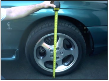
1. Measure the front ride height on both sides of the car. Record the measurements for future reference.
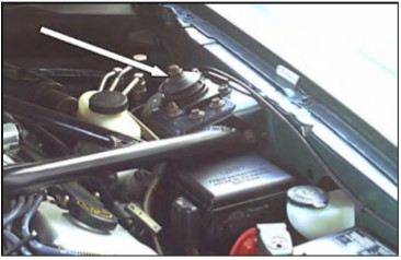
2. Loosen, but do not remove, the strut top retaining nuts.
Then, raise the front of the car and place it securely on jack stands.
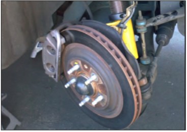
3. Remove both front wheels.
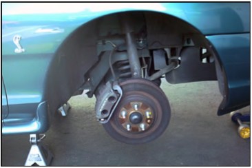
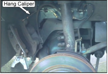
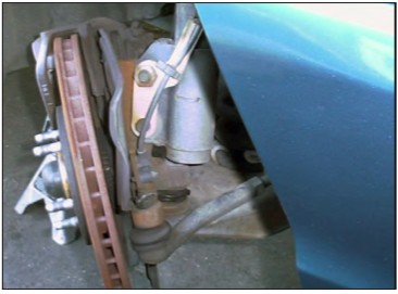
4. Unbolt the brake caliper and hang it securely. Do not let the caliper hang from the brake hose, as this can cause unseen damage to the hose. Steel braided hoses are especially susceptible to damage if the caliper is dropped or allowed to hang unsupported.
5. While it is not necessary, you may find it helpful to remove the brake rotor. Disconnect the outer tie-rod end from the spindle.
6. Disconnect the swaybar end-link from the control arm.
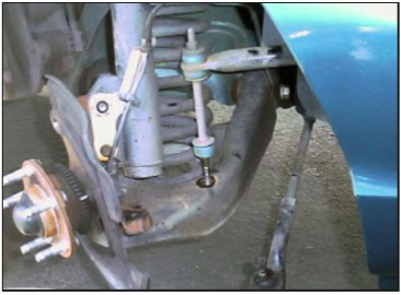
7. If the car is equipped with ABS, carefully unhook the sensor’s wire from the mounting bracket on the strut to get enough slack in the wire to remove the sensor from the spindle. Remove the sensor-to-spindle bolt, and carefully remove the sensor from the spindle. Remove the mounting bracket from the strut.
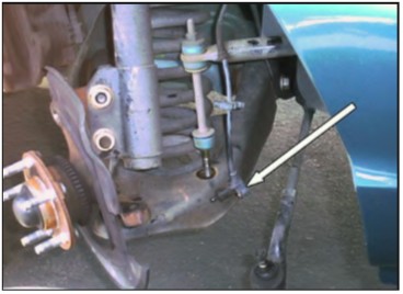
8. Place a floor jack under the control arm, and slightly compress the spring to support the control arm when the strut top retaining nut is removed.
9. Loosen, but do not remove, the two bolts holding the strut housing to the spindle.
10. Remove the strut top retaining nuts.
11. Remove the two bolts that hold the strut housing to the spindle, and carefully remove the strut from the car.
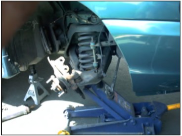
12. Carefully lower the control arm with the jack and remove the spring. If necessary, use a spring compressor. Often, aftermarket springs are shorter and can be gently “popped” out once the control arm is lowered far enough. Stock springs are quite long and require a spring compressor for safe removal.
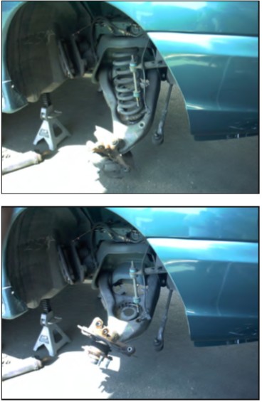
13. Be sure to remove the upper spring isolator. Sometimes they stick to the upper spring perch.
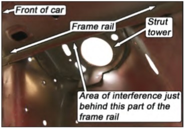
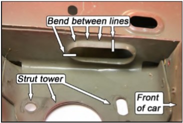
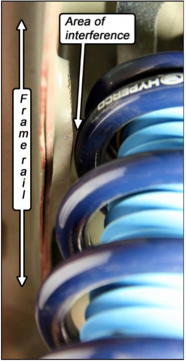
14. On the inboard face of the driver’s side upper frame rail, there is an oval-shaped flange that protrudes from the frame rail. On cars with SN95 (1994-2004) width front control arms, the coil-over spring may contact this flange, causing a clunking noise. The MM Flange Straightener can be used to bend the flange up increasing clearance between it and the spring, eliminating the potential interference.
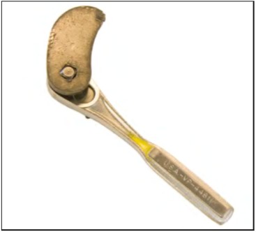
15. Fit the MM Flange Straightener on a 3/8” drive ratchet as shown.
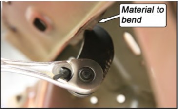
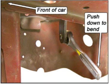
16. Fit the slotted end of the tool over the flange as shown. The flange can be bent by pushing down on the wrench. Reference the photo in the previous step to see where the tool needs to be used.
NOTE: Do NOT attempt to bend the flange flush with the frame rail using the provided tool, as damage to the tool will occur. The tool is only designed to bend the flange ~50° from its starting position. If more clearance is needed, a small hammer can be used.
NOTE: The flange will bend easily, but we do NOT recommend attempting to bend the entire length in one step. Instead, bend the flange approximately 25°, then move the tool forward along the flange in 1/4” increments until the required length of flange is bent. Once done, make another pass, bending the flange the remaining angle. Making smaller bends with the tool rather than one large one will minimize the risk of damaging the tool.
NOTE: If the notch in the tool becomes enlarged, it can be hammered back to its original shape and size.
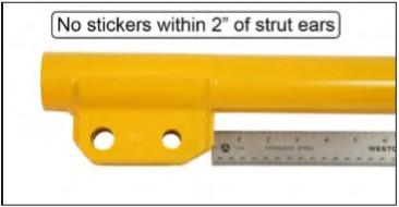
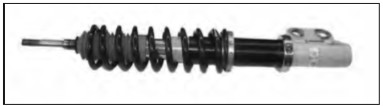
17. Remove all hardware, dust boots, etc., from your MM or Bilstein struts. If there are any stickers within 2” of the top of the strut ears, remove them.
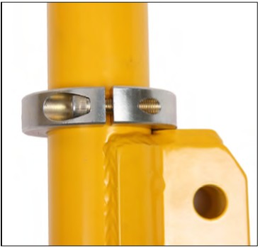
18. Place the Split Clamp Collar around the strut housing. The side of the Split Clamp Collar with the machined groove faces upwards.
19. Rotate the Split Clamp Collar so the bolt openings are positioned at a 90 degree angle from the strut ears.
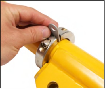
20. Remove the bolt from the rearward position of the Split Clamp Collar and insert the Brake Hose Tab as shown. Reinstall the bolt.
NOTE: The tab is meant to crush slightly when tightened to keep the tab from rotating when installed.
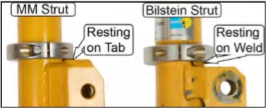
21. Position the Split Clamp Collar as low as possible so that it can clamp evenly on the strut housing. If you have MM Struts, the Split Clamp Collar will contact the top of the spindle mounting ears. If you have Bilstein Struts, the Split Clamp Collar will be in position when it contacts the top of the weld, preventing it from sliding down the strut housing.
22. Evenly turn the Split Clamp Collar bolts to snug the two halves of the Split Clamp Collar together. Tighten the Split Clamp Collar bolts to 25 ft-lbs.
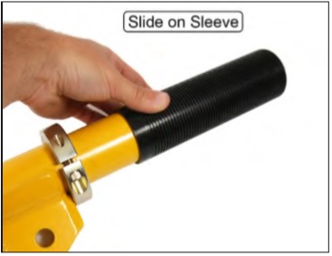
23. Slide the threaded sleeve down over the strut housing, unthreaded end first, until it bottoms against the Split Clamp Collar.
24. Thread the Lower Spring Perch onto the Threaded Sleeve.
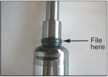
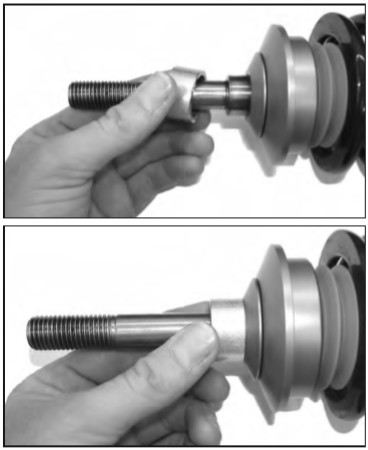
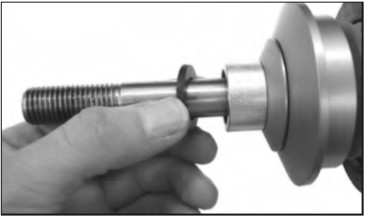
25. Slide the Upper Spring Perch over the strut shaft to check for clearance around the shoulder that is at the top of the large-diameter section of the strut shaft. If the Upper Spring Perch does not clear this shoulder, file the shoulder down until the perch will just fit around the shoulder.
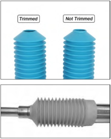
26. Install the bellow-style dust boot onto the strut shaft. It should seat below the shoulder referenced in Step 25.
NOTE: Check that the top of the dust boot has been trimmed down to the proper height, as shown below. If not, trim (a power sander works well) it enough that it will seat below the shoulder referenced in Step 25.
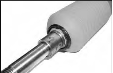
27. Use a Moly wheel bearing grease to lube the thick, small diameter O-ring and slip it onto the strut shaft. It will sit on top of the dust boot.
28. Place your 2-1/2” diameter Coil-Over Spring onto the Lower Spring Perch. Position the Lower Spring Perch so the top of the spring is below the top of the largediameter portion of the strut shaft. That will keep the spring from interfering with the installation of the Upper Spring Perch Assembly.
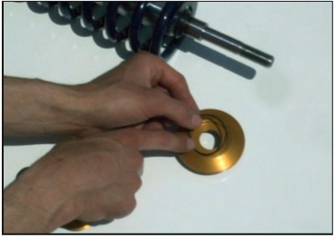
29. Grease the thin, large diameter O-ring and place it into the O-ring groove machined on the top side of the Upper Spring Perch.
30. Place one Needle Bearing Race into the recess on the top side of the Upper Spring Perch. Completely pack the Thrust Needle Bearing with a high quality Moly wheel bearing grease. Place the Thrust Needle Bearing on top of the installed Needle Bearing Race. Place the second Needle Bearing Race on top of the Thrust Needle Bearing.
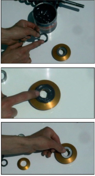
31. Grease the bottom of the Thrust Cone where it will contact the thin, large diameter O-ring from Step 29. Set the Thrust Cone onto the top of the Upper Spring Perch.
32. Slip the completed Upper Spring Perch Assembly over the top of the strut shaft. It will slide down and the Upper Spring Perch will sit on the thick, small diameter O-ring from Step 27.
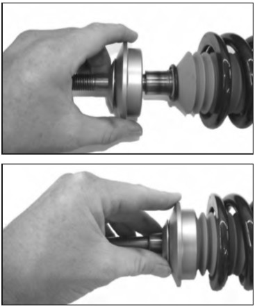
33. Slip the large 7/8” inside diameter Spacer Bushing over the strut shaft. It will sit down onto the Thrust Cone.
34. Place the 17mm inside diameter Thrust Washer over the top of the strut shaft. Do not be surprised if the Thrust Washer will not contact the shoulder of the shaft. The thick small diameter O-ring from Step 27 will be compressed and expanded during installation, and the Thrust Washer will then contact the shoulder of the strut shaft.
NOTE: Some companies’ C/C plates have a fixed-type spacer bushing pressed into the spherical bearing. With these types of C/C plates, skip Step 35, and you may not be able to maximize bump travel in Step 38.
35. Use the longest C/C plate spacer bushing (16mm inside diameter) that came with your C/C plates, and place it over the strut shaft. Slide it down until it sits on top of the Thrust Washer.
36. Place the strut shaft top into the spherical bearing of the C/C plate. Tighten the strut top retaining nut with enough spacers on top of the spherical bearing to prevent the nut from running out of threads on the strut shaft.
37. Slide the strut ears over the spindle ear, install both mounting bolts, and loosely thread on both nuts.
38. Loosely reattach the outer tie-rod to the steering arm on the spindle.
39. Check clearance between the Upper Spring Perch Assembly and the bottom of the C/C plate. The tightest spot will be toward the rearward bolt heads on the C/C plate bottom plates. Check clearance at full droop while the suspension is being steered. Jack the control arm up to ride height and check for clearance while the suspension is being steered.
Tip: Remember that the relative position of the Upper Spring Perch will change with different front end alignment settings. Be sure to allow clearance for any future caster/camber settings you may use. A small mirror will be necessary to check all clearances. (Spring and dust boot not shown for clarity)
40. The vertical position of the Upper Spring Perch Assembly is adjusted by using different combinations of Spacer Bushings. If needed, additional Spacer Bushings are included with the MM Coil-Over Conversion Kit. If the tightest clearance is less than 1/8”, use the next appropriate thicker Spacer Bushing (or combination of bushings) to gain necessary clearance. If clearance is in excess of 1/4”, use the next appropriate thinner Spacer Bushing (or combination of bushings) to position the Upper Spring Perch Assembly as high as possible for maximum bump travel.
41. After you have determined the proper combination of Spacer Bushings to place underneath the C/C plate, secure the strut shaft to the C/C plate with the strut top retaining nut. One Spacer Bushing is required on top of the spherical bearing, underneath the strut top retaining nut. Wait until the car is on the ground to torque the retaining nut.
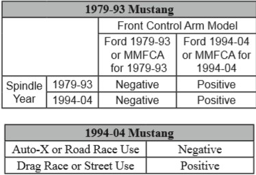
42. The Bilstein and MM struts have a larger bottom bolt hole in the strut-mounting ear to allow for production variations in the location of the holes in the spindles. This enlarged hole allows the spindle orientation, relative to the strut, to be changed by 1.4 degrees, before the bolts are tightened. This provides 1.4 degrees of camber adjustment at the strut to spindle interface. It is important to tighten this joint with the spindle held in either the maximum positive or maximum negative camber position on both sides of the car. This way, when you disassemble the front suspension in the future, it will not be necessary to realign the car after you reassemble it. Whether you choose the maximum negative or maximum positive position is a function of other suspension parts on you car. See the charts below for suggested spindle orientation settings.
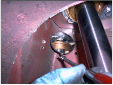
43) To position the spindle in the maximum negative position, pull straight up on the grease cap of the hub, while tightening the strut to spindles bolts.
To position the spindle in the maximum positive position, push straight down on the grease cap of the hub, while tightening the strut to spindles bolts.
Torque the strut to spindle bolts to 155ft-lbs.
44. Torque the outer tie-rod nut to factory specification and install a new cotter pin.
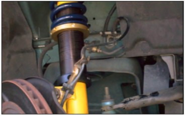
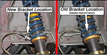
45. Do your first check for potential interference between the Coil-Over Spring, the Split Clamp Collar, and the brake hose where it attaches to the hard line. Use the jack to move the suspension from full droop to full bump, and check while someone moves the steering wheel back and forth. 1994-04 cars usually do not have any interference problems, but 1979-93 cars may require relocating the brake hard-line mounting bracket rearwards 1”. See the addendum at the end of these consumer instructions for more information.
NOTE: In rare cases there may be an interference between the Spring/Lower Spring Perch and the stock Kmember, near where the stock spring was located. To remedy that situation you will need a hand held grinder to clearance the K-member. After the installation is complete, with final ride height set, another check for interference between components must be made.
46. Adjust the height of the Lower Spring Perch. Raise it to a position where the Spring is just touching both the Upper Spring Perch and the Lower Spring Perch.
47. If the car has ABS, the mounting bracket for the sensor will need to be modified to clear the lower spring perch.
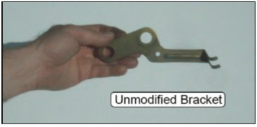
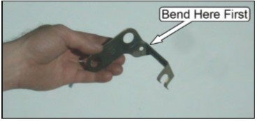
48. Use two sets of pliers to hold and bend the bracket forward near the base.
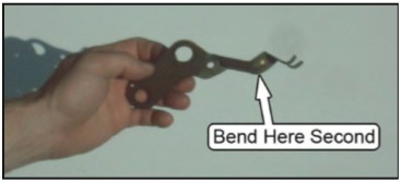
49. Then carefully bend it upward near the end where the wire attaches.
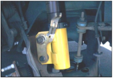
50. Reattach the mounting bracket to the spindle and adjust the bends if necessary to keep the mounting bracket close to the strut. Install and tighten the retaining nut for the mounting bracket.
51. Clean any dirt from the tip of the ABS sensor and reattach the ABS sensor to the spindle. Reattach the sensor’s wire to the mounting bracket.
52. Reattach the swaybar end-link to the control arm. Do not overtighten the end-link bushings.
53. If you removed the brake rotor, reinstall it now.
54. Reattach the brake caliper and torque the mounting bolts to factory specifications.
55. Slide the Adel Clamp onto the hose as shown.
56. The stack-up for the Adel Clamp hardware is shown below.
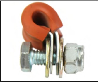
57. Place a washer under the head of the bolt and slide it through the Adel Clamp as shown.
58. Pass the bolt through the Brake Hose Tab, place a washer onto the bolt, and secure the bolt with the nylock nut.
59. Mount the tire and wheel. Check for clearance to the Coil-Over components. Remember that the final ride height has not yet been set, and so the position of the Lower Spring Perch may change.
60. Lower the car to the ground. Torque the lug nuts to factory specifications.
61. If using and adjustable strut, torque the strut shaft retaining nut to the strut manufacturers specification. Non-adjustable struts should have the strut shaft retaining nut torqued to the Ford specification.
62. Roll the car back and forth to settle the suspension.
63. Measure the ride height, as in Step 1. Adjust the ride height to match the previous measurement, or change the ride height as desired.
64. To change ride height, carefully jack the front of the car up and place it on jack stands. Hold the Threaded Sleeve with one hand, and use your other hand to rotate the Lower Spring Perch. In some instances it may be necessary to rotate the Lower Spring Perch with a Spanner Wrench (available separately as part number MMT-2).
65. After the ride height is set, tighten the set screw a little at a time until it takes some resistance to rotate the lower spring perch on the threaded sleeve. Only a very small amount of friction is needed to keep the lower spring perch from rotating. Any extra force on the set screw will result in damage to the Nylon tip and the threaded sleeve.
66. Have the front end professionally aligned. Remember that any time the ride height is changed, the camber and toe settings will have to be adjusted.
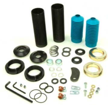
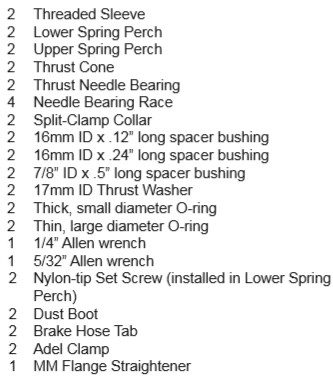
This kit includes the following:
This addendum is for 1979-93 Mustangs that have interference between the coil spring or lower spring perch and the brake line bracket, after installing the MMCO-1 or MMCO-2 front coil-over kits.
Follow the instructions below to relocate the bracket. Passenger side shown.
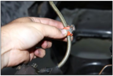
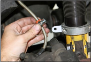
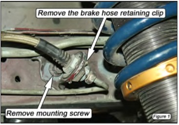
1. Remove the retaining clip that holds the brake hose in the brake line bracket. (Figure 1)
2. Remove the 8mm hex head size mounting screw retaining the brake line bracket to the frame rail.
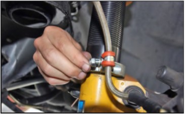
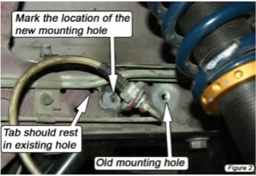
3. Slide the mounting tab rearwards approximately 1” until the small clocking tab is resting in the nearest existing hole in the frame rail. (Figure 2)
4. Mark the new screw location for the brake line bracket. (Figure 2)
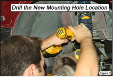
5. Move the brake line bracket out of the way and drill a 1/8” diameter hole on the mark made in Step 4. (Figure 3)
6. Reattach the brake line mounting bracket to the frame rail in its new location and tighten the mounting screw.
7. Reinstall the brake hose retaining clip. NOTE: The brake lines may need to be adjusted slightly to accommodate the new position of the brake line bracket. The lines can be easily bent the small amount needed by hand; no tubing bender is necessary.
8. Repeat Steps 1-7 for the driver side bracket.
