FREE 1 to 3-Day Delivery on Orders $149+ Details
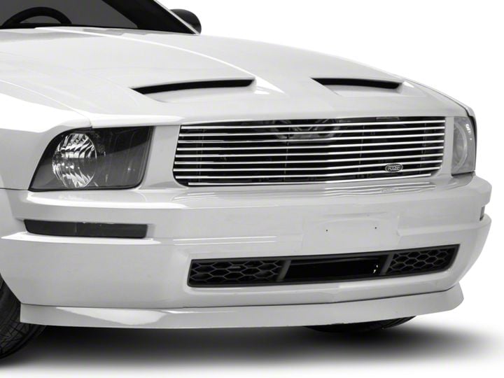
How to Install MMD by FOOSE Billet Upper Replacement Grille - Polished on your Mustang
Installation Time
30 minutes
Tools Required
- Phillips Head Screwdriver
- Flat Head Screwdriver
Shop Parts in this Guide
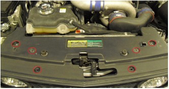
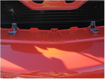
Step 1: Remove the 6 plastic retaining clips holding the upper plastic radiator cover to the radiator support and remove it from the vehicle.
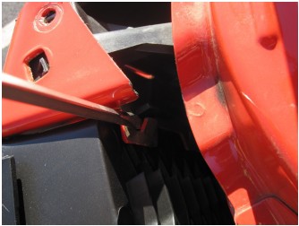
Step 2: Remove the grille by prying gently on the bumper cover tabs holding the grille and pulling outwards as shown.
Step 3: Install the U‐Clips on the taller side of each UBracket. Place the shorter two of the supplied U‐Brackets through the upper grille tab on each side as shown. Secure using the provided screws and holding tabs. Once secure, install another U‐Clip on the shorter side of each bracket as shown.
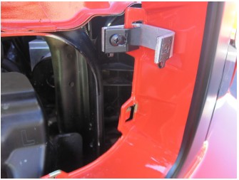
Step 4: Place the longer two of the supplied U‐Brackets through the lower grille tabs as shown. Secure using the provided screws and holding tabs. Once secure, install another U‐Clip on the shorter side of each bracket as shown.
Step 5: Once all four U‐Brackets are secure, place the billet grille in the grille opening making sure to align the holes in the grille with the U‐Clips on the brackets.
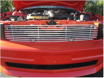
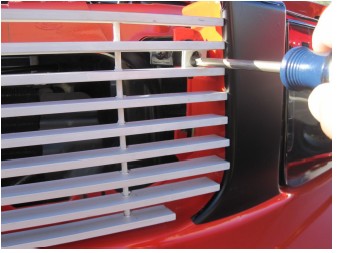
Step 6: Use the supplied screws to secure the billet grille to the brackets as shown.
Step 7: Re‐install the radiator cover removed in Step 1 to complete the installation.