FREE 1 to 3-Day Delivery on Orders $149+ Details
How to Install Maximum Motorsports K-Member Brace for Modular Engine & Hellion Turbo (79-95 All) on your Ford Mustang
Installation Time
1 hours
Tools Required
- 2 large C-clamps
- 4 jack stands
- Bumpsteer gauge
- Engine hoist or support truss
- Floor jack
- Masking Tape & Pen
- Plumb bob(s)
- Spring compressor (internal type)
- Tape measure
- Torque wrench
- T-55 Torx Socket
- Typical selection of hand tools

Shop Parts in this Guide
Read all instructions before beginning work. Following instructions in the proper sequence will ensure the best and easiest installation.
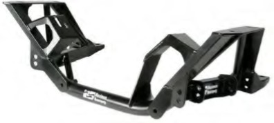
Thank you for purchasing the Maximum Motorsports K-member. The MM K-member is designed to maximize the performance of your Mustang’s front suspension. You will find many features that set our K-member apart from the rest.
• There are two sets of control arm mounting holes—that means the roll center height and camber curves can be optimized for your car’s ride height.
• The Ackerman steering geometry is adjustable and optimized.
• The wheelbase is lengthened by 0.75". Front to rear weight distribution is improved by 1%. Caster is increased by 2 degrees for improved cornering grip, tire wear, and high speed stability.
• The MM K-Member maintains the stock percentage of anti-dive geometry. Our testing has proven that increased anti-dive will hurt the car’s ability to absorb bumps during braking. Any less anti-dive will cause excessive pitching during braking.
• The K-member is the load path into the chassis for all front wheel steering, cornering and braking forces—it must be engineered for strength and stiffness. This is a fully triangulated design, using round or rectangular tubing where each is appropriate, and shear planes where necessary. This robust design is intended to last the life of your vehicle and provide maximum return on your investment.
• The MM K-Member provides increased clearance for engine and suspension service, and over 1” greater header clearance in critical areas. This provides much needed access to header bolts.
Proper installation of the MM K-member will require the use of the following parts:
• Tubular front control arms.
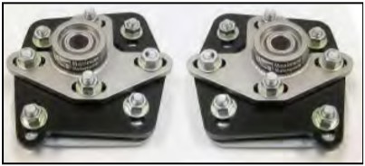
• Caster/Camber plates.
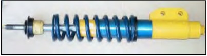
• Front Coil-Over conversion kit.
• MMST-6 Spherical Rack Bushings.
• Adjustable Tie-Rod ends.
• MM Relocation Kit for the front Swaybar, when using the MM forward-offset control arms.
We recommend the following parts to accompany the installation of a K-member:
• Solid steering shaft
• Shorter aftermarket urethane swaybar end links
• MM Front Sway Bar Bracket reinforcements (1979-93 cars)
• MM Strut Tower Brace
• High performance struts to match your spring rate
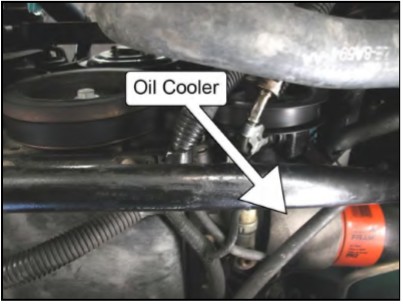
Modular Engine Oil Filter Relocation
4V Cobra engines and 1996-’98 GT engines equipped with automatic transmissions are typically equipped with a large oil cooler under the oil filter. Occasionally engines outside this category will have an oil cooler as well. Engines with an oil cooler require installation of an oil filter relocation kit (MMOC-3 or MMOC-4). Relocation of the oil filter provides required clearance for the MM K-member.
Bumpsteer and Rack Bushings
Installation of the MM K-member requires the use of an adjustable tie-rod kit (MMTR-1 or MMTR-3). This kit relocates the outer tie-rod end pivots in order to minimize bumpsteer with the revised front suspension geometry of the MM K-member.
MM requires the use of the MMST-6 Spherical Rack Bushings to position the rack as high as possible. This minimizes the offset of the tie-rod end below the steering arm of the spindle.
Spindle Compatibility
For best results, we recommend the 1996 Mustang spindles in all applications. This will result in the lightest, stiffest steering setup for minimum wandering and maximum responsiveness. The reason is because the steering arm on the 1987-95 spindles is located higher than on the 1996 spindles; therefore the 1987-95 spindles require an additional 1” of bumpsteer spacer between the steering arm and the tie-rod end than the 96 spindles.
Swaybar Location
If you use the MM Zero-offset or Reverse-offset front control arms, the front swaybar can remain mounted in the stock location. If you use the MM front control arms which have the ¾” forward-offset, the front swaybar must be mounted with the MM Relocation Kit for the Front Swaybar (MMFSB-50 or -51). The relocation kit moves the swaybar forward 3/4” to compensate for the more forward location of the swaybar mounting hole with the forward-offset control arms.
Stock K-member Removal
1. Disconnect the ground terminal at the battery.
2. Start with the vehicle on a flat, level surface.
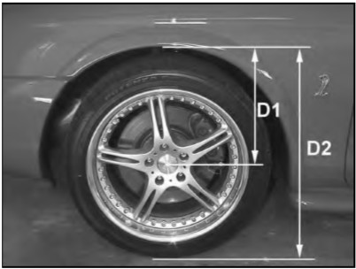
3. Measure the distance from the center of the front wheel to the fender lip. Record this dimension as D1. Also measure from the ground to the front fender lip. Record this dimension as D2. These dimensions will be need later.
4. Jack up the car and place it safely on four jack stands as high as possible. Two stands should be placed under the front subframe, just behind the radiator as shown. The other two stands should be placed under the rear axle.
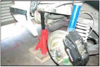
5. Level the car by measuring from the bottom of the rocker panels to the ground. Adjust the height of the jackstands to get the car as level as possible.
6. If your car currently has the 5.0 engine, It is best to remove it now and skip to Step 9.
7. If you already have a modular engine in place by whatever means, the engine needs to be supported from above. There are two ways of accomplishing this. One is to use an engine hoist. The second is to use an engine support truss. The second option makes the job much easier because there will be more room under the car.
8. This engine support truss lays across the chassis just inboard of the fenders, and supports the engine by two accessory bolts. (SN95 chassis shown)
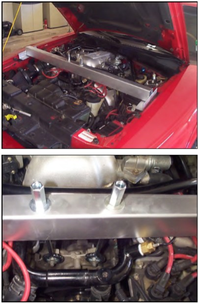
9. Remove the front wheels.
10. Remove the front caliper and hang it securely. Do not let the caliper hang from the brake hoses as this can cause unseen damage to the hose. Steel braided hoses are especially susceptible to damage if the caliper is dropped or allowed to hang unsupported.
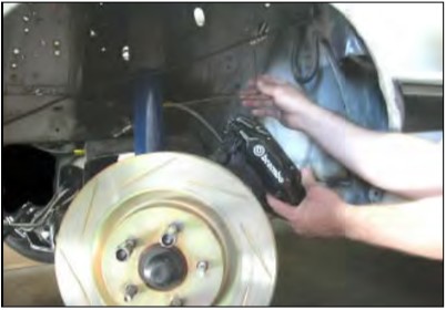
11. Remove the front brake rotor.
12. On 1994-95 cars, detach the ABS sensor from the spindle.
13. Loosen the front strut-to-spindle bolts, but do not remove them.
14. Loosen the tie-rod end nut but do not remove it.
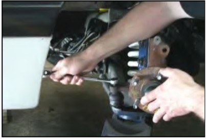
15. Spray the outer tie-rod end taper stud with penetrating oil.
16. Remove the front swaybar end link.
17. Turn the spindle to its maximum toe-in position. Place a floor jack under the control arm near the ball joint. Leave about ½” of clearance between the floor jack and the control arm.
18. Loosen the lower ball joint nut until the top of the nut is flush with the top of the ball joint stud.
19. Spray the ball joint taper with penetrating oil.
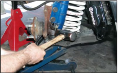
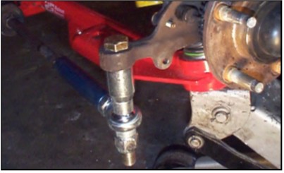
20. Free the tie-rod end by hitting the front end of the steering arm with a large hammer. Do this until the tie-rod end taper comes free from the steering arm.
21. Remove the nut from the tie-rod and detach the tierod end from the steering arm.
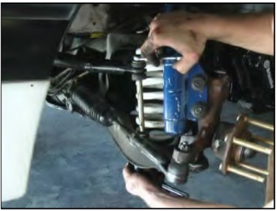
22. Strike the spindle just below the strut, where the ball joint attaches to the spindle, with a large hammer. Do this until the ball joint taper comes free from the spindle.
23. For cars equipped with conventional front coil springs, use an internally mounted coil spring compressor and compress the front coil spring. Most auto part and equipment rental stores rent this type of spring compressor.
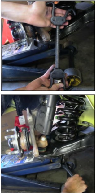
24. Raise the control arm 1/2” with the floor jack. Remove the ball joint nut completely.
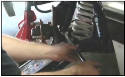
25. Remove the strut-to-spindle bolts completely.
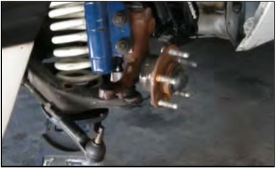
26. Remove the spindle.
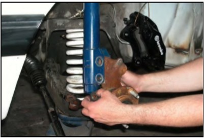
27. For easier access, remove the strut from the car.
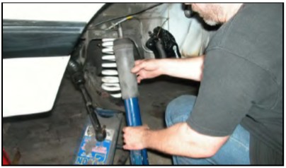
28. Carefully lower the floor jack until the front spring becomes unseated from the upper spring perch.
29. With the floor jack completely removed from under the control arm, release the internal spring compressor to free the spring from the control arm.
30. Repeat Steps 10-29 for the opposite side of the car.
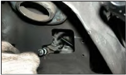
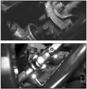
31. Remove the pinch bolt that holds the steering shaft to the input shaft of the steering rack. Some factory K-members have a hole which allows easier access to the pinch bolt.
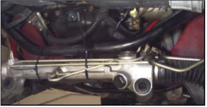
32. Remove the two bolts that hold the steering rack to the K-member. Pull the steering rack forward until it is just below the swaybar. To keep the steering rack out of the way, zip tie or wire it underneath the swaybar.
It is not necessary to disconnect any hoses from the steering rack.
33. If the engine is still in place, remove each of the retaining nuts holding the two motor mounts to the K-member.
34. If the engine is still in place, raise the engine about ½” with the engine hoist or the engine support truss. Raise the engine just far enough that the motor mounts do not touch the K-member. Disconnect any wires that may be attached to the K-member.
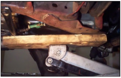
35. Place a wood board on the jack and raise the jack until the K-member is just supported on the wood board.
36. Loosen, but do not remove the four bolts that hold the K-member to the frame near the upper spring perches.
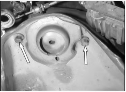
37. Remove the four bolts at the rear of the K-member.
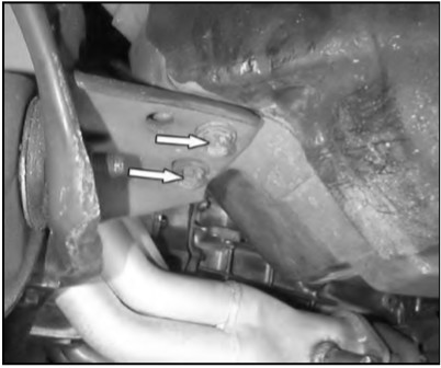
38. Remove the four bolts near the spring pockets completely. Have a second person stabilize the K-member while doing this. Slowly lower the floor jack and K-member while also checking for any objects that may hang up on the K-member. Lower the K-member to the floor and remove it from underneath the car.
MM K-member Installation
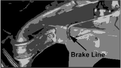
39. Raise the K-member into position underneath the front of the vehicle. Check to make sure that nothing is getting pinched as you raise the K-member. There may be brake line interference on one or both sides of the car. The lines may be carefully bent as needed, to provide required clearance. If necessary, trim the plastic fender liner.
40. Once the K-member is high enough, nstall all eight bolts that hold the K-member to the chassis. Note that the each of the two pairs of rearward bolts thread into
nuts nuts captured by a single removable nut plate.
41. Tighten the four upper bolts above the control arm mounting holes until the K-member is seated firmly against the frame rails. Do not tighten the four rearward bolts.
Squaring the K-member
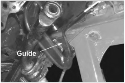
It is necessary to adjust the position of the K-member so it is square in the vehicle. This is accomplished with the aid of a plumb bob (two plumb bobs makes the job much easier), two C-clamps, a tape measure, a pen, and the two supplied angle iron guides.
NOTE: You must square the MM K-member to the rear suspension pick-up points. To do so, the rear control arm to chassis bolts must installed in Ford’s original orientation. Ford installs the bolts through the chassis from the inboard side of the frame rail with the threaded end toward the outside of the chassis. Check the orientation of these bolts. If necessary, reverse their orientation.
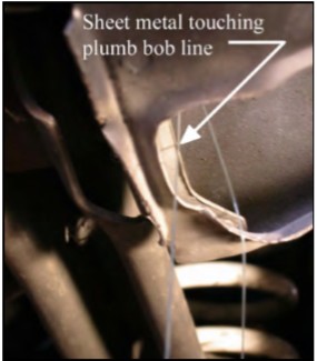
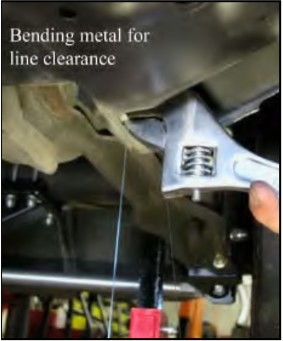
42. Wrap the plumb bob line ½ turn around the front (chassis end) mounting bolt of the rear lower control arm. This bolt can be accessed through the hole in the torque box just in front of the rear tire. The line should be over the threads of the bolt, all the way against the nut face. Hang the plumb bobs in the exact same manner on both sides of the car. For example, make sure the line is hanging off the bolt from the forward side or rearward side on both sides of the car. Make sure that the line hangs down from the bolt without touching any bodywork. If it does touch the chassis, bend the interfering metal out of the way.
43. Adjust the height of the plumb bob until it is very close to touching the ground. Tie a large weight to the free end of the line as an anchor, or secure the line by taping it to the chassis.
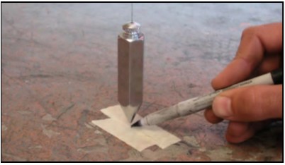
44. Stick pieces of masking tape to the ground directly under the tip of each plumb bob.
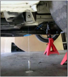
45. Wait for the plumb bob to stop swinging. Mark the position of each plumb bob by placing a small dot on the tape directly under the tip of the plumb bob.
46. Remove the plumb bobs.
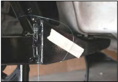
47. Go to the front of the car. Pass the plumb bob line through the very small hole located below the most rearward, lower mounting hole for the front control arm. Pass the plumb bob line through from front to rear.
48. Adjust the height of the plumb bob until it is very close to touching the ground. Make sure the line is centered at the lowest point of the hole. Place a piece of masking tape on the back side of the control arm tab on the K-member to fix the height of the plumb bob.
49. Stick pieces of masking tape to the ground directly under the tip of each plumb bob.
50. Wait for the plumb bob to stop swinging. Mark the position of each plumb bob by placing a small dot on the tape directly under the tip of the plumb bob. The measurements done in the following steps will require two people.
51. Measure the distance between the two dots on the ground on the left side of the car.
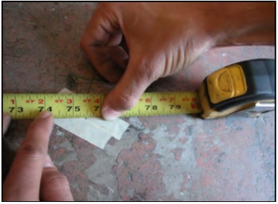
52. Take the same measurement between the two dots on the right side of the car.
53. These two distances should be the same. If the distances are not equal, on the side of the car with the shorter distance, loosen the two upper K-member mounting bolts. On the side of the car with the longer distance loosen only the rear upper K-member mounting bolt.
54. Using a rubber mallet or a pry bar, move the K-member on the shorter side forward enough to equalize the distances on both sides of the car. Snug the upper four K-member mounting bolts.
55. Make new dots on the ground to mark the new position of each of the front plumb bobs.
56. Re-measure the distances between the dots on both sides of the car and compare them.
57. Repeat this procedure until the distances match each other within 1/16”.
58. If you are unable to move one side of the K-member forward enough, you may have to move the opposite side rearwards.
59. If you think you may have disturbed the car on the jack stands, place the plumb bobs back onto the rear control arm mounting bolts and check that the dots on the masking tape are still indicating the correct position of the rear plumb bobs.
60. Once the wheelbase on each side of the car is equal, the next step uses the supplied angle iron guides. On each side of the car, clamp one angle iron guide underneath the frame rail directly in front of, and touching, the K-member. Use a C-clamp or large vise grips. The angle iron guides form stops to keep the K-member aligned front-to-rear while centering the K-member side-to-side in the following steps.
61. Measure the diagonal distances between the four dots on the ground. Record the distance from the dot on the front driver side of the car to the dot on the rear passenger side of the car as D3. Record the distance from the dot on the front passenger side of the car to the dot on the rear driver side of the car as D4.
62. If D4 is greater than D3, the K-member needs to be moved towards the driver side the car. If D4 is less than D3, the K-member needs to be moved towards the passenger side of the car.
63. Scribe a line in the fore/aft direction on the angle iron guide on one side of the car. Extend this line rearwards straight onto the bottom of the K-member flange (the flat plate which bolts to the chassis). This will be used as a reference to determine how far you have moved the K-member.
64. Loosen the four bolts holding the K-member to the frame. Tap the K-member from the side until it has moved the appropriate distance. This is easiest done with a large dead-blow hammer.
65. Tighten the 4 bolts, mark new dots with the plumb bobs and re-measure distances D3 and D4.
66. Repeat these Steps until the difference between D4 and D3 is 1/8” or less. This means the K-member is centered left to right under the car.
67. Once the K-member is properly positioned, place the plumb bobs back onto the rear control arm mounting bolts and check that the dots on the masking tape are still indicating the correct position of the plumb bobs. If not, this indicates that the car has shifted on the jack stands. If it has shifted, you will have to go through the squaring procedure again.
68. Torque the four upper K-member bolts to 89 ft/lbs.
69. Torque the four rearward bolts holding the K-member to the chassis to 72 ft-lbs.
70. Remove the C-clamps and angle iron guides.
71. Gently lower the engine down onto the K-member, making sure not to pinch any lines or wires. Watch header clearance to avoid denting a header tube. Install the engine mount nuts onto the engine mount studs and torque to 95 ft-lbs.
72. Remove the engine hoist.
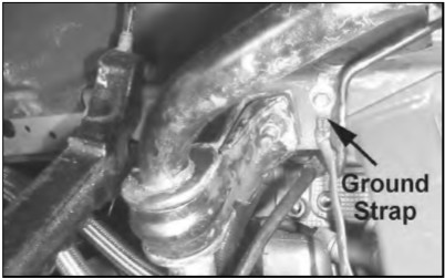
73. Drill a 1/8” hole in the driver side frame rail just forward of the K-member and reattach the ground strap.
Control Arm Location
The MM K-member has two sets of mounting holes for the front control arms. The lower set is raised 1 inch from the stock location. These holes should be used for all street driven vehicles. The upper set of holes is raised 2 inches from the stock location and is intended for race vehicles that have increased the amount of rear bump travel from stock.
Control Arm Assembly
See the instructions which came with your MM Front Control Arms.
Control Arm Installation
All MM K-members built after 3/11/2008 include a set of our MMF-2 Low Profile Front Conrtol Arm Bolts that are intended to be used on the forward pivots of the front control arms. Please follow the directions carefully to ensure proper installation.
74. Grease all exposed faces of the front control arm bushings using Prothane’s Super Grease supplied with your MM Front Control Arms.
75. Slide the control arm into place on the K-member with the sway bar mount facing toward the front of the car.
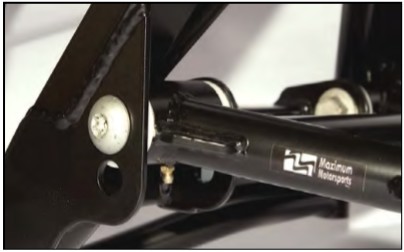
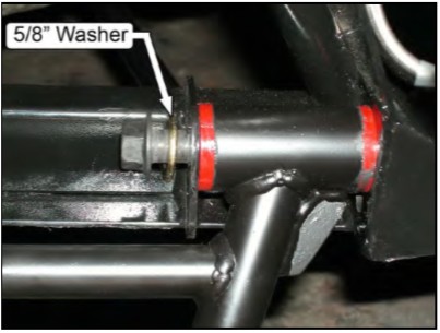
76. Install one of the provided MM Low Profile Front Control Arm Bolts into the forward pivot of each control arm. Install the stock pivot bolts into the rearward pivots using a supplied 5/8” washer under the head. The washer prevents the rearward bolts from bottoming out before the nut is fully tightened.
NOTE: The MM K-member requires all pivot bolts to be installed with the bolt heads toward the front of the car.
77. Thread a factory nut onto each pivot bolt.
78. Hold the head of the MM Low Profile Front Control Arm Bolt stationary using a T-55 Torx socket and tighten the nut. Torque the nut to 148 ft-lbs.
NOTE: The MM Low Profile Front Control Arm Bolts require holding the head of the bolt in place with a T-55 Torx socket while tightening the nut. Do NOT turn the Torx head to tighten. Instead, hold the bolt still with the T-55 socket and turn the nut to tighten.
NOTE: If you are NOT using MM Front Control Arms, consult the manufacturer of your control arms for their recommended control arm pivot bolt torque. The crush tubes of other brands’ front control arms may not be capable of withstanding the factory specification of 148 ft-lbs of torque. We do not endorse torquing the pivot bolts less than 148 ft-lbs.
79. Torque the remaining MM Low Profile Front Control Arm Bolt using the same procedure described above.
80. Torque the rearward, stock control arm pivot bolts to 148 ft-lbs.
Steering Rack Installation
The MM K-member is specifically designed to use the MMST-6 Aluminum Spherical Rack Bushings. Use of other rack bushings may not yield optimum Ackerman steering geometry and may cause the steering to bind.
Also, versions of the MM K-members prior to 3/11/2008 did not include the MMF-2 Low Profile Front Control Arm Bolts. If you do not have these bolts, we highly recommend contacting Maximum Motorsports and ordering a set.
81. The MMST-6 Aluminum Spherical Rack Bushings must be in place on the steering rack prior to the next Step. See the newest instructions (3/11/2008 or newer) that came with the MMST-6 bushings to install them into the rack. The MMST-6 bushings allow for three different rack offsets. In all cases, we recommend using the largest offset possible to position the rack as high as possible. This will minimize the height of the spacer stack under the spindle’s steering arm.
82. Untie the steering rack from the swaybar. Raise the steering rack into position while engaging the steering shaft onto the steering rack input shaft. The stock steering shaft will only engage onto the rack’s input shaft in one orientation. Be sure the steering shaft is fully engaged on the splines of the input shaft. On 1993 and earlier cars, the steering column may need to be extended slightly out of the firewall for this. To extend the steering column, grab the exposed portion of the column (where the steering shaft attaches to it) with Vise-Grip pliers, and pull it towards the front of the car. Pull on the inner rotating portion of the column, not the outer fixed portion. On 1994-95 cars, the steering shaft itself includes the collapsible portion, rather than the steering column. The steering shaft will extend slightly when pulled.
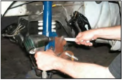
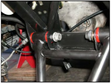
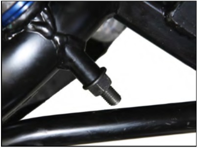
Unless previously trimmed, the stock steering rack bolts WILL interfere with the k-member handlebar brace. To eliminate this interference, the bolt must be shortened.
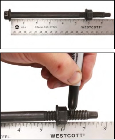
83. Screw one nut onto each rack bolt as far as they will go with a wrench. Using a ruler, mark both bolts 6.25” from the underside of the bolt head.
NOTE: The nut will have a lot of resistance, be sure to thread the nut on far enough to provide clearance for your cutting tool.
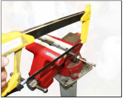
84. Use a hack saw or grinder to cut each bolt at the mark placed in Step 83.
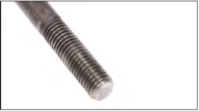
85. You will need to chamfer the edges of the cut bolts and clean the threads with a file so the OEM Ford nuts will easily start to thread onto the bolts. The bolt thread is M12 x 1.75. If you have a thread file or a die set, this can be used to clean up the threads after a chamfer has been put on the end with a file. After the bolt tips are dressed, remove the nuts as the final Step to ensure the threads are properly formed.
NOTE: The top of the nut is slightly deformed to act as a locking feature. Thus, the nut will not fully thread onto the bolt by hand as some resistance is normal.
86. Reinstall the trimmed steering rack bolts, from the front of the k-member.
NOTE: Be sure that the steering rack bolt is passing through the same offset hole in each rack bushing as determined using the latest MMST-6 installation instructions.
87. Install the factory nuts onto the steering rack bolts.
88. Snug the factory nuts onto the steering rack bolts. With offset steering rack bushings, ensure that the bushings as well as the spacers behind the rack are oriented correctly. The three holes in each bushing should be in a vertical line with the center of the bushing.
NOTE: The housing on some aftermarket manual steering racks may interfere with the driver side motor mount, depending on the height that the rack is positioned using the offset rack bushings. If this is the case, contact Maximum Motorsports for an optional spacer kit to move the rack forward.
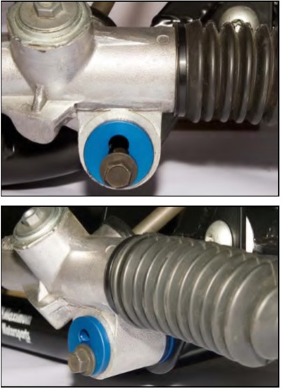
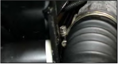
89. Check the orientation of the clamps which secure the rubber rack bellows boots to the rack housing. If the clamp bolt is installed towards the K-member as shown below, the clamp bolt may prevent the steering rack from being fully seated against the K-member. If necessary, rotate the position of the boot clamps.
90. Torque the steering rack mounting bolts to 55 ft-lbs.
91. Reinstall the steering shaft pinch bolt.
92. If you are using the stock steering shaft, torque the steering shaft pinch bolt to 25 ft-lbs. If you are using an aftermarket steering shaft, torque the steering shaft pinch bolt or set screws according to the steering shaft manufacturer’s instructions.
93. If using the forward-offset MM control arms, now is the time to move the swaybar forward 1” with the appropriate MM Relocation Kit (MMFSB-50,-51).
94. An adjustable outer tie-rod end style bump steer correction kit must be installed prior to the next Step. We recommend a bolt-through spindle style such as MM part number MMTR-1 or MMTR-3. The tapered stud type of kit will not have enough range of adjustment to correctly adjust bumpsteer with the geometry of the MM K-member.
95.We recommend installing MM caster/camber plates now if the car is not yet so equipped.
96. Prepare the front struts with a coil-over conversion kit now if the car is not yet so equipped.
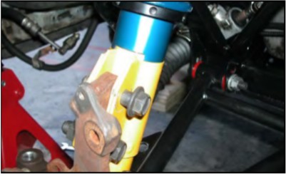
97. Place the floor jack under the control arm, and support it at a comfortable working height. Install the spindle onto the balljoint. Thread the nut on a few turns.
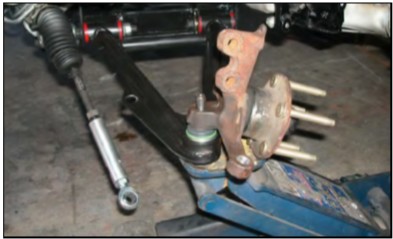
98. Install the coil-over strut assembly into place in the caster/camber plate. Adjust the spacers between the upper spring perch and the caster/camber plate as per the MM Front Coil-over Kit instructions to allow for maximum bump travel.
99. Raise the floor jack to align the spindle to the strut. Install the strut bolts from the rearward side.
100. Attach the adjustable outer tie-rod end to the spindle. As a starting point, place a 2” stack-up of spacers between the spindle and the tie-rod end. Torque the tie rod end bolt through the spindle to the specification of your bump steer correction kit.
101. Torque the ball joint nuts to 129 ft-lbs.
102. Torque the spindle to strut bolts to 148 ft-lbs. Torque the strut top nut to the specification of your strut manufacturer.
103. Install the brake rotor. Install the brake caliper. Torque the caliper bolts to the factory specs for your caliper. Re-attach the ABS sensor, if equipped.
104. Repeat Steps 97-103 on the opposite side of the car.
Clearance
105. Place the floor jack under the control arm. Adjust the lower spring perch to its lowest possible position. Cycle the suspension through full bump and droop with the jack while turning the front wheels from lock to lock. Check for interference between any suspension components. Do this on each side of the car.
106. Reinstall the front wheels. Tighten the lug nuts.
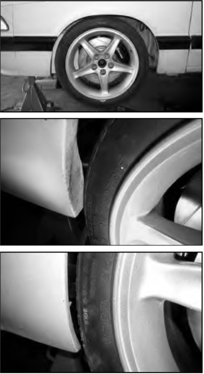
107. Depending upon the following parameters, there may be varying degrees of interference between the tire and the fender.
• Wheel size.
• Wheel offset .
• Tire size—be aware that the same nominal size tire from different manufacturers can have different actual sizes.
108. Again, place the floor jack under the control arm. Raise the control arm until the spindle is at your previous ride height. Use the dimension D1 you recorded in Step 3 to set the relationship between the spindle and the fender. Check for interference between the tire and the fender. Cycle the suspension through full bump and droop with the jack while turning the front wheels from lock to lock. Again check for interference between the tire and the fender. The inner fender lip may need to be rolled under for clearance. Also check for clearance between the tire and the front fender extensions. Be aware that the tire clearance may change after the front alignment is done.
109. In general, 1993 and earlier cars may have minor interference between the tire and the front fender extension while steering. This interference is minimal with the zero-offset control arms, and can easily be eliminated by trimming the fender extension.
110. With the forward-offset control arms, more extensive trimming of the fender extension is required, along with minor reworking or trimming of the fender’s sheet metal. A spreader bar may also be required to push the front portion of the fender further outwards from the chassis.
111. In general, 1994 and newer cars do not require any modifications when using the zero-offset control arms. Using the forward-offset control arms may require minor trimming of the plastic front bumper cover and front spoiler. This trimming is inside of the wheel well area, and is therefore very unobtrusive.
112. Thread the lower spring perch upwards until the spring is touching both the lower and the upper spring perches. Adjusting the spring perch so the spring is just starting to compress is a good starting point for adjusting ride height. Final ride height will be set after the car is back on the ground.
113. Remove the jack stands and set the car on the ground. Torque all your lug nuts to factory specifications. Roll the car back and forth to settle the suspension. Adjust the front ride height back to its original setting using the dimension D2 you recorded in Step 3. With the coil-overs you may also change the ride height to your liking.
114. With the ride height set check the position of the front control arms. If you have chosen the correct set of front control arm mounting holes the control arms will be close to being parallel to the ground. If not, you may want to either adjust the ride height or change to the other set of control arm mounting holes.
115. Do an approximate alignment of camber, caster and toe by eye. If camber or caster is changed significantly you may need to check tire clearance again by repeating the previous Steps.
116. Tighten the tie-rod end jam nuts. Check both the nut between the rod-end and the tie-rod end sleeve, as well as the nut between the rack and tie-rod end sleeve.
117. Reinstall the swaybar end links. It is likely that with the revised control arm geometry, you will need shorter end links. Rotate the sway bar until the forged end link hole is horizontal. Measure the distance between the sway bar end link hole and the swaybar end link hole in the front control arm. This is the ideal end link length. Use end links that are as close as possible to this dimension (19-408 to 19-417). Be careful not to over tighten and crush the endlink bushings.
118. Reconnect the battery ground cable.
Final Alignment
NOTE: The car’s behavior before correcting the alignment and bump steer will be very unstable. Driving the car before the alignment and bumpsteer is corrected is not recommended.
NOTE: Remember that the ride height must be set before doing the final alignment. Any time that the ride height is changed the camber and toe settings must be readjusted.
Caster Setting
Mustangs respond very favorably to increased positive caster. The greater the amount of positive caster, the greater the increase in negative camber for the more heavily loaded outside front tire.
Street-driven cars:
• Set caster to 5° to 6°
Race cars:
• Set caster to 6° to 8°.
It is typical for alignment shops to set the passenger side caster to a slightly greater amount than the driver side setting. For street-driven cars, a difference of 0.25° to 0.5° will help counter the effect of road crown, and prevent the car from pulling towards the right on most roads.
Unlike camber, there are many variables that affect the caster. For example, if the car has any rake, the measured amount of caster will be less than if the car was level. Changes in ride height will affect the measured amount of caster. Different technicians using different alignment equipment will indicate different caster values. Unlike camber, the number of degrees that caster is set to does not have to be exact. As long as caster is in the desired range, and the difference from one side to the other is not greater than 0.5°, it is fine.
Camber Setting
• Street-driven cars: 0.75° negative, /- 0.25°. Keep a close watch on tire wear patterns, and adjust camber to reduce poor wear, if necessary.
• Race cars: Depends greatly upon the track, driver, etc. Usually set around 3° negative as a starting point. Adjustments should be made after checking tire temperatures and wear patterns.
Toe Setting
Street-driven cars:
• We recommend setting the toe to the factory spec of 0.5° total toe-in for street use.
Race cars:
• Competition cars are typically set up with some amount of toe-out, for quicker turn-in response and increased front grip.
Remember that any time any change is made to the camber setting, the toe setting will be affected, and must be readjusted.
It is a good idea to always keep a record of the alignment settings. Inspect the tires frequently for uneven tread wear patterns. If uneven tire wear becomes evident, have the alignment adjusted. With a record of the previous alignment it will be easier to diagnose the problem and make alignment adjustments to improve tire wear.
Bumpsteer
The camber, caster and toe must be set before correcting bumpsteer. Adjust the car’s bumpsteer according to the copyrighted instructions you received with your MM Adjustable Tie-Rod End Kit.
Test drive and enjoy! Re-torque all bolts and nuts after 1000 miles