FREE 1 to 3-Day Delivery on Orders $149+ Details
How to Install Maximum Motorsports Rear Coil-Over Conversion Kit for Koni Shocks (79-04 All, Excluding 99-04 Cobra) on your Ford Mustang

Shop Parts in this Guide
Read all instructions before beginning work. Following instructions in the proper sequence will ensure the best and easiest installation.
NOTE: If you do not have a MM Panhard Bar you will need to purchase a second MM Lower Shock Mount. Please contact our sales staff.
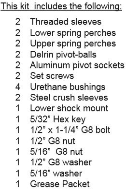
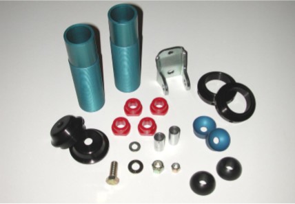
Thank you for purchasing Maximum Motorsports’ ultimate rear coil-over conversion kit. This kit is manufactured specifically for Koni double adjustable shock absorbers. There are many features you will find that set our coil-over kit apart from the rest. Starting at the top:
• We maximize bump travel by providing a Delrin pivot-ball and aluminum socket joint that does not reduce bump travel from that of a stock Mustang. Some of our competitor’s coil-over kits reduce bump travel by as much as 1-1/4”.
• The Delrin pivot ball and aluminum pivot socket also provide a smooth fluid motion that does not overstress the shock piston rod.
• Our upper spring perch assembly has been fully engineered for optimum strength, clearance, and bump travel -- it is shaped far better than any other.
• The lower spring perch is drilled for easy adjustment with a MM Spanner Wrench if pre-loading the spring is necessary. A set screw ensures that the lower spring perch will never move.
• The two-bolt mounting design of our lower shock mount provides a more rigid attachment to the axle. The higher loads of a coilover conversion on the original factory shock mount will distort and bend the bracket on the housing. In extreme cases, the single bolt of the factory shock mount has been known to break.
• While other companies simply anodize their aluminum parts for appearance, we have critical components hard anodized for maximum durability.
• Suspension loads are fed into the upper shoulder of the threaded sleeve, which provides a contact area able to support 4,000 lbs.
• The threaded sleeve is designed to attach securely to the shock absorber body without the need for circlip machining.
• Overlooked by other companies, our threaded sleeve assembly is designed to fit the shock absorber snugly. A tight fit keeps the threaded sleeve from rattling against the shock. More importantly, the lower spring perch is kept square to the shock, preventing the spring from arcing and rubbing on the threaded sleeve.
Finishing off the kit, we recommend using only topquality springs such as Hypercoil and Eibach. We back them with our extensive technical knowledge of rates, free lengths, and proper spring travel, all to ensure that your car will perform to its maximum potential.
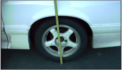
1. Measure the rear ride height of the car from the ground to the top of the wheel well opening. Record your reading, it will be needed later.
2 Loosen, but do not remove, the lug nuts on the rear wheels.
3. Block the front wheels and jack up the rear of the car. Once raised, support the rear of the car with jack stands under the subframes or torque boxes. With the shocks just short of full extension, support the axle housing on jack stands.
4. Remove the rear wheels.
5. Disconnect the rear sway bar from the control arms.
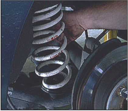
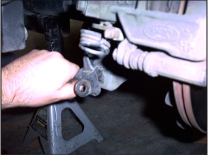
6. Support the rear lower control arm as close to the rear axle as possible with a floor jack. Remove the rear control arm axle pivot bolt and gradually relieve the spring tension by slowly lowering the jack until the spring is completely uncompressed and you can remove the spring by hand. With the spring removed, raise the control arm into place and reinsert the pivot bolt and torque to 111 lb-ft.
7. Repeat Step 6 with the opposite rear lower control arm, then reconnect the rear sway bar.
NOTE: You may also wish to install MM lightweight control arms that have no spring perches at this time.
8. From inside the car, remove the nut, thrust washer and upper rubber isolator from the top of each shock piston rod. Save these three components, as they will be reused later in the coil over installation.
NOTE: If you are installing new Koni shocks in place of your existing shocks, use the new nuts, thrust washers and isolators provided in the hardware kit, rather than the components that you removed in Step 8.
9. Remove the bottom shock bolts from the factory lower shock mounts (or the MM Panhard Bar Axle Mount) and remove the shocks from the car. Save the OEM 12mm lower shock mount bolts and nuts.
10. Remove and discard the lower rubber isolators, lower thrust washer, and plastic dust boots from each shock, as they will not be reused.
11. If you are using 1994-04 shocks, remove the bump stops from each shock (bumpstops are located on the shock shaft, under the dust boot). Save the bump stops; you will need them later. 1979-93 Mustangs do not use a bumpstop on the shock; the bumpstop was on the frame rail. NOTE: 1994-04 style bumpstops on the shock shaft perform better because they are softer and more progressive than the hard rubber bumpstop on the frame rails of 1979-93 cars. MM has a 1994-04 bumpstop (MM P/N SERVICE-5) to upgrade your 1979-93 Koni shocks. If you are using MM Service-5 on a 1979-93 Mustang, remove the rubber bump stops from the frame rails.
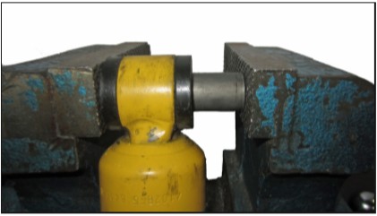
12. In a vise or press, remove the crush sleeve from each shock lower eyelet. Select a socket that is large enough to accept the crush sleeve into it’s center. Select a smaller deep socket that is small enough to push out the crush sleeve through the rubber. Discard the original Koni crush sleeves, as they will not be reused.
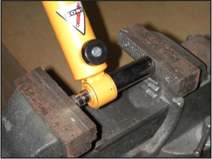
13. Use a similar process to remove the rubber bushings from each shock eyelet. Select a socket that is large enough to accept the rubber bushing into its center, but will still support the steel eye of the lower shock mount. Then select a smaller deep socket that will be able to push the rubber bushing out of the steel eye.
NOTE: It may help to cut the lip off of one side of the rubber bushing if you have trouble getting the socket to rest on the rim of the eyelet.
14. Remove and discard the factory lower shock mount from the passenger side of the axle.
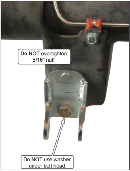
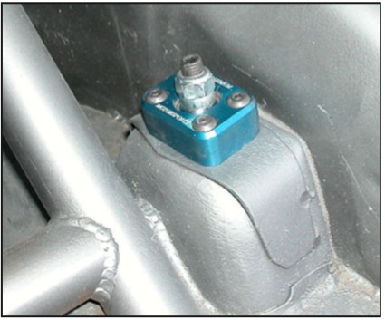
15. Install the MM lower shock mount onto the passenger side of the axle. Insert the 1/2” bolt (no washer) through the lower hole, with the bolt head facing the rear of the car. Next, place the 1/2” washer onto the bolt and thread on the 1/2” nut. Then place the 5/16” washer onto the stud and thread on the 5/16” nut. First torque the 1/2” bolt to 119 ft-lb. Next, torque the 5/16” bolt to 16 ft-lb.
NOTE: If the car does not have a MM Panhard Bar, you must purchase an additional lower shock mount (MMSM-2) from our sales staff and repeat Step 15 to install a MM lower shock mount on the driver’s side.
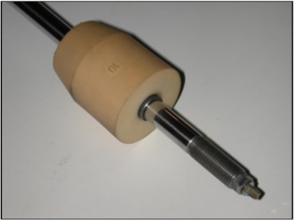
16. Thread the lower spring perch onto the threaded sleeve.
17. Install the threaded sleeve onto the shock absorber body by sliding the sleeve down from the top (piston rod) end of the shock, with the flanged lip of the sleeve towards the stud. Slide the sleeve downward until the lip of the threaded sleeve firmly contacts the upper portion of the shock body. Reinstall the bump stop shim so that it seats squarely against the top of the shock.
18. Lubricate two of the MM lower shock mount urethane bushings, inside and out, with the supplied grease. Completely coat the surfaces inside the shock eyelet with grease. Push the greased urethane bushings into the eyelet of the shock.
19. Liberally coat the outside of the supplied steel crush sleeve with the grease. Insert the crush sleeve into the urethane bushings. To do so, it will be necessary to use a vice or large set of pliers to press in the crush sleeve.
20. Place one of the coil springs onto the lower spring perch. Position the lower spring perch so that the top of the spring is well below the welded isolator bung on the shock piston rod, as this will make the installation of the remainder of the parts much easier.
21. Reinstall the Koni bump stop such that the top surface is approximately 1/8” below the top of the welded isolator bung.
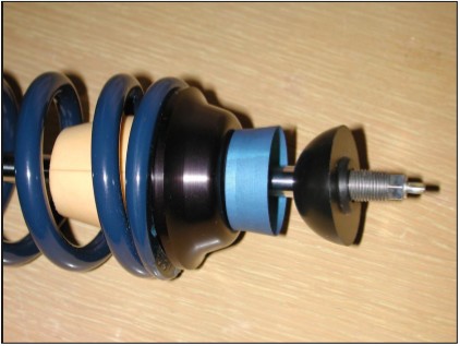
22. Place the upper spring perch over the piston rod and onto the spring.
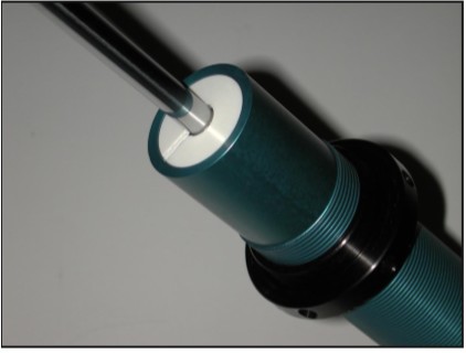
23. Place one of the aluminum pivot sockets over the piston rod (with the cup facing upward) until it seats against the welded isolator bung located near the top of the shock piston rod.
24. Completely coat the inside of the pivot socket with the supplied grease.
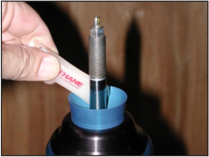
25. Place one of the Delrin pivot balls on the shock piston rod with the curved side facing down toward the aluminum pivot socket.
You have now completed one coil-over assembly. Repeat Steps 16 - 25 for the second shock absorber.
26. Starting on the passenger side of the car, position the shock piston rod of one of the completed coil-over assemblies through the hole in the shock tower.
27. Compress the shock absorber slightly and insert the OEM 12mm lower shock bolt through the lower shock mount and the shocks’ steel crush sleeve. Torque to 59 ft-lb.
28. Using a jack, raise the passenger side of the axle to seat the Delrin pivot-ball against the bottom side of the shock tower. Be sure to keep the Delrin pivot-ball centered in the mounting hole of the shock tower as the pivot-ball engages the bottom side of the shock tower.
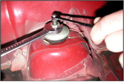
29. From inside the car, on top of the shock tower, place a KONI rubber isolator, steel thrust washer, and nut on top of the shock shaft. Using a 9mm wrench to keep the shock piston rod from spinning, tighten the nut until the thrust washer just begins to drag on the rubber isolator, and then tighten the nut by 4 more complete turns.
30. Raise the lower spring perch until the spring just contacts the upper and lower spring perches.
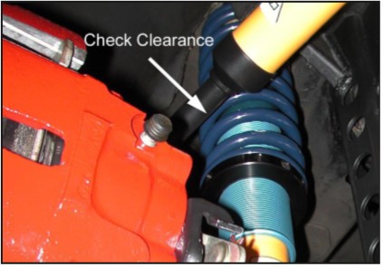
31. If your vehicle is equipped with quad shocks, verify that you have sufficient clearance between the outside of the coil over spring and the quad shock piston rod dust sleeve. You may increase the clearance slightly by placing a 12mm flat washer between the rear quad shock eye and the frame-mounted stud.
32. Repeat Steps 26 - 31 to install the completed coil-over assembly into the driver’s side of the car.
33. Reinstall the wheels and torque the lug nuts to factory specifications.
34. Remove the jack stands and lower the car.
35. Roll the car back and forth slightly to settle the suspension.
36. Measure the ride height as done in in Step 1. Compare to the dimension recorded in Step 1, and determine if the car needs to be raised or lowered to match that starting ride height. If a different ride height is desired, we suggest first adjusting to match the previous ride height, and then making further adjustments. Support the vehicle on jack stands to remove the weight from the springs, and adjust the spring perches. Hold the threaded sleeve with one hand and turn the lower spring perch with your other hand. (Up, to raise the car, and down, to lower the car)
NOTE: If you find that you need to preload the spring, use MM’s spanner wrench to help rotate the lower spring perch.
37. Lower the car and repeat Steps 35 and 36 until the desired ride height is achieved.
38. Once the ride height is correct, use the supplied 5/32” hex key to snug the nylon tipped set screw in the lower spring perch. This will hold the spring perch in the desired location.
NOTE: Do NOT overtighten the setscrew. It only needs to be tight enough to prevent the spring perch from rotating. Overtightening it can damage the perch, the threaded sleeve, and even the shock.
Available for your Rear Coil-over Kit
MMSM-5 Racing Rear Upper Shock Mount
This racing duty upper shock mount uses a spherical bearing (just like the MM Caster/Camber plates) to positively locate the upper end of the rear shock. It eliminates the last little bit of potential binding that may come from the rubber still used at the very top of the shock mount. The machined aluminum block sandwiches the rear shock tower with a doubler plate.