FREE 1 to 3-Day Delivery on Orders $149+ Details
How to Install Maximum Motorsports Road & Track High-Rate/Torque-Arm Rear Springs (79-04 All, Excluding 99-04 Cobra) on your Ford Mustang

Shop Parts in this Guide
- Maximum Motorsports Road and Track High-Rate/Torque-Arm Rear Springs (79-04 Mustang, Excluding 99-04 Cobra)
- Maximum Motorsports Road and Track Lowering Springs (94-95 Mustang Convertible)
- Maximum Motorsports Road and Track Lowering Springs (94-95 Mustang Coupe)
- Maximum Motorsports Road and Track Lowering Springs (96-98 Mustang Convertible; 99-04 Mustang GT Convertible)
- Maximum Motorsports Road and Track Lowering Springs (96-98 Mustang Coupe; 99-04 Mustang GT Coupe)
- Maximum Motorsports Road and Track Lowering Springs (83-93 Mustang Convertible)
- Maximum Motorsports Road and Track Lowering Springs (79-93 Mustang Coupe, Hatchback)
Read all instructions before beginning work. Following instructions in the proper sequence will ensure the best and easiest installation.
Maximum Motorsports’ Engineering Team worked with a major spring manufacturer to develop our new spring sets. These are top quality springs, made to our specifications.
The new MM Springs are designed to have less progression than other spring brands. The more linear nature of the MM Springs makes the amount of lowering more consistent, and the handling more predictable. Except for the Open-Track series, the MM Springs are intended to be suitable for a daily driven car, and as such we have designed the MM Springs with just the right blend of performance and ride quality. Knowledgeable performance enthusiasts know that lowering a car too much is a sure-fire way to destroy a car’s handling prowess, and therefore MM Springs are designed to avoid excessive lowering.
Note about Settling
It is a commonly held myth that all springs settle and become shorter after a period of time in the car. That is not true of high quality springs. Well-made springs do not “take a set.” However, spring isolators do settle over time. Urethane isolators have a much longer lifespan than the stock rubber spring isolators. If the initial ride height of your new springs isn’t consistent from side to side, or is higher than you anticipated, allow some driving time to let the isolators take their final shape.
Note about Lowering
The advertised lowering of the springs is based on best estimates for a stock-weight car. Any changes to the weight or weight distribution of the vehicle, such as adding aluminum cylinder heads (on 5.0L cars), a turbo or supercharger, removal of the back seats or interior, battery relocation, or other modifications that add or subtract weight, will alter the ride height of the car.
MM Recommends
When switching to stiffer springs, it may be necessary to upgrade your shocks and struts to maintain proper suspension damping. Please contact Maximum Motorsports if you have questions about your particular application. We offer a variety of shocks and struts, including Bilstein, Koni, Tokico, and custom valved MM Bilsteins.
If your car is not already equipped with MM Caster/ Camber plates, we recommend installing them with your new springs. In addition to allowing fast and easy adjustment of both caster and camber settings, the MM Caster/Camber Plates will also help restore the suspension travel lost whenever a car is lowered.
Front Spring Installation
Note: If you have MM Caster/Camber Plates installed on your vehicle, be sure to note the position of your strut shaft height as detailed in the MM Caster/ Camber Plate consumer instructions. When reinstalling the struts, set the strut shaft spacers as detailed in the MM Caster/Camber Plate consumer instructions to maintain correct bump and droop travel for the front suspension.
Safety Warning
Compressed springs contain a lot of potential energy. Be very careful to not inadvertently release a compressed spring. Serious injury and property damage may occur. If you are not confident with your expertise in swapping springs, consult a professional installer.
1. Loosen the top strut-retaining nut, but do not remove it. This can sometimes be more easily done before raising the car onto jackstands. Depending upon the design of the strut shaft, a hex key or very large screwdriver may be needed to prevent the shaft from turning with the nut. An air-powered impact wrench works even better. Also break loose the front lug nuts, but do not remove them.
2. Block the rear wheels, and jack up the front of the car and place it safely on jack stands. The car must be high enough that the front control arms can swing down, nearly vertical, for the front spring installation.
3. Remove both front wheels.
4. Work on one side of the car at a time.
5. Remove the front brake caliper and hang it securely. Do not let the caliper hang from the brake hose, as this can cause unseen damage to the hose. Steel braided hoses are especially susceptible to damage if the caliper is dropped or allowed to hang from the brake hose.
Front Caliper Removal for 1979-93 Cars:
• To remove the caliper, remove the bolts securing the brake caliper to the spindle.
Front Caliper Removal for 1994-04 Cars:
• Remove the caliper bolts securing the brake caliper to the anchor plate. Use a back-up wrench to prevent the guide-pins from spinning.
• If you are removing the brake rotor, you will need to remove the anchor plate where it attaches to the spindle.
6. Remove the front brake rotor, if desired. While not absolutely required, removal will make the control arm assembly lighter and much easier to handle. On 1979-93 cars, removal of the rotor will require wheel bearing adjustment during reassembly.
7. Detach the front swaybar end link from the front control arm.
8. Loosen the front strut to spindle bolts, but do not remove them.
9. Loosen the tie rod end nut, but do not remove it.
10. If the OEM rubber control arm pivot bushings are present, loosen the front control arm pivot bolts, but do not remove them. If urethane or Delrin control arm bushings are fitted, there is no need to loosen the pivot bolts.
11. Spray the outer tie-rod end’s tapered stud with penetrating oil.
12. Turn the steering wheel to full lock so that the tierod end is pointed out.
13. Free the tie-rod end from the spindle by hitting the front end of the steering arm with a large hammer. Be careful to not hit and damage the threads of the outer tie-rod end.
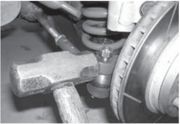
14. Remove the nut, and the tie-rod end from the steering arm.
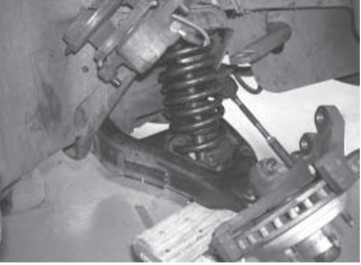
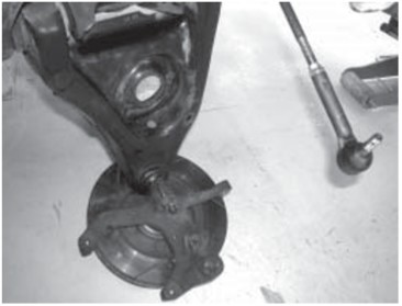
15. Use an internally mounted coil spring compressor and compress the front coil spring. Compress the spring onto the control arm by placing the bottom portion of the spring compressor underneath the control arm. Most auto part and equipment rental stores rent this type of spring compressor. Some experimentation may be required to find the best location for placement of the spring compressor.
16. Support the front control arm by placing a floor jack under it, as close to the ball joint as possible. Exert just enough upwards force with the jack to allow removal of the strut to spindle mounting bolts.
17. Remove the strut from the car.
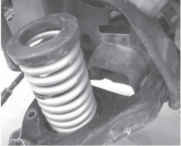
18. Carefully lower the floor jack until the front spring becomes unseated from the upper spring perch. Allow the control arm to hang free.
19. With the floor jack completely removed from under the control arm, carefully release the internal spring compressor to free the spring from the control arm. Do not stand in line with the spring, in case it unexpectedly comes loose from the compressor.
20. Install new spring isolators on the new front spring. Use factory replacement parts, or contact MM to upgrade to Urethane Spring Isolators. (Part number: 6-1703-BL)
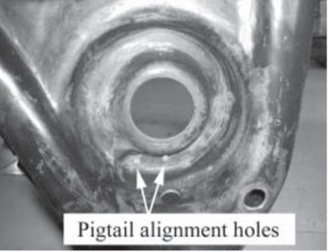
21. Set the spring in the lower seat on the control arm. To properly align the spring in the lower spring perch. Note that there are 2 holes near the end of the pocket on the control arm, spaced about 1 inch apart. The end of the spring should be placed between the two holes.
22. Compress the new front spring with the spring compressor, onto the front control arm.
23. Using a floor jack, raise the control arm up so that the spring is starting to seat in the upper perch. Make sure the upper spring isolator is in place. Note: The floor jack must be positioned to lift the control arm from directly underneath the ball joint. If the jack is positioned inboard of the ball joint, the leverage of the control arm will begin to lift the car off the stands before the spring is compressed enough to allow installation of the strut.
24. Continue raising the jack until the spring is fully seated in the upper perch, and the spring is compressed enough to allow reinstallation of the strut.
25. Re-install the strut. It is easier to install the strut by first placing it in the upper mount, threading on the top retaining nut, and then attaching the strut to the spindle.
Note: If using MM Caster/Camber Plates, be sure to adjust the strut spacer stack to accommodate the new ride height. Refer to your MM Caster/Camber Plate instructions.
26. Once the strut is attached to both its upper mount and the spindle, it is safe to remove the floor jack, as the spring cannot become dislodged.
27. Carefully release the spring compressor tension, and remove it from the spring.
28. Torque the strut mounting bolts at the spindle to 148 ft-lb.
29. Torque the strut shaft nut to 74 ft-lb. Some aftermarket struts, particularly adjustable ones, require a lower torque value. Over-tightening those may cause the strut shaft to break. Refer to your strut manufacturer’s torque recommendations.
30. Re-install the tie rod ends. Torque the tie rod studs to 41 ft-lb and install a new cotter pin. If an adjustable outer tie-rod end bumpsteer kit has been fitted, torque to the manufacturer’s instructions.
31. Reinstall the brake rotor if previously removed. If applicable, adjust the wheel bearings as per a shop manual.
32. Re-install the brake caliper to the spindle.
33. Torque the brake caliper mounting bolts. The stock calipers are torqued to the following specifications. For aftermarket calipers, consult the manufacturer’s instructions:
1979-93 Caliper to Spindle: 45-65 ft-lbs.
1994-04 Caliper to Anchor Plate: 23 ft-lb
1994-04 Anchor Plate to Spindle: 85 ft-lb
34. Repeat Steps 5 through 33 on the other side of the car.
35. Re-install the wheels and torque the lug nuts to the wheel manufacturer’s specifications.
Note for customers using stock rubber front control arm bushings
When rubber control arm bushings are still in use, the car must be at the new lower ride height when tightening the control arm pivot bolts. If the car is placed on ramps for ease of access, be sure that all 4 wheels are up on ramps of equal height. The best method is to have the car on a drive-on lift such as those found at a muffler shop. Failure to torque the bolts with the car at the new lower ride height will add undesirable pre-load to the rubber bushings. This will change the wheel rate of the suspension, increase ride harshness, and will cause the rubber bushings to wear out prematurely. Urethane and Delrin control arm bushings may have their pivot bolts tightened with the suspension at full droop, without any resulting damage or problems.
36. Torque the front control arm pivot bolts to 148 ftlb.
37. Reconnect the swaybar end links.
Note: After the spring installation, the car will have different static alignment because of geometry changes caused by the change in ride height. The camber should be adjusted. The toe setting must be adjusted. Have your car aligned by a professional alignment shop immediately.
Rear Spring Installation
38. Block the front wheels and jack up the rear of the car. Once raised, support the rear of the car with jack stands under the rear subframe or torque boxes.
39. With the shocks just short of full extension, support the axle housing on jack stands.
40. Remove the rear wheels
41. Remove the rear sway bar by removing the four bolts that attach it to the two rear lower control arms.
42. If the parking-brake cable is attached to the lower control arm, detach it and secure it safely out of the way so that it does not get caught on the control arm or spring during removal and installation.
43. If the OEM rubber control arm pivot bushings are present, loosen both of the rear lower control arm pivot bolts on each arm, but do not remove them. If the rear lower control arm bushings are urethane, Delrin, or spherical bearings, there is no need to loosen the pivot bolts at the chassis end of the lower control arms.
44. Support a rear lower control arm with a floor jack. Place the jack as close to the rear axle as possible. Remove the rear lower control arm axle-end pivot bolt. Carefully relieve the spring tension by slowly lowering the jack until the spring is completely uncompressed, and the spring can be removed.
Note: Complete the installation on one side before moving to the opposite side. Do NOT remove the axle-end pivot bolts for both rear lower control arms at the same time. Doing so will cause the axle to move out of position, and significantly more effort will be required to realign the holes for the axle-end pivot bolts.
45. Install new spring isolators on the new rear springs. Use factory replacement parts, or contact MM to upgrade to Urethane Spring Isolators. (Part number: 6-1701-BL)
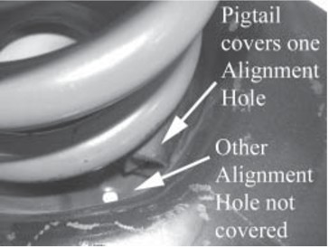
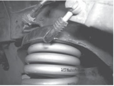
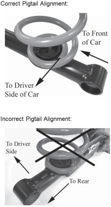
46. Install the new rear spring onto the control arm. Make sure the spring’s pigtail is properly oriented on the lower spring perch, pointing toward the driver side of the car. Note that both rear springs are identical, and the spring’s pigtail is oriented the same (pointing toward the driver side of the car) for both rear springs.
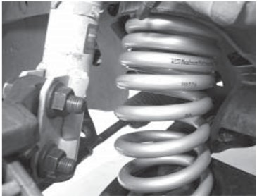
47. Raise the control arm into place with the floor jack. Reinsert the pivot bolt and thread on the nut, but do not tighten.
48. Repeat Steps 42 through 47 for the other control arm.
Note for customers using stock rubber rear control arm bushings
When rubber control arm bushings are still in use, the car must be at the new lower ride height when tightening the control arm pivot bolts. If the car is placed on ramps for ease of access, be sure that all 4 wheels are up on ramps of equal height. The best method is to have the car on a drive-on lift such as those found at a muffler shop. Failure to torque the bolts with the car at the new lower ride height will add undesirable pre-load to the rubber bushings. This will change the wheel rate of the suspension, increase ride harshness, and will cause the rubber bushings to wear out prematurely. Urethane, Delrin, and spherical bearing control arm bushings may have their pivot bolts tightened with the suspension at full droop, without any resulting damage or problems.
49. Torque the rear control arm pivot bolts to the following specifications.
1979-98: 86 ft-lb.
1999-04: 111 ft-lb.
50. On cars with stock, rubber-bushed rear upper control arms installed, loosen the Upper Control Arm mounting bolts to release bushing pre-load caused by the change in ride height. With the car at ride height, torque the chassis-end pivot bolts to 72 ft-lb and, the axle-end pivot bolts to 82 ft-lb for all 1979-04 Mustangs. This step is not necessary if the upper control arms are fitted with urethane bushings or spherical bearings.
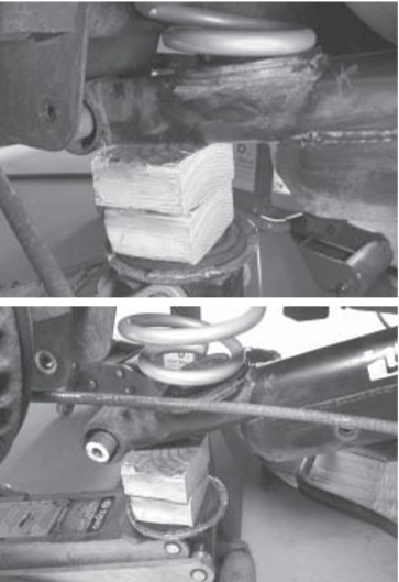
51. Install the supplied pinion snubber. (Part number: MMPS) Installation instructions are packaged with the new pinion snubber.
52. Re-install the rear swaybar. If you have an aftermarket swaybar, consult the manufacturer’s instructions for bolt torque. Torque the OEM swaybar mounting bolts to the following specifications:
1979-93: 31-51 ft-lb.
1994-98: 29-37 ft-lb.
1999-04: 41 ft-lb
53. Re-install the wheels on the car and torque the lug nuts to the wheel manufacturer’s specifications.
54. Safely lower the car to the ground.
55. Test drive the car and enjoy.
Post-Installation Notes
• New struts and shocks may cause the ride quality to feel slightly harsher upon initial installation. Newly installed springs are often blamed, when the culprit is actually the struts and shocks that were installed at the same time as the springs. Ride quality usually improves after a break-in period of a few weeks.
• Gas-charged struts and shocks tend to hold the car up slightly, and therefore affect the ride height.
• New spring isolators will settle over time. Do not be surprised if the ride height seems slightly different after a few days.
• When comparing ride height before and after installation of lowering springs, be consistent in taking measurements. For example, any variation in fuel load will affect ride height.
• All 1979-2004 Mustangs are essentially the same chassis, and therefore the springs themselves are interchangeable between most models and years. However, the same spring will affect ride height, ride quality, and handling characteristics differently when installed in different years and models because of differences in weight, the front-to-rear weight distribution, and the starting ride height.