 FREE 1 to 3-Day Delivery on Orders $149+ Details
How to Install Maximum Motorsports Road & Track Lowering Springs (05-14 Convertible) on your Ford Mustang
Installation Time
2 hours
Tools Required
- Spring compressor
- Standard assortment of hand tools
- Floor jack & three jack stands
- 1/2” torque wrench

Shop Parts in this Guide
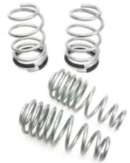
Maximum Motorsports high-performance springs are designed to improve your Mustang’s handling on the street, the open road, and the track. These aren’t just a lowering spring, but were designed primarily to improve handling without significantly degrading ride quality. Add our optional short progressive-rate bumpstops to help maintain good street manners for your lowered Mustang. On the road and the track, MM springs provide an excellent balance of handling and ride quality.
SAFETY WARNING
Compressed springs contain a lot of potential energy. Be very careful not to inadvertently release a compressed spring. Serious injury and property damage may occur. If you’re not confident with your expertise in removal and installation of springs, consult a professional installer.
Read all instructions before beginning work. Following instructions in the proper sequence will ensure the best and easiest installation.
Supplemental Installation Notes
• Alignment will be required after installation.
• We highly recommend installing MM’s caster/ camber plates when lowering your Mustang. They allow correct front tire alignment and camber adjustment.
• Our Mm5BSF-1 front and Mm5BSR-2 rear bumpstops will be very useful with your new springs. Its short height increases suspension travel, which is very beneficial for lowered Mustangs.
This Kit Contains
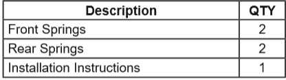
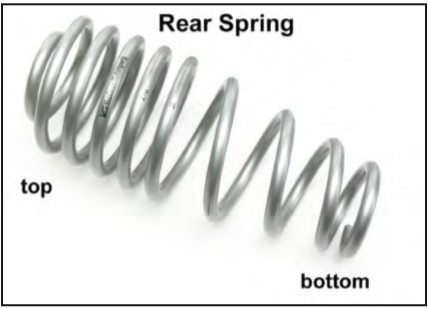
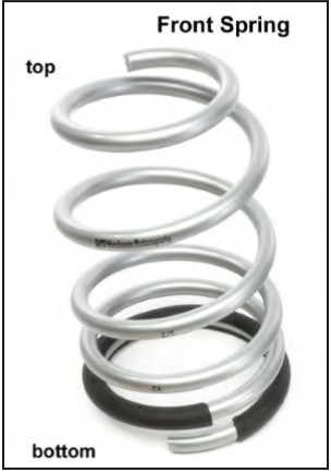
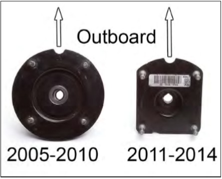
Component Identification
Installation
NOTE: We highly recommend replacing the strut-tospindle mounting hardware while installing this spring kit. Ford considers this hardware to be one-time use only. The new OEM hardware can be purchased from your local Ford dealer or Maximum Motorsports (Part# MMF-3). Four bolts W714652 S439 and four nuts W714653 S900 are required. Note that this is newly updated Ford hardware; it’s now fine-thread and requires a higher tightening torque. The new torque specification for this hardware is 225 Nm (166 lb-ft).
Front
1. Raise front of car and support it using jack stands.
NOTE: Vehicle must be lifted and supported under rocker panel pinch welds (as specified in Ford service manual) to avoid damaging chassis. Do not lift by K-member.
2. Remove front wheels.
3. Disconnect swaybar from both front struts.
NOTE: Work on one side of car at a time.
4. Loosen but don’t remove the four upper strut mount nuts.
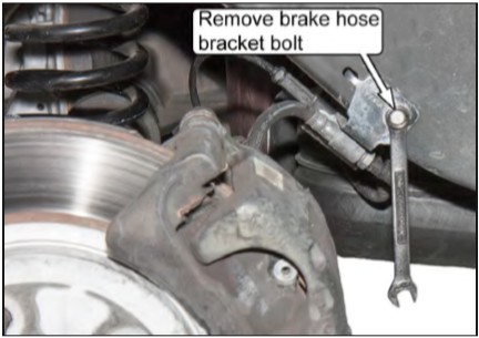
5. Remove brake hose bracket on back of strut.
6. Detach ABS sensor wire from strut.
7. If equipped, disconnect electrical control wire and connector from strut bottom.
8. Support bottom of control arm and spindle with a jack stand.
NOTE: Damage to OEM lower control arm bushings, tie-rods, or brake lines may occur if the control arm is unsupported and the spindle falls outward.
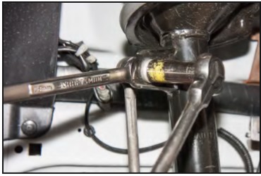
9. Remove the two spindle-to-strut bolts. 2011-14 vehicles have an interference fit between the bolts and the spindle. A hammer will be required to tap the bolts out.
10. Holding the strut securely, remove the four upper strut mount nuts, being careful not to drop the strut.
11. Remove the strut and spring assembly. Don’t snag it on any brake lines or sensor wires.
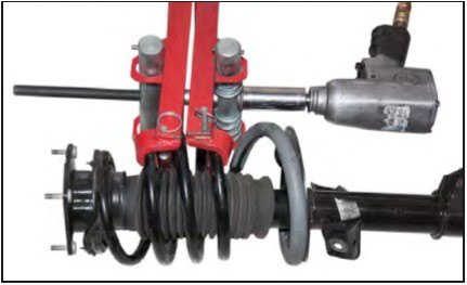
WARNING: Do NOT attempt to disassemble the strut and spring assembly without using a spring compressor. The assembly is under extreme load. Failure to use a compressor can result in serious injury.
12. Compress spring until strut is not under tension.
13. Remove strut shaft nut.
14. Remove upper mount and spring from assembly.
15. Carefully release tension on the spring compressor and remove from spring.
16. Install the new spring in the compressor until it’s short enough to fit back on strut.
NOTE: If installing MM caster camber plates or new struts, refer to manufacturer instructions now.
17. If removed, reinstall bumpstop and dustboot.
NOTE: We highly recommend installing shorter bumpstops (Part#Mm5BSF-1).
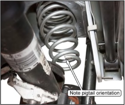
18. When installing the spring onto the strut, make sure spring pigtail is positioned against seat stop and resting in the spring seat pocket.
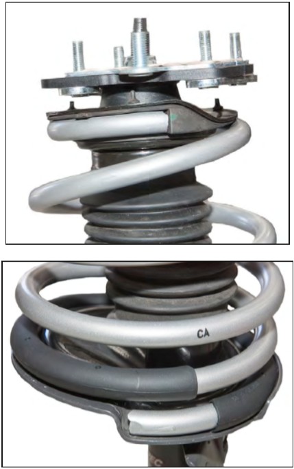
19. Reinstall upper strut mounts or caster/camber plates, ensuring that upper spring completely seats in perch. Torque the strut shaft retaining nut to the OEM torque specification:
GT500 | 80 Nm (59 lb-ft )
2005-2010 | 62 Nm (46 lb-ft)
2011-2014 | 103 Nm (76 lb-ft)
NOTE: If installing or using MM caster/camber plates, refer to your installation instructions.
20. Position strut assembly into car, ensuring upper mount is properly aligned. Hand-tighten the four upper strut mount nuts.
21. Install and tighten spindle-to-strut bolts and nuts. Torque to 225 Nm (166 lb-ft).
22. Tighten and torque OEM upper strut mount nuts to 35 Nm (26 lb-ft).
NOTE: If using caster/camber plates, refer to manufacturer instructions for torque specifications.
23. Re-install brake line bracket and ABS sensor wire. If equipped, connect front strut electrical connector.
24. Repeat Steps 4-23 on other side of car.
25. Install swaybar-to-strut mounts. Torque OEM hardware to 115 Nm (85 lb-ft).
26. Reinstall wheels and safely lower vehicle to the ground. Torque lug nuts to manufacturer’s specifications.
Rear
27. Block front wheels and jack up rear of car.
WARNING: Vehicle must be supported under rocker panel pinch welds (as specified in Ford service manual) to avoid damaging chassis. Do not lift by K-member.
28. Remove swaybar links near lower shock mounts to allow access to shock bolts. Loosen chassis mount hardware, but do not remove it, so the swaybar can swing out of the way.
NOTE: Work on one side of the car at a time.
29. Support the passenger side of the axle housing using a floor jack. Place the floor jack just inboard of the control arm mounting bracket, onto the axle housing.
30. Remove brake hose bracket bolt.
31. Remove lower shock bolt and nut.
32. Slowly lower rear axle until spring becomes loose.
NOTE: Don’t bend, kink, or stretch brake lines when lowering the axle.
33. Remove rear spring.
34. Ensure upper and lower spring isolators are in their proper positions. Install new spring with lower spring pigtail wrapping around the rear of the lower perch.
35. If installing aftermarket shocks or the Mm5BSR-2 rear bumpstops, refer to manufacturer’s instructions and do so now.
36. Jack up rear axle until you’re able to reinstall lower shock bolt.
37. Install brake hose bracket bolt. Torque to 14 Nm (10 lb-ft).
38. Repeat Steps 29-37 on the driver side.
WARNING for customers using stock rubber rear lower control arm bushings:
The rear lower control arm pivot bolts must be completely loosend and then retorqued with the car at ride height. If the car is placed on ramps for ease of access, be sure that all four wheels are up on ramps of equal height. The best method is to have the car on a drive-on lift such as those found at a muffler shop. Failure to loosen and the retorque the bolts with the car at ride height will add undesirable pre-load to the rubber bushings. This will change the wheel rate of the suspension, increase ride harshness, and cause the rubber bushings to wear out prematurely. The OEM bolt torque is 175 Nm (129 lb-ft).
39. Torque OEM lower shock mount bolts to 115 Nm (85 lb-ft).
40. Install stabilizer bar, torque OEM hardware to 115 Nm (85 lb-ft).
41. Reinstall wheels and safely lower vehicle to the ground. Torque lug nuts to manufacturer’s specifications.
