 FREE 1 to 3-Day Delivery on Orders $149+ Details
How to Install MBRP Long Tube Header and Catted H-Pipe Kit - 1-7/8 in x 3 in. on your Mustang
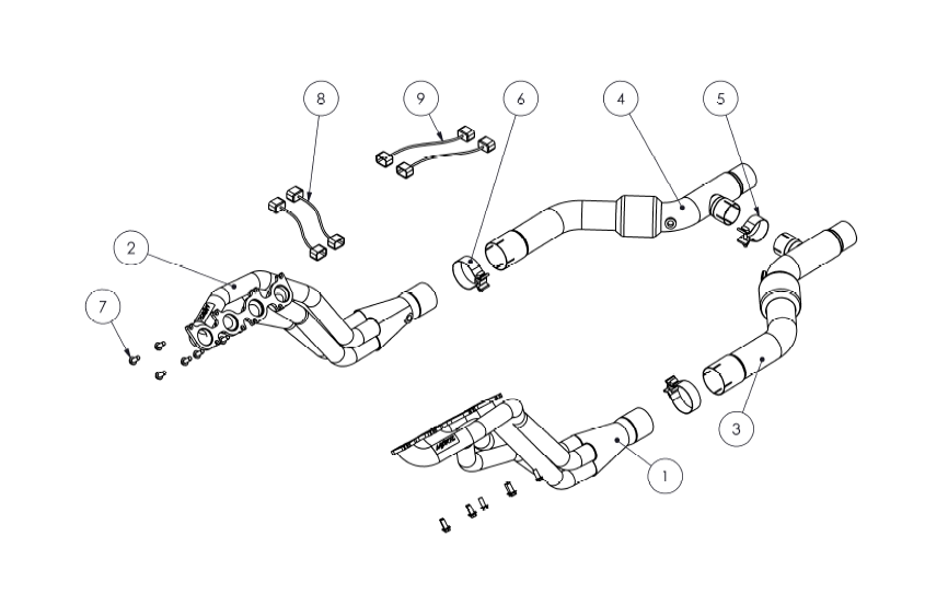
Note: This is an advanced level installation that should be performed only by experienced personnel.
The hardware supplied in this kit is designed to work with cars produced mid-year 2011 and later. Early 2011 cars use M10x1.5x25mm hardware. Please check to ensure the supplied hardware threads into the cylinder head. Contact MBRP for the early build hardware kit.
This kit is designed to work with MBRP S7258 Street or S7264 Race Cat Back exhaust system or OEM.
Removal of Stock System:
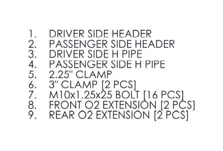
1. Disconnect and remove the Battery, Battery Box and Strut Tower Brace. Refer to Figure 1.
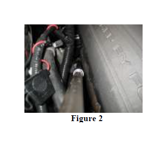
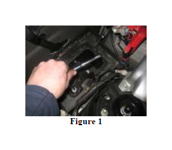
2. Remove the upper nut on the Passenger Side Manifold Flange to the catalytic converter connection. Remove the driver and passenger side Engine Mount Nuts. Refer to Figure 2.
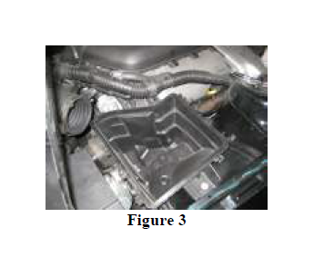
3. Remove the Airbox/Filter assembly. Refer to Figure 3.
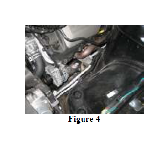
4. Remove as many of the M10 Flange Nuts holding the Manifolds to the Cylinder Heads on both the driver and passenger side as possible from the topside.
Refer to Figure 4.
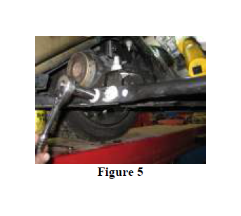
5. Remove the Lower Chassis Brace. Refer to Figure 5.
6. Disconnect the cat back exhaust at the butt joint band clamps located at the end of the h pipe. Remove the cat back exhaust at this time if it is being replaced.
7. From underneath the car, remove the remaining nuts holding the Catalytic Converters on the Exhaust Manifolds and remove the converters.
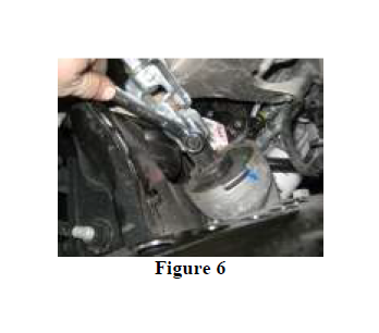
8. Remove the Pinch Bolt from the Steering Shaft and lift the shaft assembly off the Steering Rack. Swing the shaft out of the way.
Refer to Figure 6.
9. Disconnect both front O2 Sensor leads from the vehicle wiring harness.
10. Disconnect the wiring and remove the Starter Motor.
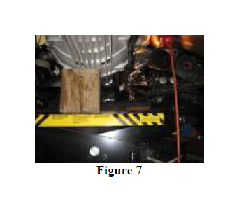
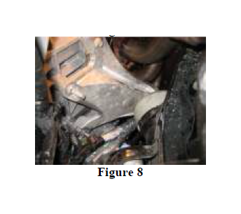
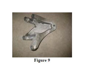
11. Use a block of wood under the Transmission Bell housing and CAREFULLY lift the engine up off the Rubber Engine Mounts just enough to be able to remove the Aluminum Engine Mounts from the Engine Block on the driver and passenger side.
Refer to Figures 7, 8 and 9.
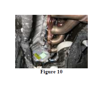
12. Remove the remaining M10 Flange Nuts securing the Exhaust Manifolds to
the Cylinder Heads from below.
Refer to Figure 10.
13. Remove the Exhaust Manifolds and the remaining manifold studs from the Cylinder Heads.
Note: engine must be raised in order to remove the Exhaust Manifolds.
Reference the chart at the bottom of this page for assembly torque specs.
1. Install the OEM Manifold Gaskets onto the Cylinder Head with 4 of the supplied M10 Bolts in the BOTTOM ROW ONLY on both sides.
2. Install the Front O2 Sensor Extensions to the wiring harness.
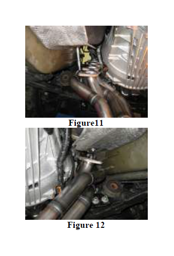
3. Install the MBRP Headers into position and lower them down onto the bolts previously installed in the Cylinder Heads. The header flange is slotted to allow this. Be careful not to damage the Gaskets while installing the headers.
Refer to Figures 11 and 12.
4. Install the remaining M10 Bolts and tighten to 30 lb-ft. A 13mm ratchet wrench will be extremely helpful with this step.
5. Reinstall the Aluminum Engine Mounts and torque to specification. Lower the engine down onto the mounts, reinstall the nuts and torque to specification.
6. Remove the OEM O2 Sensors from the Manifolds and transfer them to the MBRP headers. Connect the O2 Sensors to the Front O2 Extensions. Use wire ties to secure the wiring away from the exhaust.
7. Reinstall the Steering Shaft, Starter, and Lower Chassis Brace. Torque to the specifications shown below.
8. Install a 3” Clamp on each header outlet then install the Driver Side H pipe.
9. Install a 2.25” Clamp on the crossover stub of the Driver Side H Pipe [the driver side has the expanded crossover stub] then install the Passenger Side H Pipe ensuring the crossover stubs align and seat properly.
10. Transfer the rear O2 Sensors to the H Pipes and connect using the supplied Rear O2 Extensions. Use wire ties to secure the wiring away from the exhaust.
11. Install the cat back exhaust, align and tighten all clamps.
12. Reinstall the Air Intake, Airbox Assembly, Battery, Battery Box, and the Strut Tower Brace.
Torque Specifications.
| Aluminum Engine Mount to Block | 41 lb-ft |
| Engine Mount Nut | 46 lb-ft |
| Steering Shaft Pinch Bolt | 35 lb-ft |
| Lower Chassis Brace | 48 lb-ft |
Congratulations! You are ready to begin experiencing the improved power, sound and driving excitement of your MBRP Inc. performance headers. We know you will enjoy your purchase.
