 FREE 1 to 3-Day Delivery on Orders $149+ Details
How to Install McLeod Adjustable Hydraulic Throwout Bearing/Slave Cylinder on your Mustang

Shop Parts in this Guide
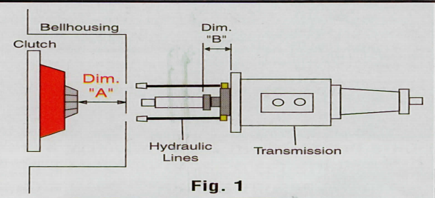
To Determine "Dimension A": With the bell housing, flywheel, disc and pressure plate bolted to he engine, measure the distance from the rear surface of the bell housing tb the top of the release fingers on the pressure plate. If this dimension measures less than 3" you should use a "Bolt-On" style hydraulic throw out bearing assembly. If this dimension measures greater than 3" you should use a Slip-On style hydraulic throw out bearing assembly.
Note: T-56 transmissions have a recessed front intermediate plate. Place a straight edge across the face of the throw out bearing surface and measure to the front face of the front intermediate plate. The bearing assembly on the T-56 is nested inside the front intermediate plate. This "B" dimension must be determined to be certain you have the correct style bearing assembly. (Step 2).
Installation Instructions
Before installing the hydraulic Throw Out Bearing Assembly let's take a look at your master cylinder and pedal assembly combination. Key parts to the system:
1) Master cylinder bore size (3 / 4" recommended). Bore Diameter found on side of most aftermarket master cylinders.
2) Clutch pedal travel.
3) Master cylinder "Push Rod" stroke should be l"minimum.
4) 6:1 Pedal ratio. See http://www.mcleodracing.com/info/?id=5262 for more info.
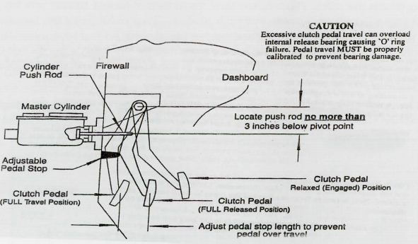
The master cylinder push rod needs a minimum of 1" of stroke if using a ¾" bore master cylinder. Less travel is required with a larger diameter bore, although pedal effort will increase. More travel is required with ,a smaller diameter bore, with decrease in pedal effort. If a larger than ¾" bore is required for your application, you can ease pedal effort by mounting the master cylinder and push rod higher up the pedal toward the pivot point. This will increase the amount of leverage you have with the pedal, thus an easier push. You will lose some push rod travel by doing this however with the larger bore master cylinder you are dispensing more fluid per stroke to compensate for the loss of pedal travel.
A 6 to 1 ratio is recommended with a¾" bore master cylinder. Example .. .If the center of the pedal pad is 12" from the pivot point, the push rod connecting point should be 2" below the pivot point. Quick math: Pedal pad is 12" below pivot point, divided by 6 (desired ratio) = 2". Push rod should be attached to the pedal assembly 2" from the pivot point.
An optional pedal stop may be attached to the pedal or the firewall. A bracket with a bolt and a jam nut work nicely so that the stop is adjustable for more or less travel.
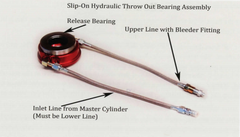
Inspect the bearing assembly and note the AN -4 lines, inlet fitting, swivel fittings, bleeder fitting, release bearing and adjusting screw at rear of assembly. The adjusting screw includes two 0-rings on the ID that will fit tightly onto the transmission input shaft collar. Figure A & B.
Prior to installing the bearing assembly it is strongly recommended you fabricate a protective cover for the AN -4 lines where these lines exit the bell housing. The protective cover can be rubber hose, such as heater hose or similar material. This hose should be about 2" in length for each AN -4 line. Slice the rubber hose lengthwise and slip it over the AN -4 lines and secure with zip ties or safety wire. This will prevent the AN -4 lines from chafing on the bell housing and prematurely failing.
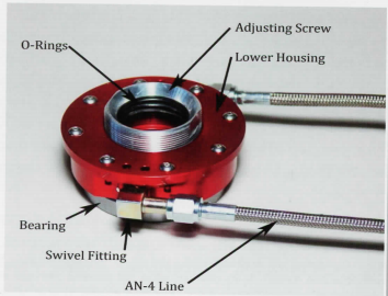
Step 1) Screw the 'Adjusting Screw' all the way into the bearing assembly. Slip the bearing assembly onto the input shaft collar on the transmission. Be sure the tapered side of the adjusting screw goes on the transmission collar to seat against the base of the collar. This should be a tight fit, if necessary to ease installation lube the arings with a light coat of Dot 3 brake fluid or o-ring assembly lubricant. Do not use grease or oil!! Be sure the AN -4 lines are forward for ease of assembly.
Step 2) Take the measurement notes as 'Dimension A'. Note that number here _______
Now measure from the front of the transmission to the front face of the release bearing, this is Dimension "B".
See figure 1. Note that number here _____
Subtract dimension "B" from dimension "A". Note that number here ______ . This will be the clearance for the bearing to self adjust. The total allowable clearance is .100" to .150" maximum. If the bearing assembly is too short, screw the bearing assembly out until the proper clearance is achieved. One complete turn will provide .060" bearing movement forward. Always have the AN -4 line with the bleeder valve at the top when the bearing is properly adjusted. If the desired clearance can only be reached with the bleeder line at the bottom it is OK to swap the lines on the swivel fittings. Remember the line with the bleeder valve must be at the top position!
If 'Dimension B' is too long you can return the slip on bearing assembly to McLeod Racing for a Bolt-On style which can be made shorter than the Slip-On style. This is why the dimension check prior to installation is critical.
STEP 3) The braided steel AN -4 lines on the hydraulic bearing are designed to swivel. Before installing the transmission, swivel both lines forward parallel with the input shaft. See Figure 1. Tie a heavy string around both lines, making the string long enough to feed the string through the opening in the bell housing where the lines will feed through (typically the fork hole) before the transmission is fully engaged into the bell housing. As the transmission is installed into the bell housing the string can be pulled simultaneously, thus swiveling and guiding the AN -4 lines out through the bell housing hole. These lines must not contact the spinning clutch or flywheel when the engine is running. Be sure the protective hose on the lines are in the proper position to protect the AN -4 lines from chafing on the bell housing.
Step 4) After securing the transmission and driveline; connect a line (not included with the bearing assembly) from the master cylinder to the input line (bottom line) of the hydraulic bearing. This bearing assembly is supplied with an AN -4 fitting screwed into the line. Fill the master cylinder with DOT 3 or DOT 4 brake fluid. DO NOT USE SILICONE FLUID or DOT 5 FLUID!! Use of silicone fluid will damage the o-rings resulting in leaks and or damage to the assembly. After the master cylinder is filled, bleed the bearing assembly. Example: Pump the pedal 3 to 4 times, with the bleeder valve open and the end of the opening submerged in a cup partially filled with brake fluid. This will release fluid and air trapped in the system. Continue the bleeding process until all of the air is removed from the system. Now reach into the cup and tighten the bleeder fitting. Set the cup aside and then be sure to tighten the bleeder valve. Once the bleeding is complete refill the master cylinder, just don't fill it all the way to the top. The fluid level should be ½" to ¾" from the top. This will allow room for the brake fluid in the reservoir when the bearing self adjusts. Unlike brakes, the fluid level will rise in the reservoir, as the clutch wears, not lower.

