FREE 1 to 3-Day Delivery on Orders $149+ Details
How to Install a Maximum Motorsports IRS Rear Lower Control Arm Delrin Bushing Kit your 1999-2004 Co

Shop Parts in this Guide
Read all instructions before beginning work.Following instructions in the proper sequence will ensure the best and easiest installation.
Thank you for purchasing the Maximum Motorsports IRS Delrin Lower Control Arm Bushing Kit. This kit will improve handling and reduce wheel hop by eliminating the deflection allowed by the stock rubber lower control arm bushings. The Delrin bushings precisely locate the lower control arms. This maintains rear wheel alignment in a manner that is impossible with the large, compliant stock rubber bushings. While providing adequate suspension control, and noise and vibration reduction, rubber bushings cannot accurately position the control arms well enough to achieve maximum performance from the suspension. Wheel hop is caused by the undamped compression of the rubber bushings in the rear suspension. That undamped movement is further increased by repeated loss of traction. Wheel hop can occur under acceleration or braking. Eliminating the extremely soft stock bushings that compress easily and spring back, causing the tires to continually lose and regain traction, will reduce wheel hop.
There are many features that set our bushing kit apart from the others.
• Stainless steel shims are used to custom fit each bushing and arm combination to the sub-frame, unlike any other kit available. There are very large production tolerances in the fore and aft position of the control arm mounting tabs. The distance between the forward and rearmost tabs can vary by over 1/4"! This works fine for the pliable factory rubber bushings, but not when trying to improve performance by using precisionmachined bushings. This custom fitting process ensures that the control arm cannot shift forward or rearward because of the factory production tolerances. No other bushing kit on the market can accommodate these tolerances, as the MM kit does.
• The shims are installed under the shoulder of the bushing to simplify installation of the assembly into the sub-frame, and retain them in the proper position.
• The Delrin bushing shoulders are chamfered to ease installation, and reduce the slidingfriction contact area with the sub-frame tabs.
• Tooling! We include a set of press tools to remove the stock rubber bushings and shells. There is no need to spend hours at the difficult task of drilling out bushings and cutting up bushing shells. With the MM bushing press tools, all four control arm bushings can be easily removed in a matter of minutes.
• Double-shouldered front and rear bushings are used to evenly spread acceleration and braking loads into the sub-frame. Thrust loads, created by braking and acceleration forces, load the control arms along the pivot axis of the bushings. These loads are taken up by the bushing shoulders and passed into the control arm mounting tabs. The MM kit has a shoulder on both sides of each bushing. This lets both bushings on each arm transmit these thrust loads into the subframe. Single-sided bushing kits concentrate the thrust loads into one or the other bushing, increasing the stress on the control arms and sub-frame.
• The crush sleeves that support the Delrin bushings, are made of thick-walled aluminum, rather than steel, to reduce weight, and are hard anodized to reduce slidingfriction wear.
•Tab-straightening tools are included with the MM kit to assist in flattening the sub-frame tabs before installing the new Delrin bushings. The mounting tabs are distorted on the assembly line when the control arms are originally installed. This is a critical step that ensures that the control arms pivot freely, without binding.
Besides normal hand tools, this installation may require the following items:
Flat file or grinder
Round file or de-burring tool
Small chisel and hammer
Small diameter cut-off wheel
Electric drill motor or die-grinder
Internal-mounted coil spring compressor
Anti-seize compound
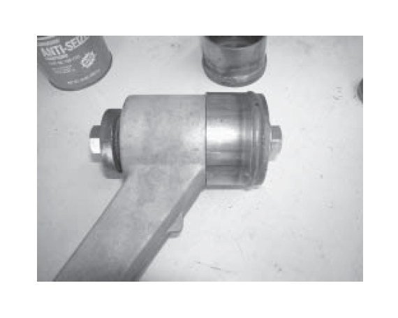
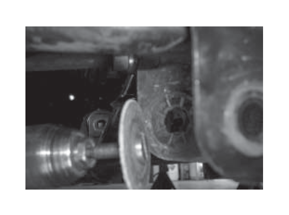
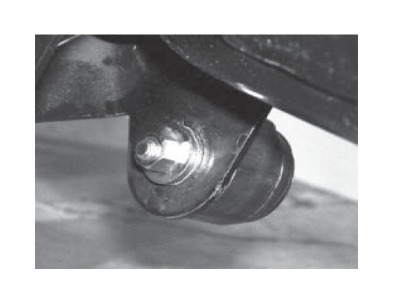
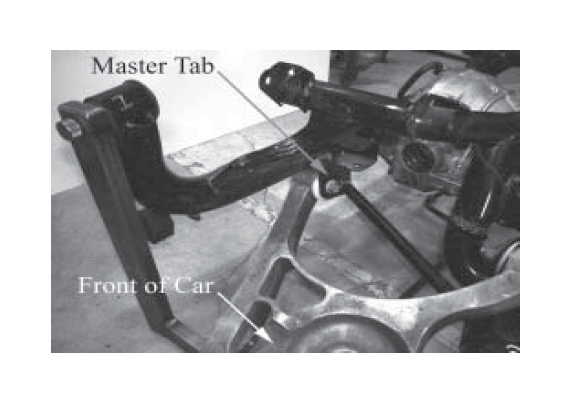
Remove Lower Control Arms
1. Jack up the rear end of the car and place it safely on jack stands. To keep jack stands out of the work area, place them under the vehicle subframe, forward of the IRS.
2. Remove the rear wheels.
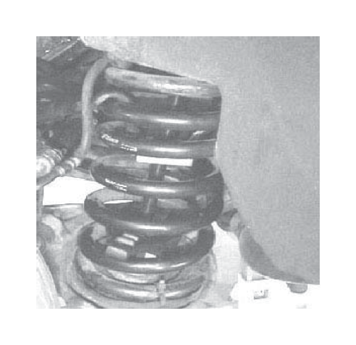
3. After marking the orientation of the end of the rear springs and isolators, use an internalmounted coil spring compressor and remove each rear coil spring. Most auto parts and equipment rental stores rent these types of spring compressors. Be very careful. Springs store a large amount of energy, and serious injury may result if the spring comes loose and goes flying.
4. Disconnect the shocks from the control arm end.
5. Remove the bolt holding the lower control arm to the spindle.
6. Remove the bolt holding the parking brake cable to the control arm.
7. Remove the swaybar link where it connects to the lower control arm.
8. Remove the lower control arm pivot bolts.
9. Remove the lower control arms from the subframe.
Remove Control Arm Bushings
10. Begin by applying a liberal amount of anti-seize compound to the entire threaded portion of the supplied 5/8” fine thread bolt and nut.
11. Place two 5/8” washers under the head of the bolt and insert through the large diameter removal cup.
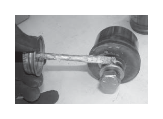
12. Apply anti-seize between the washers, the head of the bolt, and the removal cup.
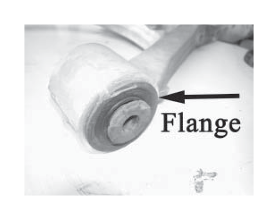
13. Place the large diameter removal cup around the flanged portion of the rearward control arm bushing. The cup should rest completely against the aluminum control arm.
14. Place the large diameter press washer on the opposite side of the control arm bushing.
15. Thread the supplied 5/8” nut on to the bolt.
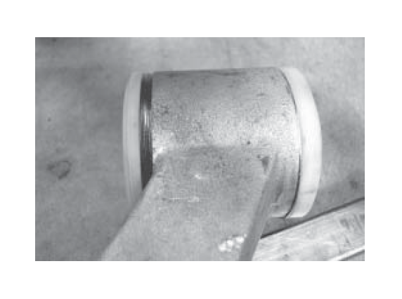
16. Using a wrench and rachet, tighten the bolt until the bushing is pulled free of the control arm. The bushing shell only needs to move about an inch to become free. To avoid damaging the arm, we recommend AGAINST using an impact gun due to the ductility of the aluminum control arm.
17. Repeat for the forward control arm bushing using the smaller diameter removal cup and press washer.
18. Repeat steps 10-17 to remove the bushings from the other control arm.
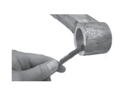
19. Using a small round file or de-burring tool, break the sharp edges on the bushing cup as shown.
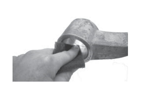
20. Using the supplied Scotch-Brite pad, remove any rust residue from the steel shell and smooth out any rough spots. When finished, wipe the area with a clean rag.
Control Arm Tab Spacer Removal
Note: On most of the IRS units produced, Ford has tack-welded a spacer to the forward mounting tab of the rearward-most control arm mounts. This spacer must be removed to properly install your MM Delrin bushings. If your vehicle does not have this spacer, proceed to the “Straightening of Control Arm Mounting Tabs” section.
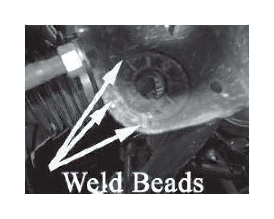
21. Using a small cut-off wheel attached to a drill or die-grinder, grind through the weld beads attaching the spacer to the tab. DO NOT grind deeper than necessary, the surface must be smooth for the MM delrin bushings to function properly.
22. Using a small chisel and hammer, pry the spacer away from the mounting tab.
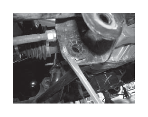
23. Using a file or small grinder, remove any remnants of the weld beads from the tab. The surface must smooth before the MM delrin bushing installation can proceed.
24. Repeat steps 21-23 to remove the spacer located on the other side of the vehicle.
Straightening of Control Arm Mounting Tabs
25. The control arm tabs will be deformed from the control arm mounting bolts being tightened at the factory. Straighten all 8 mounting tabs.
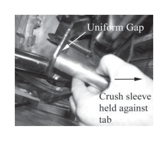
Note: This is a vital step. Proper tab straightening will minimize bind between the bushing shoulder and the mounting tabs. It will also leave a much more uniform gap when installing the bushing shims, leaving less chance for slop along the control arm pivot axis on the completed installation.
26. You will use the crush sleeves to check the tabs. Sleeves should fit easily between the tabs. Don’t force the crush sleeves if the tabs aren’t spread completely. You may need to do some initial tab straightening & spreading with a crescent wrench, or with a hammer & punch.
Note: Use the short crush sleeves to check the front tabs, and the long crush sleeves to check the rear tabs.
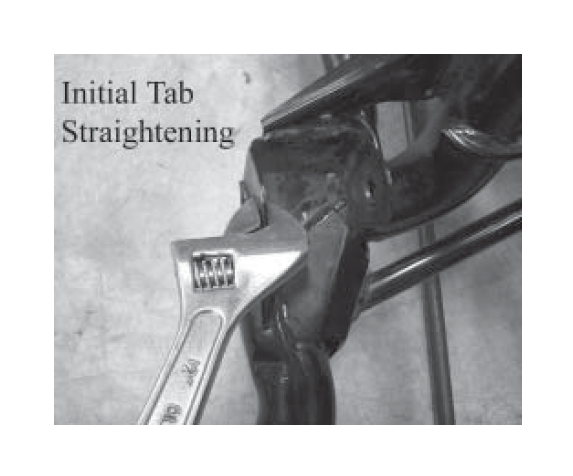
27. Set the cup tool on the outside of the tab. Place the 3/8 flat washer under the bolt head. Run the bolt through and place the thick washer and nut on the inside of the tab. Use anti-seize or oil on the threads and washer surfaces.
28. Tighten the bolt to pull the tab straight. Be careful to not over bend the tab. It may be necessary to move the setup around and repeat the process to flatten the entire mounting surface.
Note: To check tab straightness, set the crush sleeve flush against one tab. There should be a uniform gap from the crush sleeve to the tab at the other end. Continue the process until the tabs are straight.
29. At this point, check the inner surface of each control arm mounting tab for weld spatter from Ford’s production process. It is important that the mounting area of the Delrin be smooth to reduce friction. If any weld spatter is present, use a chisel or flat file to remove it.
Install Bushings
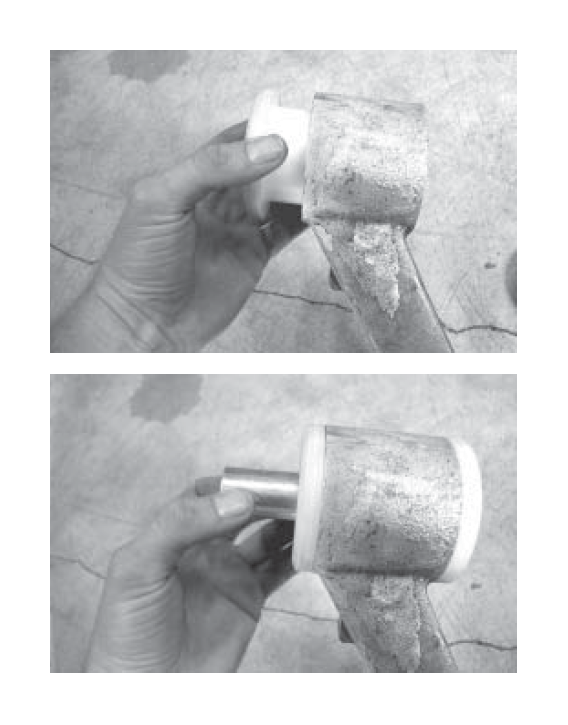
30. Install the bushings and crush sleeves in the control arms. Note the differences in the lengths of the crush sleeves and the diameters and lengths of the Delrin bushings.
The larger OD (Outside Diameter) bushing sets- These sets use the long crush sleeves. These fit into the rear side of the control arm (the side where the shock mounts). Note that each bushing set has a long and a short Delrin bushing, and that each of those bushings has a slightly different diameter.
The smaller OD bushing sets- These sets use the short crush sleeves. These fit into the front side of the control arm (the side with the spring perch). Note that each bushing set has a long and a short Delrin bushing, and that each of those bushings has slightly different diameter.
The diameters of the Delrin bushings in each set are different so they will properly fit the bushing bores in the control arm, as each bore has a machined step in it. Be sure to use the correct diameter and length bushing for each side of the bore.
Do not grease the bushings yet; they will be lubricated during a later step.
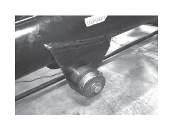
31. Install the arms into the sub-frame. Snug the mounting bolts, but do not fully torque. The arms will be removed again later. Note: You will notice a gap between the bushings and the mounting tabs, especially at the front set of tabs. This is to be expected, and will be taken up with the shims.
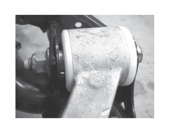
32. Push the arm against the “Master Tab.” This is the tab that has a reinforcement tube welded to it. It is the front-most tab of the rear control arm mount. The arm will be pushed toward the front of the car. No shims are used at the Master Tab.
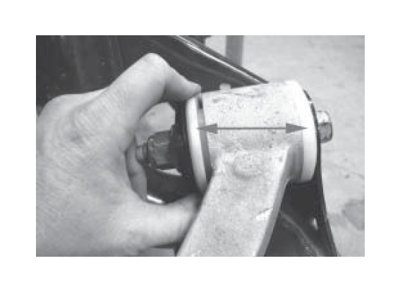
33. On all of the other bushings, open up a gap between the bushing shoulder and the control arm shoulder by pulling the bushings away from the arm, toward the mounting tab surface as shown.
Note: There are four types of shims provided with each kit: Large diameter shims (thick and thin) for the large bushings, and small diameter shims (thick and thin) for the smaller bushings. More are provided for the smaller bushings since they will require thicker shim stacks.
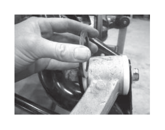
34. Using the shims as feeler gages, determine the proper shim stack at each bushing. Make the stack as thick as possible, while still allowing the stack to slide freely between the bushing shoulder and mounting tab surface. Start by adding thick shims until the stack is too big. Then remove one thick shim and try a thin one. If it is still too big, remove the thin shim.
Note: The front bushing set will require a larger stack than the rear. It is okay if the shim stacks are different side-to-side on the car. It is possible that one end of the front bushing set may not require shims. Record the shim stack (thickness and quantity of shims) for later reference.
35. Remove the arms from the car.
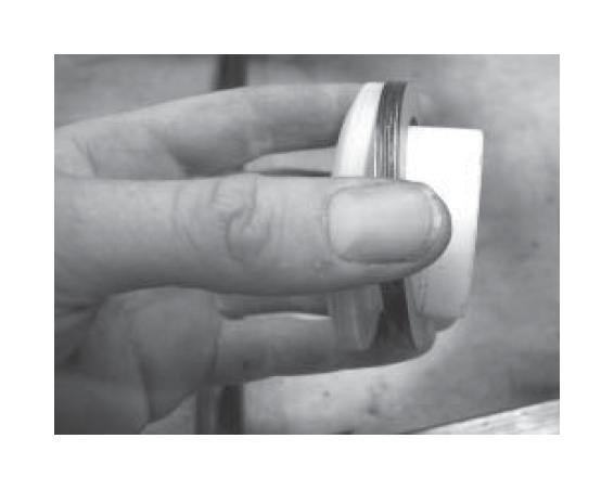
36. Install the correct shim stack recorded during the previous step on each of the bushings by sliding the shims onto the OD of the bushing as shown.
37. Reinstall the bushings, shims, and crush sleeves in the control arms.
38. Reinstall the arms on the car. Snug, but do not fully torque, the pivot bolts.
39. Check for bind in the system. The lower control arm should pivot freely by hand. If it does not, determine where it is binding and take corrective action. It may require additional straightening of the control arm tabs, or removal of shims, or both.
40. Remove the control arms for final assembly.
41. Remove the bushings and crush sleeves. Keep the shims in place on each bushing. Work on one side of the car at a time to avoid mixing up the bushings and shims.
42. With the supplied grease, lubricate the outside of the crush sleeves and the outside diameter of the bushings where they slide into the control arm. Note: The supplied grease is extremely difficult to remove from your skin and clothing. We have supplied a set of latex gloves for your protection during lubrication application.
43. Reinstall the arms and torque the bolts to 184 ftlbs. Recheck the arms to make sure they still pivot freely.
44. Reassemble the other components removed previously. Be sure to orient the springs according to the marks previously made. Tighten all components to factory specifications.
Lower shock bolt: 98 ft-lbs.
Lower control arm to spindle bolt: 85 ft-lbs. Swaybar link nut: 35 ft-lbs. Parking brake cable bracket 5 ft-lbs.
45. Install the wheels and torque the lug nuts to either the wheel manufacturer’s or factory specifications.
46. Take the car off the stands, drive, and enjoy! Recheck and re-torque all components after 1,000 miles.
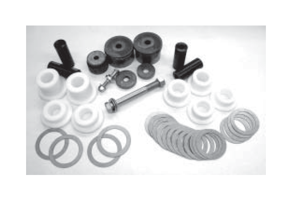
| Qty | Description | |
|---|---|---|
| 2 | Delrin Bushings, ~3” Shoulder, Long | |
| 2 | Delrin Bushings, ~3” Shoulder, Short | |
| 2 | Crush Sleeves, Front | |
| 2 | Delrin Bushings, ~2-3/4” Shoulder, Long | |
| 2 | Delrin Bushings, ~2-3/4” Shoulder, Short | |
| 2 | Crush Sleeves, Rear | |
| 12 | Shims, ~2-3/4” Diameter, Thick||
| 4 | Shims, ~2-3/4” Diameter, Thin | |
| 2 | Shims, ~3” Diameter, Thick||
| 2 | Shims, ~3” Diameter, Thin | |
| 1 | Tab straightening cup | |
| 1 | 3/8-16 x 2-1/2” G8 bolt | |
| 1 | 3/8-16 G8 nut | |
| 1 | 3/8 G8 flat washer | |
| 1 | 3/8 x 1 x 1/4 thick washer | |
| 1 | Large diameter bushing removal cup | |
| 1 | Large diameter bushing press washer||
| 1 | Small diameter bushing removal c | |
| 1 | Small diameter bushing press washer | |
| 1 | 5/8-18 x 5-1/2” G8 bolt | |
| 2 | 5/8 G8 flat washer | |
| 1 | 5/8-18 G8 nut | |
| 1 | Small Scotch-Brite pad||
| 4 | Grease packets | |
| 2 | Latex gloves |