 FREE 1 to 3-Day Delivery on Orders $149+ Details
How to Install Daytime Running Lights in your 2010-2012 Mustang
Installation
- Heat Gun
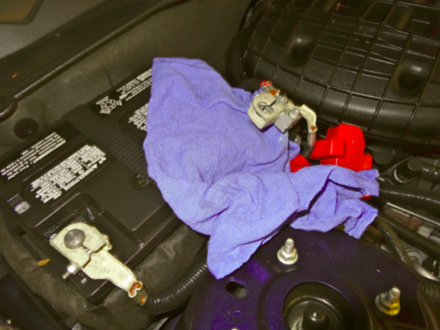
1. It is recommended that the positive terminal be removed from the battery prior to any electrical installation. A good tip to follow once the terminal is loosened and removed, is to place a workshop rag over the battery. Battery cables have a tendency to “creep” back to their original location and this will prevent any surprises while you are under the dash.
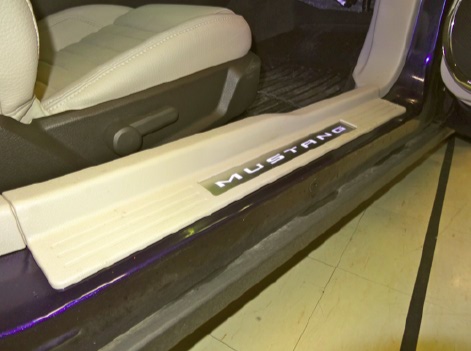
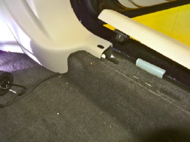
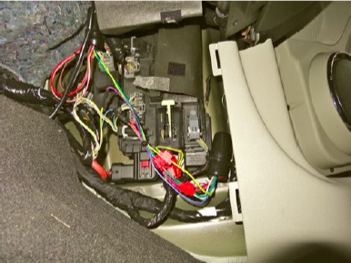
2. Remove the fuse panel cover at the back of the passenger kick panel. Four clips on the carpet side and double-sided tape on the exterior body side hold the sill plate in place and there is no need to remove the entire sill plate. The tape is very adhesive and there is a tendency to bend the metal Mustang nameplate if you try to remove the entire sill. Pull up on the carpet side at the front of the sill along with the front adhesive tape. Your goal here is to allow the passenger kick plate to be removed from under the sill plate without pulling the entire sill plate off. Next pull back on the kick plate, as there are a number of clips holding it on.
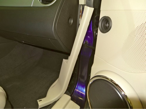
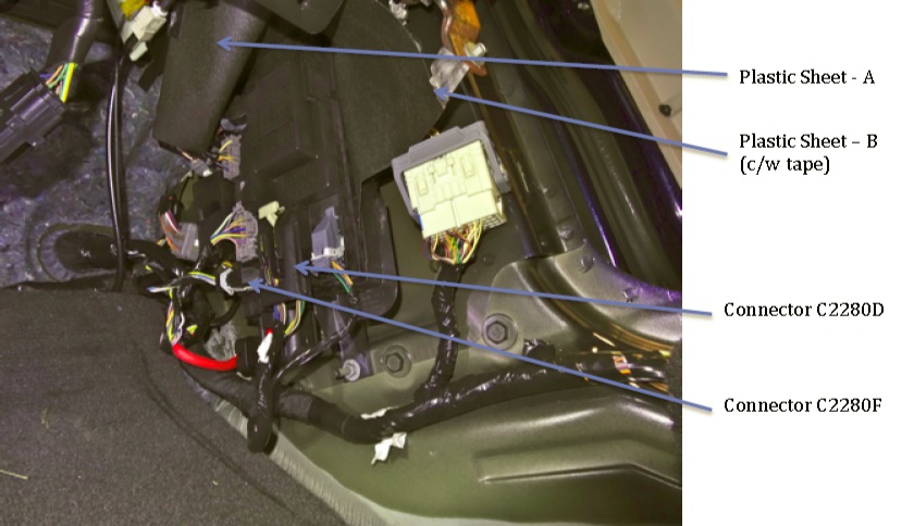
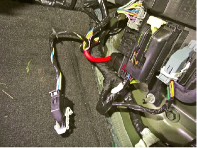
3. Now that the Smart Junction Box area is exposed lift up on the thin black plastic sheet (A) covering the connectors and fuse box. The second black plastic sheet (B) is held in place by white tape. Peel this off the junction box and keep it on the plastic sheet for later reassembly.
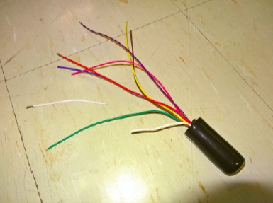
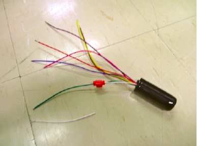
4. If you elect to use the synchronizing wire as described in the instructions you will need to prepare the module, which is easier done outside of the car. Cut the white wire in half and use the “quick splice” connector to attach it to the green wire.
5. Snap and slide the white clip on top of connector C2280F to the left to release the connector from the junction box. Carefully cut the black “wrap tape” from the wire harness and locate the “blue/green” and “yellow/violet” wires. Cut the two wires half way up the wiring harness and strip the ends.
Your Mustang's daytime runing light kit is supplied with white Marrett or Wire-nut joiners, which at this point you can use to join the wires. If you have access to a soldering iron and heat shrink tubing this would be the best method to connect the wires in all electrical projects.
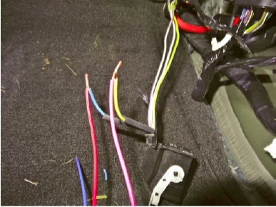
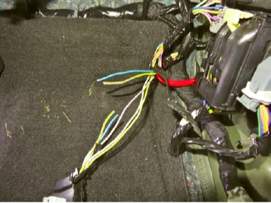
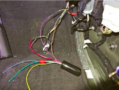
6. Slide a 1.5” length of 3/16” heat tubing over the red wire from the DRL module. Twist the blue/green wire from the connector to the red wire. Solder and then fold over one of the wires. Slide the heat shrink tubing over the solder joint and warm with a heat gun.
7. Slide a 1.5” length of 3/16” heat tubing over the pink wire from the DRL module. Twist the yellow/violet wire from the connector to the red wire. Solder and then fold over one of the wires. Slide the heat shrink tubing over the solder joint and warm with a heat gun.
8. Slide a 1.5” length of 3/16” heat tubing over the violet wire from the DRL module. Twist the yellow/violet wire from the wiring harness to the red wire. Solder and then fold over one of the wires. Slide the heat shrink tubing over the solder joint and warm with a heat gun.
9. Slide a 1.5” length of 3/16” heat tubing over the brown wire from the DRL module. Twist the blue/green wire from the wiring harness to the brown wire. Solder and then fold over one of the wires. Slide the heat shrink tubing over the solder joint and warm with a heat gun.
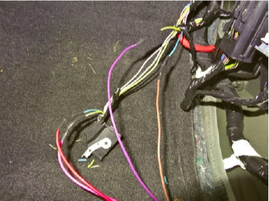
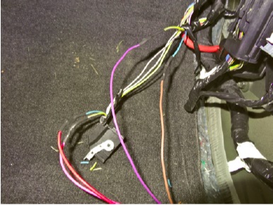
10. Pull down on the white tab to remove connector C2280D from the junction box. Carefully cut the black “wrap tape” from the wire harness and locate the “yellow/gray”, the “ violet/white” and the “black/white” wires.
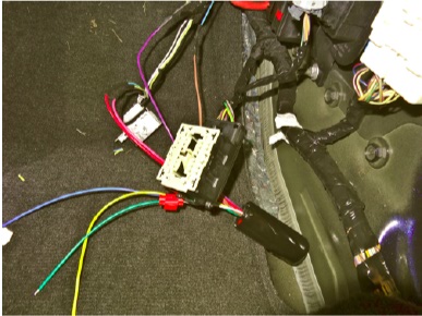
You may wish to insert a small screwdriver into the backside of the connector to unclip the connector cover. This will allow you to separate all the wires and verify the correct wires and pins inside the connector since a few of them look quite similar.
11. Using the “quick splice” connectors supplied, connect the blue wire to the “violet/white” wire of the harness.
12. Using the “quick splice” connectors supplied, connect the yellow wire to the “yellow/gray” wire of the harness.
13. Using the “quick splice” connectors supplied, connect the green wire to the “black/white” wire of the harness.
Use the supplied wire ties to secure the module to a convenient fix point along with using a wire tie to tidy up any loose wires.
• This guide is to be used in conjunction with the instructions provided by the manufacturer and or vendor.
Installation Instructions written by AmericanMuscle customer David Orlando 2.1.13
